1. Introduction
Arc suppression coils have been widely used in power distribution systems in China and Europe [
1,
2]. When a single-phase-to-ground fault (SPG) occurs in the distribution network, the arc suppression device will compensate the fault current and then prevent the fault arc from reigniting [
3,
4]. The effective operation of arc suppression devices relies on the accurate selection of faulty phases. Faulty phase selection failure will lead to an in-crease in the ground fault current and not only cannot achieve the fault arcing but also increases the chance of arc reignition [
5,
6,
7]. Seriously, there may be a large-area short circuit of the system due to intermittent overvoltage.
Traditional faulty phase selection methods directly judge the phase with the lowest phase voltage as the faulty phase when a SPG occurs in a resonant grounded distribution network [
8]. However, in the case of high-resistance ground faults, the phase with the lowest phase voltage is no longer the faulty phase. To solve this problem, another power frequency-based faulty phase selection method is proposed by some scholars. When the system is in the overcompensation state, the phase leading the highest voltage phase is the faulty phase, and when the system is in the under-compensation state, the phase lagging the highest voltage phase is the faulty phase. Since the above methods can only be used for symmetrical systems, Xu [
9] proposed a method to select the faulty phase by constructing a “phase vector”, which used an asymmetric vector to determine the faulty phase, but its calculation process was too complicated. In addition, Meng [
10] proposed a faulty phase identification method based on the zero-sequence voltage variation law, which was easy to implement in a digital processor. In reference [
11], the Clark Modal Transform (CMT) was used to extract the zero-sequence components from the three-phase voltages, combined with the voltage phase angle shift to determine the faulty phase in the 33-kV distribution system. To avoid the complicated selection process, Wang et al. [
12] determined the faulty phase based on the phase voltage variation after the injection of a compensation current at the neutral point in a distribution system with fully compensated arc suppression technology, while Fan et al. [
13] proposed a faulty phase recognition method based on phase-to-ground voltage variations, who analyzed the effects of system asymmetry and fault resistance in ungrounded distribution systems. All of the above methods are based on steady-state signals, where the selection of the faulty phase is achieved by the power frequency-based amplitude and phase characteristics of the voltage and current before and after the fault. However, the application of these methods is susceptible to interference from factors such as fault resistance values, system grounding methods and system asymmetries.
The transient process of the power system contains abundant fault signals, and various criteria using fault transient characteristics have been applied in the field of relay protection of the distribution system, such as faulty line selection, fault diagnosis, fault section location, etc. [
14]. The relay protection method based on a transient quantity is effective, unaffected by the arc suppression coil, and has a higher sensitivity and better reliability [
15]. In reference [
16], the gray-scale image was synthesized from the zero-sequence current signal of the system through continuous wavelet transform (CWT), and then, the neural network was used to adaptively extract the fault features to identify the faulty feeder. Compared with reference [
16], in addition to using the neural network to detect the faulty feeder, Guo et al. [
17] used a feature fusion method, which relieved the dependence of the neural network-based methods on the amount of data. Guo [
18] also used a 1D convolutional neural network (1D-CNN) and waveform concatenation to overcome the difficulty of feature extraction and classifier selection. This method can effectively realize the fault location in the case of high-resistance SPG.
In the field, the transient faulty phase selection methods are interfered with less by the grid structure parameters and fault resistance, which have become a hot research topic in power transmission systems [
19]. In references [
20,
21], the affiliation function was constructed from the angle difference and amplitude difference among the basic fault current sequences through WT, and fuzzy logic was used to realize the fault-type diagnosis. Salim et al. [
22] extracted the characteristic quantities in a specific frequency band from the transient voltage and current information collected and selected the faulty phase by comparing the threshold values of the faulty phase and the sound phase. Hong et al. [
23] proposed an intelligent faulty phase selection method by applying trained deep belief networks (DBNs), which preprocessed the original data to obtain one-dimensional data by min–max standardization and waveform splicing. These faulty phase selections can be effectively realized in the transmission systems. However, they cannot be directly used in a resonant grounded distribution network because of the different sequence impedances, especially the zero-sequence impedance.
Indeed, once a SPG fault occurred on the distribution feeder, there were abundant electromagnetic transient signals because of the energy interactions among the faulty phase and two sound phases. The waveforms of different phase currents may exist as distinguished features. Some papers have used the similarity measurement results of the voltage or current waveforms to achieve a power line protection function [
24,
25,
26,
27]. Our research also showed that there is a significant difference between the waveforms of the phase current mutation of the faulty and sound phases. Therefore, it is a viable method to analyze the waveform similarity to select the faulty phase.
In this paper, a faulty phase selection method based on the transient current similarity measurements is proposed for a power distribution system. After a SPG occurs in the distribution network, there is a difference in the waveform of the transient phase current mutation between the faulty phase and the sound phase. The HD algorithm is able to determine the degree of similarity between the waveforms and can be used in cases of high-resistance ground faults. The optimized HD matrix (MOHD) was first proposed in this paper, and it can adaptively determine the sampling time window. The MOHD is constructed by the transient currents similarity measurement in the divided faulty phase selection units (SUs). The effectiveness of the proposed faulty phase selection method is verified under various kinds of fault conditions in PSCAD/EMTDC and MATLAB. The rest of this article is organized as follows.
Section 2 describes the reasons why the traditional faulty phase selection methods are not feasible when a high-resistance SPG occurs.
Section 3 introduces the basic principles of the proposed faulty phase selection method.
Section 4 presents the flow of the SPG faulty phase selection method based on the HD and the MOHD. In
Section 5, a typical resonant grounded distribution system is modeled based on PSCAD/EMTDC to verify the accuracy of the proposed faulty phase selection methods. In
Section 6, the effectiveness of the proposed method is discussed in different fault resistances, fault inception angles, system topologies and sampling time windows. The conclusions are presented in
Section 7.
2. Analysis of Phase Voltage under High-Resistance Ground Fault
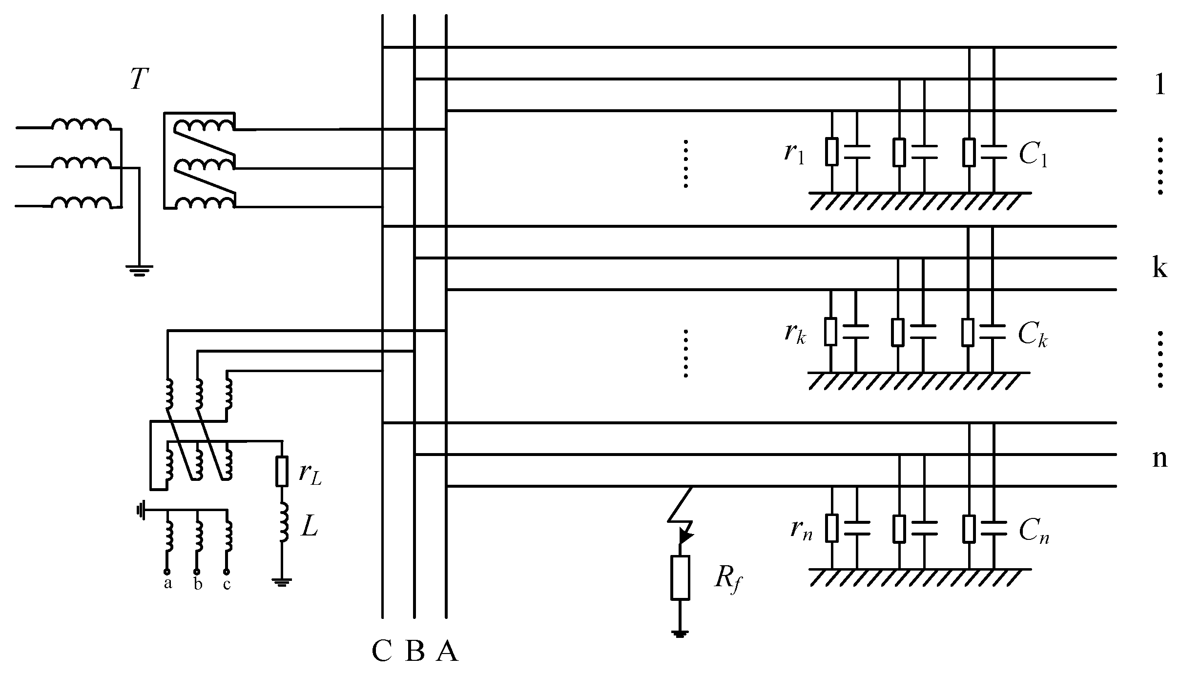
When SPGs occur in the noneffectively grounded distribution system, the phase with the lowest phase voltage is identified as the faulty phase. When the fault resistance is large, the steady-state characteristics of the system are weak, and the use of this method can lead to misclassifications. There is a SPG in the resonant grounded distribution system, as shown in
Figure 1.
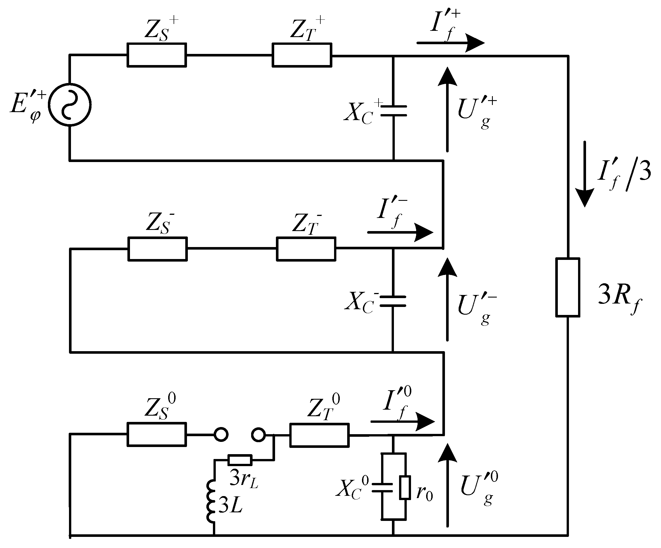
The composite sequence network diagram formed based on the symmetrical component method is shown in
Figure 2.
,
and
, respectively, are the system’s capacitive reactions of the positive-sequence, negative-sequence and zero-sequence.
,
and
, respectively, are equivalent three-sequence voltage sources at the fault point.
,
and
are the three-sequence fault currents at the fault point, respectively.
,
and
, respectively, are the three-sequence equivalent impedances of the distribution system feeders.
,
and
are the positive-sequence, negative-sequence and zero-sequence impedances of the HV/MV transformer, respectively.
is the positive sequence power electromotive force of the distribution system.
The three-sequence fault current at the fault point in
Figure 2 is given by
is the electromotive force of the power supply.
,
and
, respectively, are the three-sequence equivalent impedances of the feeder from the bus to the fault point. In a resonant grounded system, there are
and
, and the Equation (1) becomes
where
There is a large resistance between the distribution network and ground. The zero-sequence impedance of the HV/MV transformer and the zigzag transformer is very small, and the resistance of the arc suppression coil is also very small. Therefore, the
, the
and
are ignored in Equation (3). According to Equations (2) and (3), the zero-sequence voltage
can be obtained as follows:
Therefore, the three-phase voltage
,
and
can be expressed by
A medium voltage distribution system is modeled in PSCAD/EMTDC. The three-phase power supply voltage is 110 kV, connected to a HV/MV transformer with a rated capacity of 50 MVA and a rated ratio of 110/10. Seven feeders are connected to the secondary transformer. The length of all the feeders is 20 km. The arc suppression coil is grounded through the secondary side of the zigzag transformer, and the equivalent inductance value is 0.1078 H. The rated capacity of the distribution transformer is 0.63 MVA. The distribution loads are connected to the end of the feeders with capacity of 0.39 + j0.18 MVA.
The parameters of the feeder are as follows:
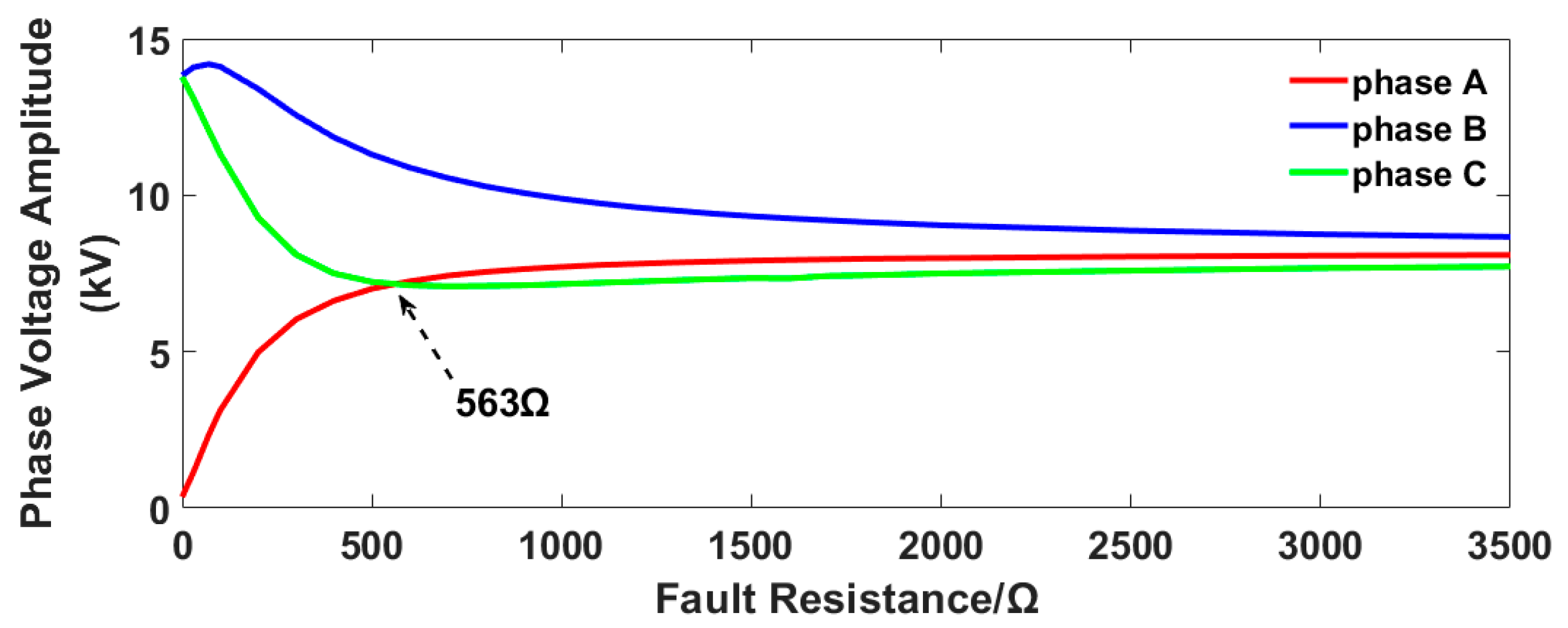
Assuming a SPG occurs in phase A of the distribution system, the relationship between the three-phase voltage amplitude and the fault resistance is shown in
Figure 3.
It can be seen from
Figure 3 that, when a SPG occurs in phase A of the distribution system, with the increase of the fault resistance, the voltage amplitude of phase A will no longer be the lowest. When the fault resistance is greater than a certain threshold, the traditional faulty phase selection method will misjudge phase C as the faulty phase. The proposed faulty phase selection method based on transient current similarity measurements in this paper can avoid the interference of the fault resistance and select the faulty phase exactly.
3. Basic Principle of the Proposed Method
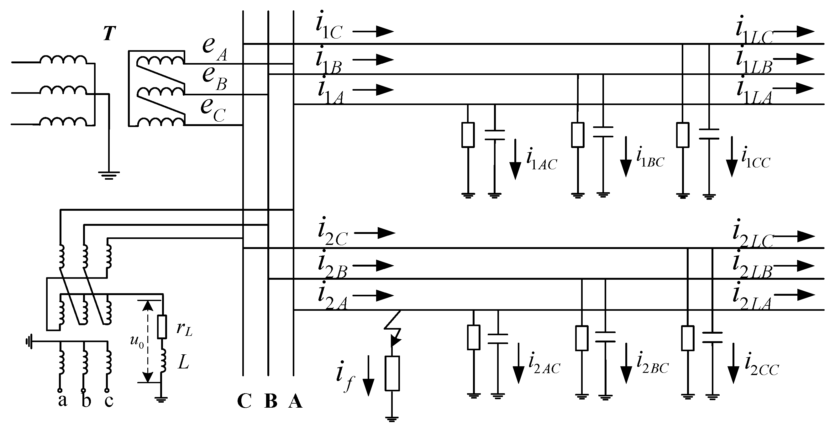
The distribution system currents under a SPG are shown in
Figure 4.
is the phase current near the bus bar on line
k.
is the capacitance current to the ground on line
k.
is the load current of line
k.
is the fault current at the grounding point (
k is the serial number of the feeder;
p can be the A, B or C phase).
When there is no fault in the distribution network, the feeder phase currents are expressed by
is the neutral point voltage before the fault.
is the effective value of the phase voltage. In
Figure 4, the phase currents of the sound feeder and the sound phase of the faulty feeder are expressed by
is the neutral point voltage after the fault.
is the phase current near the bus after the fault. When a SPG occurs in the distribution system, the line voltage of the system remains constant, so the load current
before and after the fault also remains constant, assuming that the source voltages before the fault have sinusoidal variations over time. In
Figure 4, the faulty phase current of fault feeder in the distribution system is expressed by
is the capacitance current to the ground after the fault. is the capacitance current amplitude. is the initial phase angle of the fault voltage. is the angular frequency of the free oscillation component. and are the equivalent time constant. , and are related to the inductance value of the arc suppression coil, the leakage impedance to the ground and the capacitance to the ground.
is made up of the capacitive current to the ground, the load current, the steady-state component of the fault current and the transient component of the fault current. The steady-state component of the fault current is expressed by , which is the difference between the magnitude of the steady-state capacitive current and the steady-state inductive current. The transient component of the fault current is expressed by , which is the sum of the transient free oscillatory component of the capacitive current and the transient DC component of the inductive current.
By subtracting Equation (8) from Equation (10), the phase current mutation of phase A of feeder 2 where a SPG occurs can be expressed by
By subtracting Equation (8) from Equation (9), the phase current mutation of the sound feeder and the sound phase of the faulty feeder can be expressed by
In a distribution system with
k feeders, when a SPG occurs in phase A, the phase current mutation in phase A on the low-voltage side of the HV/MV transformer can be expressed by
The phase current mutation of the sound feeder and the sound phase of the faulty feeder on the low-voltage side of the HV/MV transformer can be expressed by
According to Equations (13) and (14), the conclusions are as follows:
When a SPG occurs in the distribution system, for the sound phase current on the low-voltage side of the HV/MV transformer, the phase current mutation is the sum of the phase-to-ground capacitance current changes. For the faulty phase current on the low voltage side of the HV/MV transformer, the phase current mutation is the sum of the phase-to-ground capacitance current changes and the power–frequency steady-state current components and the power–frequency transient current components at the fault point.
When a SPG occurs in the distribution system, one faulty phase current and two sound-phase currents are collected on the low voltage side of the HV/MV transformer. The similarity between the phase current mutation waveforms of the two sound phases is high. There is a significant difference between the phase current mutations of the faulty phase and the sound phase, and the similarity between the phase current mutation waveforms of the faulty and sound phases is low.
4. Faulty Phase Selection Method Based on HD and MOHD
At present, there are two main image similarity algorithms. One is to judge, based on the characteristic points between the images, the typical Hausdorff distance algorithm [
25,
26]; the other is to judge, based on the gray information between the images, a typical gray correlation analysis [
27]. In this section, the HD was used to calculate the similarities among the transient three-phase current mutations when the SPGs occurred. Then, the faulty phase selection criterions suitable for the distribution system were derived, and the SPG faulty phase selection method based on HD was formed.
4.1. HD-Based Faulty Phase Selection Process
The calculation object of the Hausdorff distance algorithm is the discrete dataset of the two images to be compared. Its calculation results are the characteristics’ distances between the two datasets, which can reflect the similarity between the two datasets and the similarity of the two images. The proposed faulty phase selection method based on HD includes the following four parts.
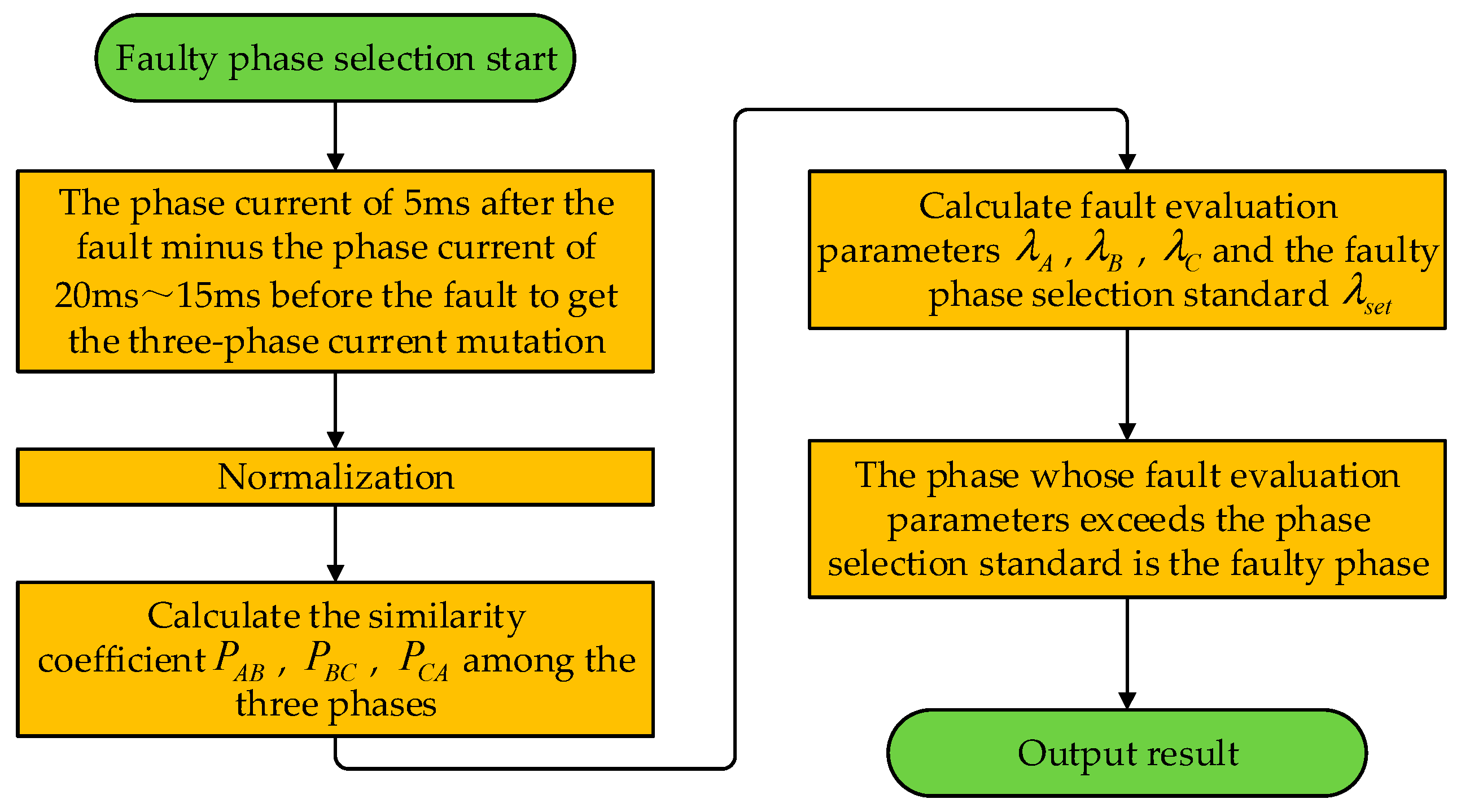
4.1.1. Data Sampling and Normalization
The proposed faulty phase selection method performs similarity calculations and faulty phase selection based on the phase current mutation of a one-quarter cycle.
Using 20 kHz as the sampling frequency, we collected the three-phase current of the low-voltage side of the HV/MV transformer 20~15 ms before the fault and 5 ms after the fault, totaling 600 data. The phase current sequences after the fault minus the ones before the fault achieve the phase current mutation data of the three-phase current, with 100 data per phase. The sampling data sequence of the phase A current mutation is defined as ; the sampling data sequence of the phase B current mutation is defined as . The sampling data sequence of the phase C current mutation is defined as .
Normalizing the sampling data of the current mutation obtains the three-phase current mutation data sequence
,
and
, and the following relations are satisfied:
4.1.2. Obtaining the Similarity Coefficient among the Three Phases
The similarity coefficient of the A–B phase current mutation is , the similarity coefficient of the B–C phase current mutation is and the similarity coefficient of the C–A phase current mutation is .
The calculation process of the similarity coefficient of the A–B phase current mutation is as follows:
• First step
We calculated the absolute value of the difference between the first data
in
and all the data in
and selected the minimum value
among the above absolute values, which is given by
• Second step
According to the similar method, we calculated to in turn to form sequence and selected the maximum value in as the one-way distance from A to B.
• Third step
We used the same method to calculate the one-way distance
from B to A and selected the larger of
and
as the similarity coefficient
of the A–B phase current mutation, which is expressed by
The calculation process of the similarity coefficient of the A–B phase current mutation is completed. The similarity coefficient of the B–C phase current mutation and the similarity coefficient of the C–A phase current mutation can be calculated by the same method.
4.1.3. Obtaining Faulty Phase Selection Parameters
We defined the average similarity of the current mutation sequence of phase A as
, defined the average similarity of the current mutation sequence of phase B as
and defined the average similarity of the current mutation sequence of phase C as
. They can be expressed by
We defined the phase A fault evaluation parameter as
, defined the phase B fault evaluation parameter as
and defined the phase C fault evaluation parameter as
. They can be expressed by
We set the faulty phase selection standard
and the sensitivity factor
(
) to indicate the practicality of the proposed method.
is expressed by
4.1.4. Faulty Phase Selection Process
When a SPG occurs in a resonant grounded distribution system, the process of the proposed faulty phase selection method based on HD in this paper is as follows.
Firstly, we performed data sampling and normalization. Secondly, we calculated the phase-to-phase similarity coefficient. Then, we calculated the faulty phase selection parameters. Finally, we compared the A, B and C phase faulty evaluation parameters and the faulty phase selection standard, respectively.
If
, it is judged that there is a SPG occurring in phase A; if
, it is judged that there is a SPG occurring in phase B and if
, it is judged that there is a SPG occurring in phase C. The faulty phase selection flowchart is shown in
Figure 5.
4.2. MOHD-Based Faulty Phase Selection Process
In the field, there is a short transient process when a SPG occurs in the distribution system. The duration of the transients also varies for different scales of the system. The moment of fault occurrence is determined by detecting a sudden rise in zero-sequence voltage at the substation. The distribution system operates in a harsh environment, and the signals are easily disturbed by a variety of factors. It may happen that the collection terminal online is not sampled for a very short time after the zero-sequence voltage fluctuates, resulting in the loss of transient fault data. The HD-based faulty phase selection method proposed in
Section 4.1 uses a fixed 5-ms time window. In the field, the faulty phase may be incorrectly selected.
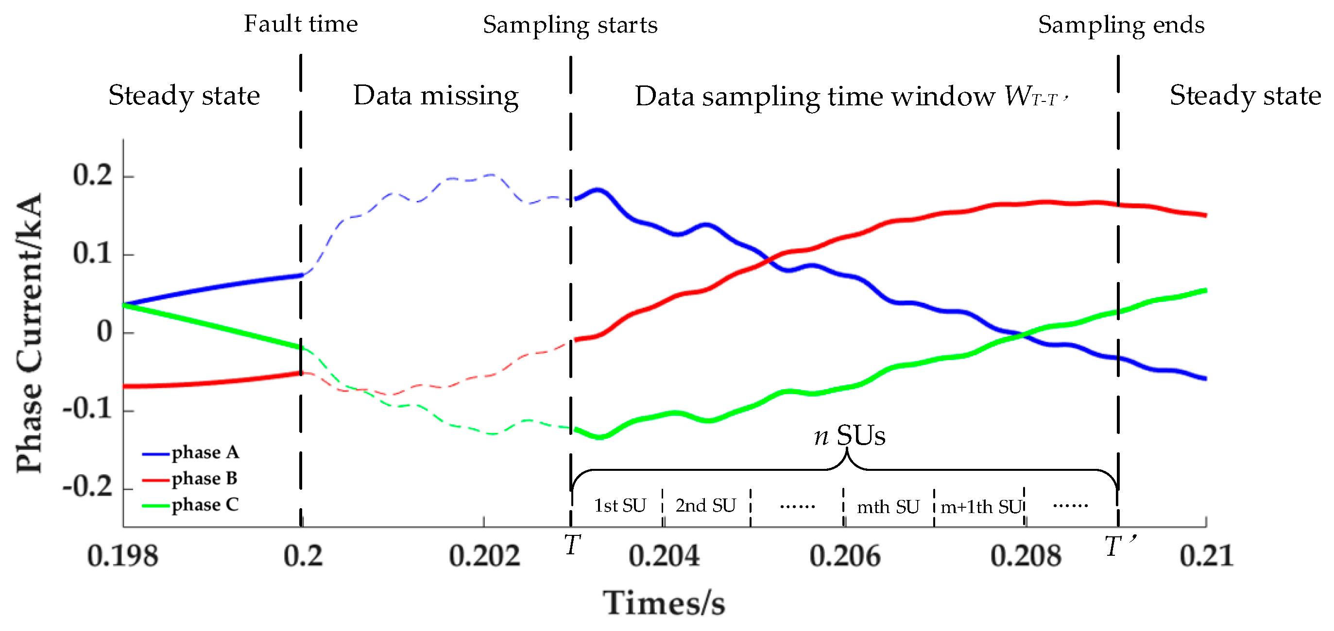
The faulty phase selection matrix (MOHD) based on an optimized HD algorithm (OHD) was first proposed in this paper. With the MOHD, the faulty phase selection time window can be determined adaptively. Suppose a SPG occurs in the distribution system, the transient data within T after the fault is missing, and the transient process ends at T’ after the fault. It therefore makes sense for transient fault data to be sampled from T to T’ after the fault. This valid data sampling time window is defined as .
The sampling process is divided into
n faulty phase selection units (SUs), each with a time duration of ms. For each SU, a data sequence of the three-phase current mutation will be synthesized, and then, the faulty phase selection will be completed. The above process will be repeated
n times, and there will be a continuous data sampling process. The transient data sampling time window is shown in
Figure 6.
In
Figure 6, a SPG occurs at 0.2 s, with a data loss of 0.003 s after the fault. At
T’ seconds after the fault, the fault transient process ends. The transient data sampling time window
is made up of
n SUs.
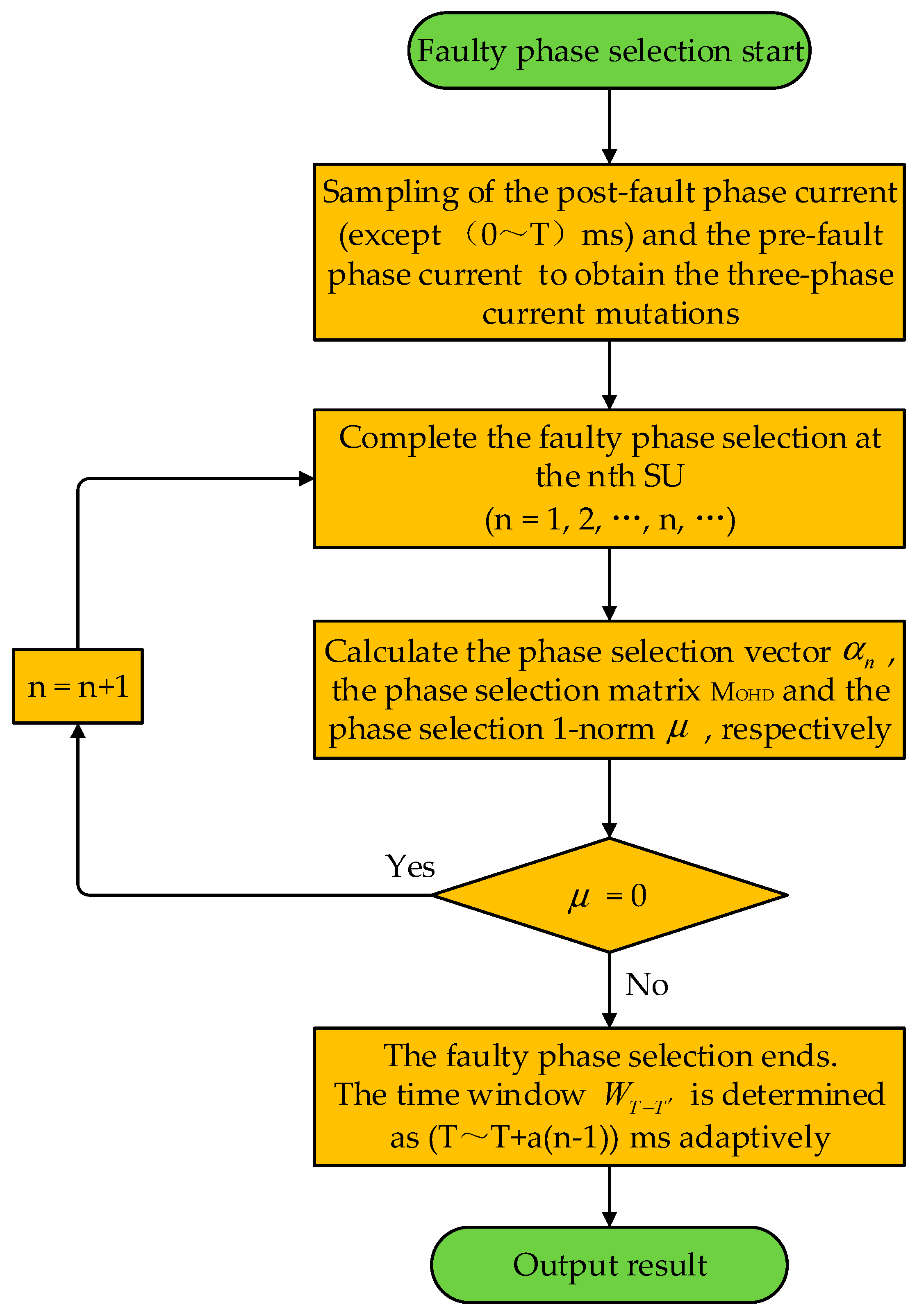
The faulty phase selection vector is set to represent the faulty phase selection result of the nth SU.
When the faulty phase is phase A, ;
When the faulty phase is phase B, ;
When the faulty phase is phase C, .
The matrix M
OHD is expressed by
The time window 1-norm
was set to indicate the consistency of the
and the
, which are expressed by
When
, this means that the
nth SU is still in
, and faulty phase selection continues in the
n + 1th SU. When
, this means that the
nth SU is already outside
, and the faulty phase selection process is complete. The flowchart of faulty phase selection based on M
OHD is shown in
Figure 7.
The time window WT−T’ is determined as from T to T + a(n − 1) after the fault. With the MOHD and WT−T’, the proposed faulty phase selection method can be adapted to different scales of the distribution system. The effect of the missing sampling data on the faulty phase selection results is also taken into account in this method. In addition, the WT−T’ can provide a reliable transient database for the rest of the transient-based relay protection methods.
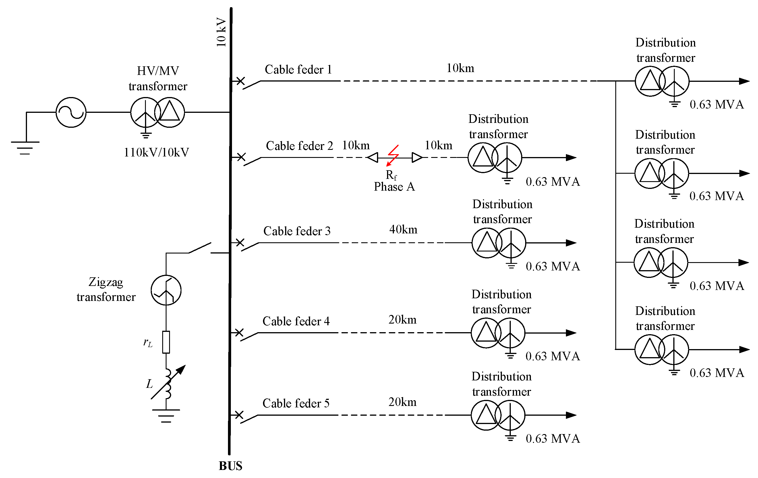
5. Simulation Verification and Results Analysis
In this paper, a typical medium voltage distribution system is modeled in a Power Systems Computer-Aided Design/Electromagnetic Transients, including the DC. The three-phase current mutation is collected in PSCAD/EMTDC, and the similarity coefficient is calculated in MATLAB. The distribution system model is shown in
Figure 8.
The parameters of the HV/MV transformer and the 10-kV feeder are shown in
Table 1 and
Table 2, respectively. The arc suppression coil is grounded through the secondary side of the zigzag transformer, and its equivalent inductance value is 0.1078 H. The distribution loads are connected to the end of the feeders with capacities of 0.39 + j0.18 MVA.
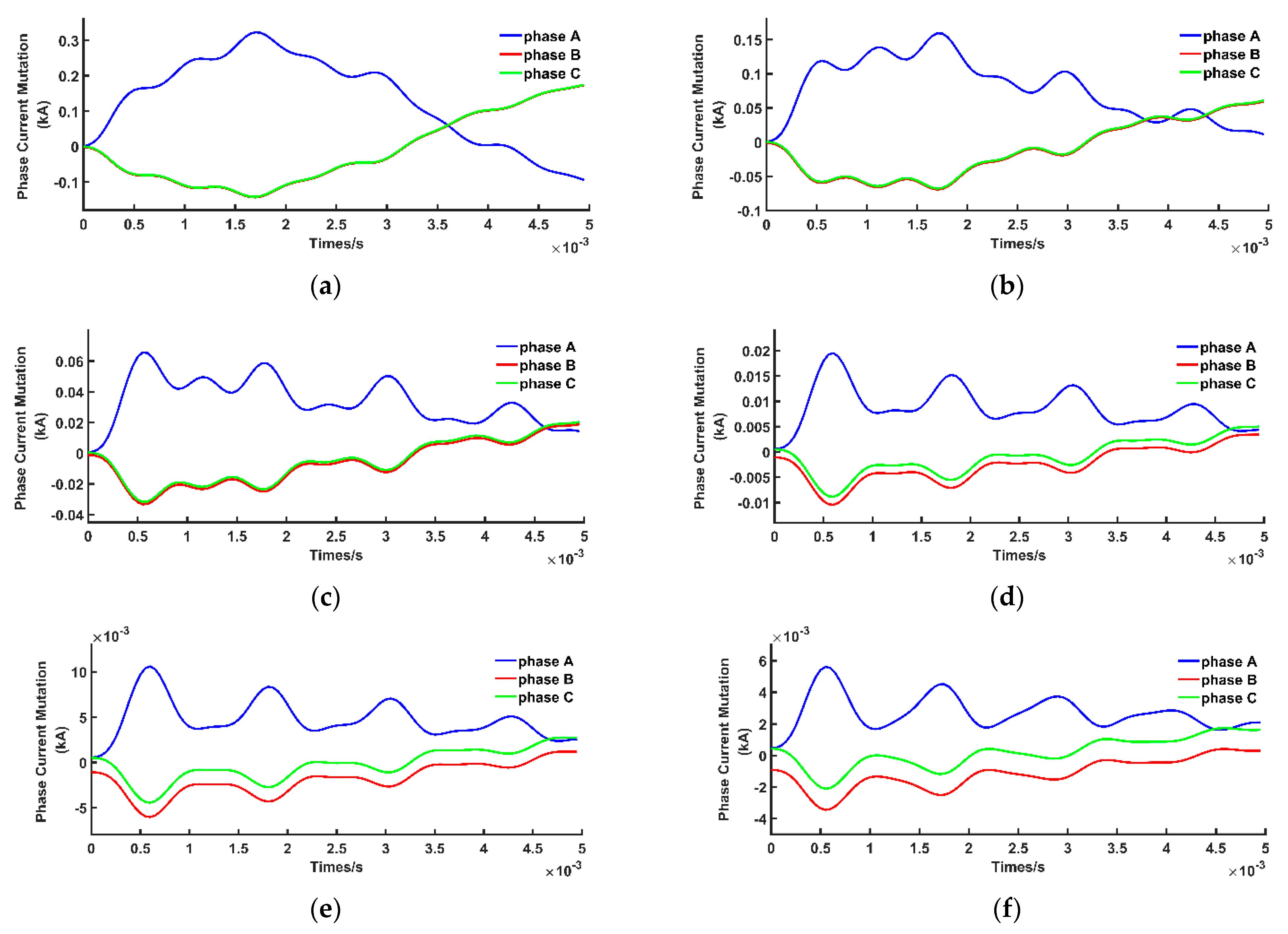
Suppose a SPG occurs in phase A of feeder 2 of the distribution system simulation model with a system sampling rate of 20 kHz. The fault inception angle of the voltage is 90°, and the fault resistance is 1 Ω, 25 Ω, 100 Ω, 500 Ω, 1000 Ω and 2000 Ω, respectively. After the SPG occurs, the waveforms of the phase current mutation in phases A, B and C are shown in
Figure 9.
As can be seen from
Figure 9, the phase current mutations in phase A, phase B and phase C all decrease gradually as the fault resistance increases. During this process, the differences between the phase current mutation waveforms of the faulty phase and the ones of the sound phase gradually decrease, and the difference between the phase current mutation waveforms of the two sound phases gradually increases. When the fault resistance is 1000 Ω and above, there is no situation where the difference between the faulty phase and the sound phase is more significant than the difference between the two sound phases, which increases the difficulty of faulty phase selection.
We calculated the similarity coefficient of the data sequence of the A, B and C phase current mutations through the Hausdorff distance algorithm in MATLAB. Then, we calculated the fault evaluation parameter and faulty phase selection standard. The faulty phase selection was completed, and the results are shown in
Table 3.
Table 3 shows that when the fault resistance varies from 1 Ω to 2000 Ω, the fault evaluation parameters
λA of the faulty phase A are all much greater than the faulty phase selection standard
λset. When the fault resistance is a constant value, the proposed faulty phase selection method based on the transient current similarity measurements correctly identifies the faulty phase A. In all cases, the sensitivity factors ε (
λA/
λset) exceeded 1.4, so the proposed method is effective in harsh environments.
Three sets of fault signals were collected in a real power distribution system in the Wenzhou area of China. The fault signals were collected in a fault indicator. The fault indicator was installed near the output of the substation with a sampling frequency of 4096 Hz. The performance of the proposed method was verified, and the results are shown in
Table 4. The faulty phase selection method based on the transient current similarity measurements proposed in this paper correctly selected the faulty phase in a real distribution system.
The three methods of faulty phase selection that are widely used in the field are listed as follows. The method proposed in this paper (Method 1) is compared with these three methods.
Method 1: The novel faulty phase selection method for SPG in a distribution system based on the transient current similarity measurements proposed in this paper.
Method 2: The phase with the lowest phase voltage is judged to be the faulty phase when a SPG occurs in a resonant grounded distribution system.
Method 3: When the system is in the overcompensation state, the phase leading to the highest voltage phase is the faulty phase, when the system is in the under-compensation state, the phase lagging the highest voltage phase is the faulty phase.
Method 4: The first half-wave method.
The first half-wave method has been widely used in faulty line selection, which was used to select the fault phase in this paper. The polarity standard is defined as
. When the polarity of the phase current is positive,
. When the polarity of the phase current is negative,
.
can be expressed by
is the
kth sample value of the fault current.
is the number of half-cycle sampling points. In the simulation model in
Figure 8, the fault resistance was set as 100 Ω and 2000 Ω, respectively. The distribution system was set up as a symmetrical system and an asymmetrical system, respectively, and the asymmetry of the system was set as 0% and −1.095%, respectively. The results of the faulty phase selection for Method 1 and the other methods are shown in
Table 5. The method proposed in this paper (Method 1) is able to select the faulty phase accurately, without interference from fault resistance, system compensation and system symmetry. When the fault resistance is high, Methods 2 and 4 will identify the sound phase as the faulty phase by mistake. Method 3 will identify the sound phase as the faulty phase in an asymmetrical distribution network.
7. Conclusions
When a high-resistance SPG occurs in a distribution system, the steady-state components of the fault signals are too weak to be used for faulty phase selection. The traditional faulty phase selection methods based on the power–frequency amplitude and phase characteristics have a complicated and unfeasible process. A novel faulty phase selection method based on the transient current similarity measurements is proposed in this paper.
The data sampling process has been divided into several faulty phase selection units (SUs). For each SU, the transient phase current mutation is synthesized from the difference in the phase currents before and after the fault. The HD algorithm is used to normalize the phase current mutations and calculate the waveform similarities of the transient phase current mutations among the three phases of the distribution system. The MOHD is synthesized based on the faulty phase selection results of the SUs. The phases where the fault evaluation parameter (λA,B,C) exceeds the selection standard (λset) are identified as faulty phases. With the MOHD, the proposed faulty phase selection method can be applied to any scale of the distribution systems, and the proposed method can be applied in cases where a small amount of sampling data is missing. After a theoretical analysis and simulation verification, the following two conclusions can be drawn:
When any SPG occurs in a typical medium-voltage distribution system, the proposed faulty phase selection method can accurately select the faulty phase over a wide range of fault resistances with a system sampling rate of 20 kHz and a time window of 5 ms. This method is still valid, even when the fault resistance reaches 2000 Ω or the fault resistance varies during the fault process. In all cases, the sensitivity factors ε (λA,B,C/λset), the ratio of the evaluation parameter of the faulty phase to the selection standard, all exceeded 1.4.
When the fault inception angle varies from 0° to 90°or the number of system feeders changes, the proposed method can select the faulty phase correctly. Although the similarity between the faulty phase and sound phase increases as the sampling time, the window changes from 1 ms to 10 ms, which raises the difficulty of faulty phase selection, and the proposed method can still accurately select the faulty phase. In addition, the proposed method is still valid when the missing rate of the sampled data is below 30%.


