Article

Comparative Numerical Study of the Influence of Film Hole Location of Ribbed Cooling Channel on Internal and External Heat Transfer

1
School of Mechanical Engineering, Pusan National University, Busan 46241, Korea
2
Department of Mechanical Engineering, Virginia Polytechnic Institute and State University, Blacksburg, VA 24061, USA
*
Author to whom correspondence should be addressed.
Energies 2021, 14(15), 4689; https://doi.org/10.3390/en14154689
Submission received: 5 June 2021 / Revised: 27 July 2021 / Accepted: 29 July 2021 / Published: 2 August 2021

Abstract

:
The influence of film-hole position on internal and external heat transfer was investigated using Computational Fluid Dynamics (CFD). A simplified geometry of an integrated configuration of a ribbed channel, film hole and mainstream passage is modeled to represent a turbine internal and external cooling scheme. The proposed configurations with nine different positions of film holes are parameterized to conduct a series of CFD calculations at a target blowing ratio of 0.8, 1.1 and 1.7. Since the present study is taking a comparative approach, CFX with SST models is applied as a primary tool and the results are compared with Fluent solver for selected cases (total 36 cases). Among the proposed nine positions, the film holes located in the separated flow region of a ribbed channel showed considerable enhancement in film effectiveness with minimum reduction and potential improvement in internal heat transfer. The finding offers a design opportunity to enhance internal as well as external heat transfer.

1. Introduction

Since cooled turbine airfoil was introduced for gas turbine application, there is a continuous effort to improve the performance of film cooling. Thanks to these efforts, novel and innovative designs of film holes are proposed and some are implemented in real applications. The early investigations [1,2,3,4,5] focused on a single film injected to the mainstream flow. The measured velocity field characterized typical interaction between film and mainstream flow such as lift-off and penetration of mainstream flow as a function of blowing ratio. The geometric parameters defining the shape and aligning angle of film holes were also found to be sensitive to the film performance. As an example, the ratio of length to diameter (l/D) significantly influences flow physics and film performance. It is reported that film performance improved as the l/D decreased from 4 to 1.75 [6].
In application of film cooling to a turbine airfoil, the position of the film hole is subject to the heat load on the turbine airfoil surface. Therefore, it is often determined irrelevant to the internal geometry of the cooling passage. Occasionally, the film hole intersects with rib turbulators. Since the flow through the internal cooling passage of the ribbed channel is highly vortical, the position of film extraction will also influence the interaction with mainstream flow, hence film cooling performance.
The influence of two film-hole positions (the middle and immediate downstream of a 90° rib) on the heat transfer of a ribbed channel was investigated experimentally [7]. Placing the film hole in the immediate downstream of the rib (at s/D = 1, the ratio of the distance between the film hole and rib to the hole diameter) enhanced the heat transfer as the flow accelerated in the vicinity of the extraction hole and also reduced the separation region in the downstream of the rib. It should be noted that the bleed flow rate was set at 1.25% per film hole for uniform bleed condition. Similar results were reported in a series of experiments on angled (60° and 90°) V and Λ shaped ribs at the bleed flow rate of 1.2% and suction ratio of 6 [8,9]. Among the proposed configurations, a film hole positioned in the immediate downstream (s/D = 4.5) of the ribs showed enhanced heat transfer compared with those in the middle of the ribs and upstream (s/D = 10.5) of the next adjacent rib. One exception was observed for a Λ shaped rib with the film hole positioned in the middle of the ribs. In this case, the trend was reversed so that the film hole in the upstream of the ribs showed higher heat transfer than others.
Furthermore, the influence of the film hole position relative to the rib on film effectiveness was measured in various combinations of a 45° rib and film-hole location [10]. The film hole also had a 45° compound angle and was positioned at s/D = 2~7. The results showed that the average effectiveness of the film positioned in the upstream of the rib was higher than the other two positions (middle and downstream of the rib) for a blowing ratio of 1.0 and 2.0. For the blowing ratio of 0.5, a film hole positioned in the middle of ribs showed the highest film effectiveness. However, there was no clear trend of film effectiveness from the different alignment of 45° ribs. Further measurements of the similar relative positions, the downstream (s/D = 1) and middle (s/D = 2) of 45° ribs, reported that the lateral average film effectiveness of the film hole in the middle of the ribs had the highest values for BR = 0.5, and 1.0. However, for BR = 2.0, the highest values were shown when the film hole was positioned in the downstream of the rib [11]. In another experimental study [12] on the configuration of a 60° rib with three film positions (downstream, middle and upstream of the rib), the regional average effectiveness increased as blowing ratio increased (BR = 0.4~0.8). Among the three relative positions (s/D = 1, 1.5, 2) of the film hole, the film positioned in the middle of the ribs (s/D = 1.5) showed the lowest film effectiveness.
There are still many remaining parameters to be investigated for better understanding of the internal and external heat transfer due to the relative position of the film hole. For this purpose, CFD will be a useful and economical tool prior to initiating a series of further experimental investigations.
Numerous studies on a simplified single film hole on a flat plate were implemented using Reynolds-averaged Navier–Stokes (RANS) equations [13,14,15,16,17,18,19,20]. While the RANS model can predict the fundamental flow structure of a counter-rotating vortex pair as film flow interacts with mainstream flow, it typically underpredicts its spanwise spreading. However, RANS is practical in many cases because of its relatively low computational efficiency and cost. On the other hand, the large eddy simulation (LES) can predict the detailed vortical structures such as a counter-rotating vortex pair, horseshoe vortices, spiral vortices [21] and hairpin vortices [22]. In addition, LES performs well in predicting the spanwise and centerline adiabatic effectiveness as it captures the trajectory and spanwise spreading of film correctly [23]. LES simulates turbulent mixing driven by the shear of mainstream and film flow more accurately [24]. Turbulent eddies are highly anisotropic, and the length scales of small eddies decrease near the wall. Therefore, finer mesh is required for LES, which will demand more computational time. Another possible approach is to implement the LES wall model, but it would not be accurate enough to handle complex flow [25]. Detached Eddy Simulation (DES) is a reasonable alternative as it implements both LES and RANS for tackling high speed and complicated flow [26]. Such a hybrid approach was applied to resolve the structure of film-flow interaction with mainstream flow [27,28]. The capability of the high-fidelity CFD approaches such as LES and DES has been demonstrated in many applications. However, it is still challenging to adopt the tools as a part of an industrial design process.
While, the previous studies focused only on film performance or the internal heat transfer of a ribbed internal cooling channel, the present study aims to evaluate the influence of film-hole location on internal as well as external heat transfer. The total nine locations of the film hole (4 < s/D < 22) were selected for comparative study, while a simple cylindrical shape was kept for film hole geometry. For the internal cooling channel, 45° ribs are positioned on the top and bottom walls. The flow control parameters for internal and external heat transfer are (1) blowing ratio of film and (2) Reynolds number of ribbed cooling channels. For this purpose, a parametric geometry was produced for conducting the series of mesh generation and analysis. Additional studies on the sensitivity of mesh density, RANS solver and the turbulent model were conducted to demonstrate the validity of the computational approach for the present study.

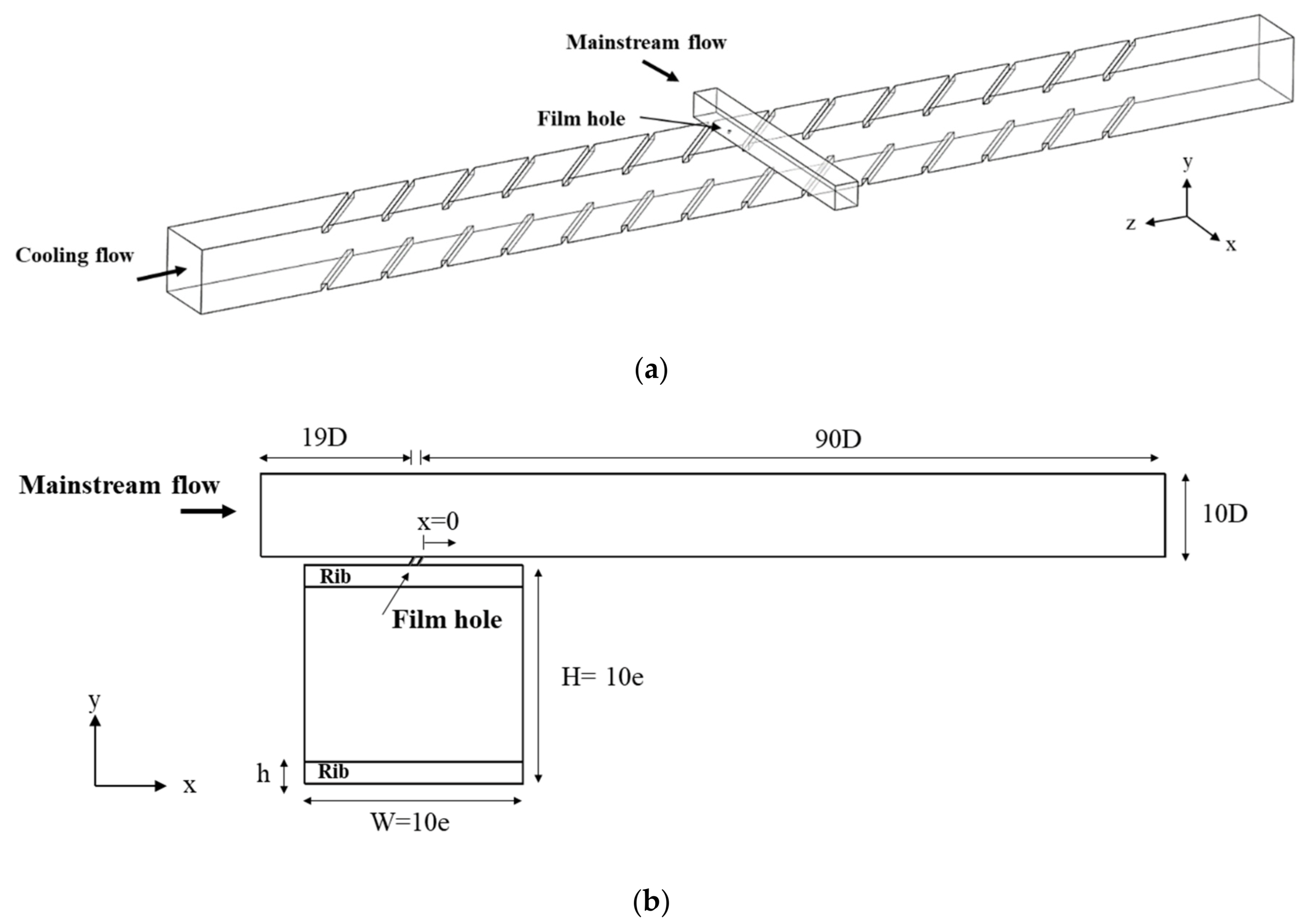
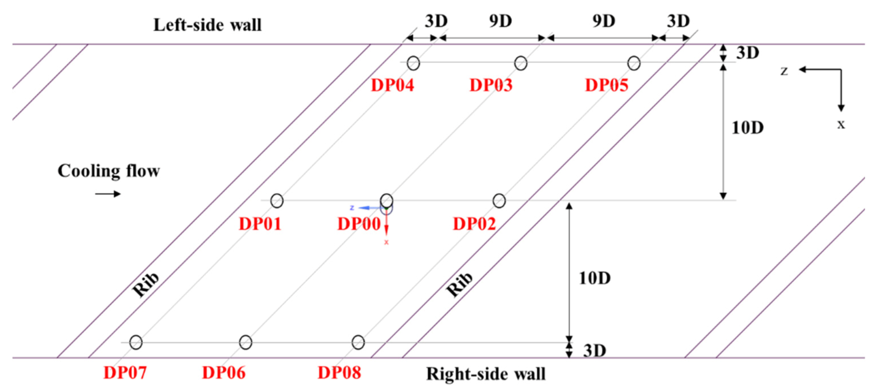
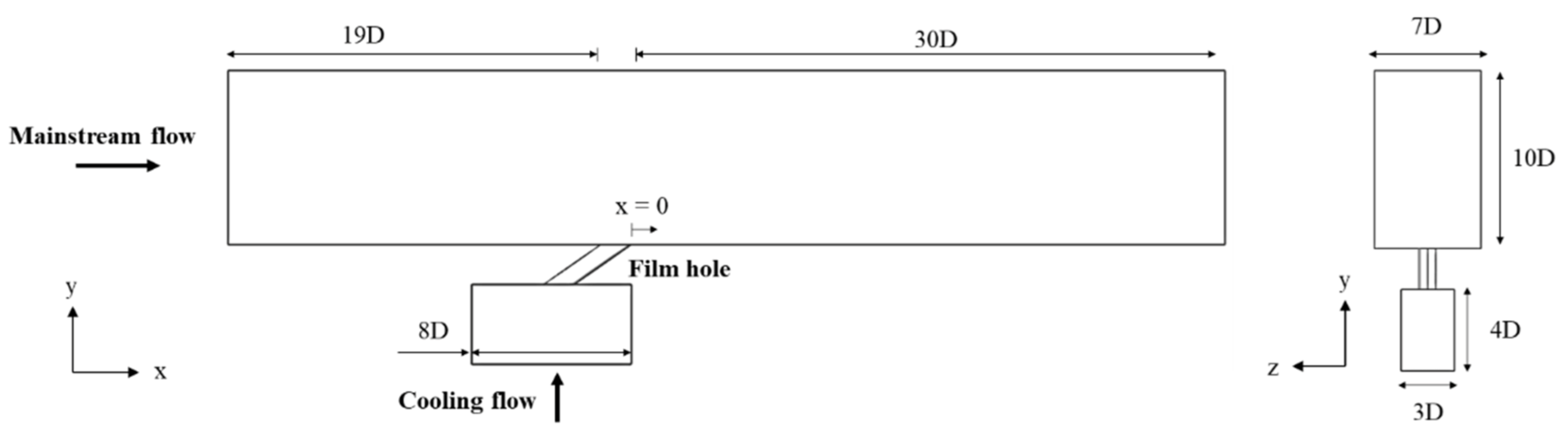
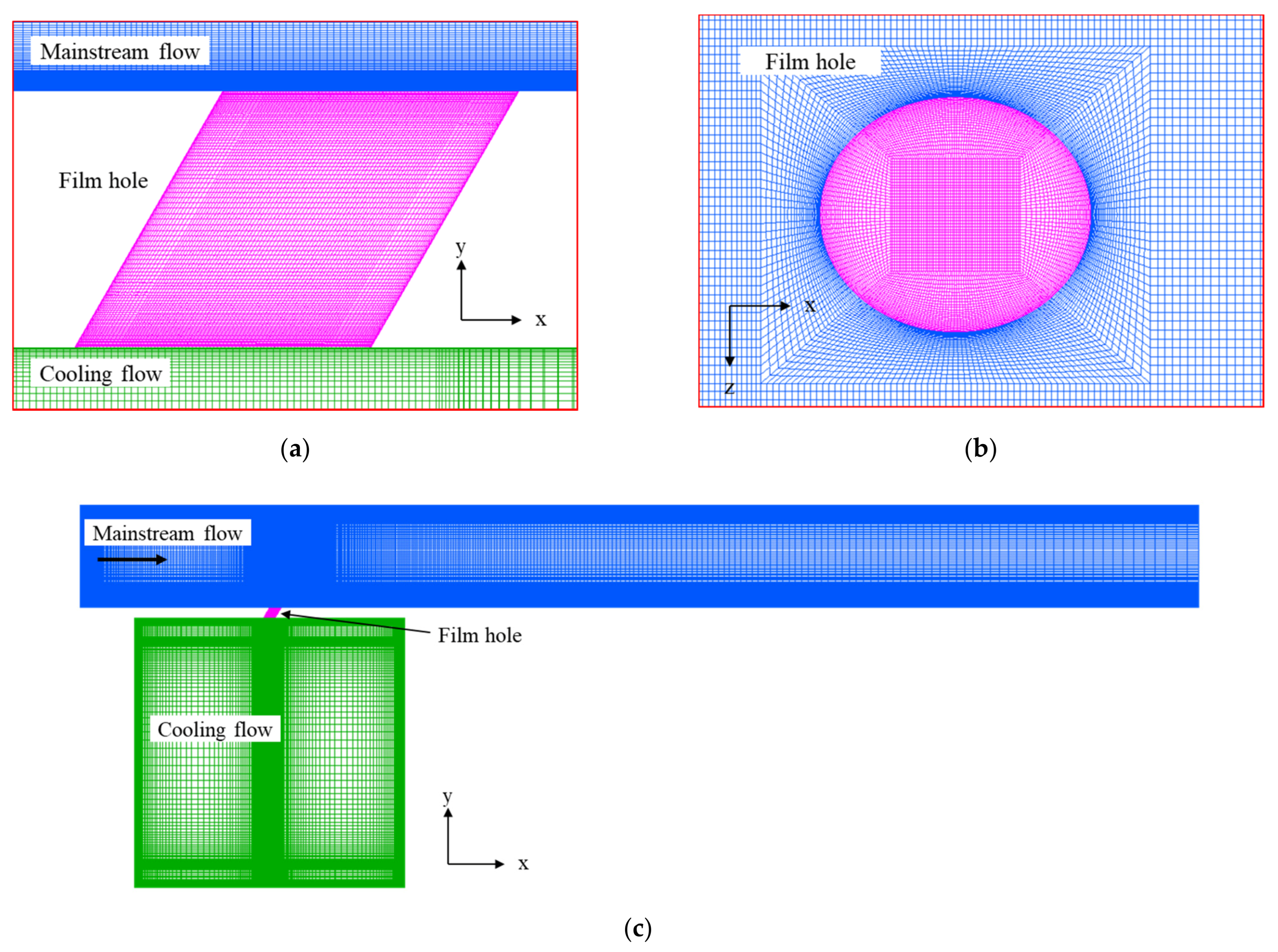
2. Geometry and Computational Model

A simplified analysis model representing the ribbed internal cooling channel and the mainstream passage of external turbine airfoil flow connected by a cylindrical film hole is shown in Figure 1, and the details of geometrical parameters are listed in Table 1. The ribbed channel has a total of 13 rib segments with smooth entrance and exit regions. In the 7th rib segment from the inlet, a cylindrical film hole is positioned to extract cooling flow to the mainstream flow (representing external airfoil passage).
For comparative study, the position of the film hole is varied as shown in Figure 2. A total of 9 positions are proposed to represent possible relative locations. Although the film hole may intersect with the rib directly, such a case is not considered for the present study. The film position of DP00 is the reference for comparison, and others (DP01~DP08) were selected to estimate its influence on the internal as well as the external heat transfer. DP01, DP04 and DP07 represent the film holes positioned in the downstream of the rib, while DP02, DP05, and DP08 are positioned in the upstream of the rib. For both, the distance from the rib, s is 3D. DP00, DP03 and DP06 are positioned in the middle of the rib. These nine positions are a reasonable representation of realistic intersection scenarios. Similar positions have been investigated by Böttger et al., [9] with the focus on internal heat transfer only.
For CFD, hexahedral mesh is generated by using Ansys Meshing (version 19.2 R2, ANSYS Inc., Canonsburg, PA, USA). The details of surface mesh are presented in Figure 3. The near wall mesh is highly dense to ensure that y+ values are smaller than 1.0 to capture the growth of the boundary layer. For calculation, the selected mesh size is a total of 58.2 million elements (14.6 million for external flow passage as well as the film hole, and 43.6 million for the ribbed channel) based on the mesh sensitivity study.
For boundary conditions, total pressure and temperature are set at the inlet of mainstream and ribbed channel flow, and pressure outlet for its exit. The pressure at the inlet of the ribbed channel is adjusted to achieve target blowing ratios (BR) of 0.8, 1.1 and 1.7 (the equivalent bleed flow rates are 0.58%, 0.35%, 0.33%, and suction ratios are 2.0, 1.4, 1.2), while the inlet pressure of the mainstream flow is kept constant. Regarding heat transfer, constant wall temperature is applied to the ribbed channel and the adiabatic wall for the mainstream domain. Table 2 summarizes the boundary conditions.

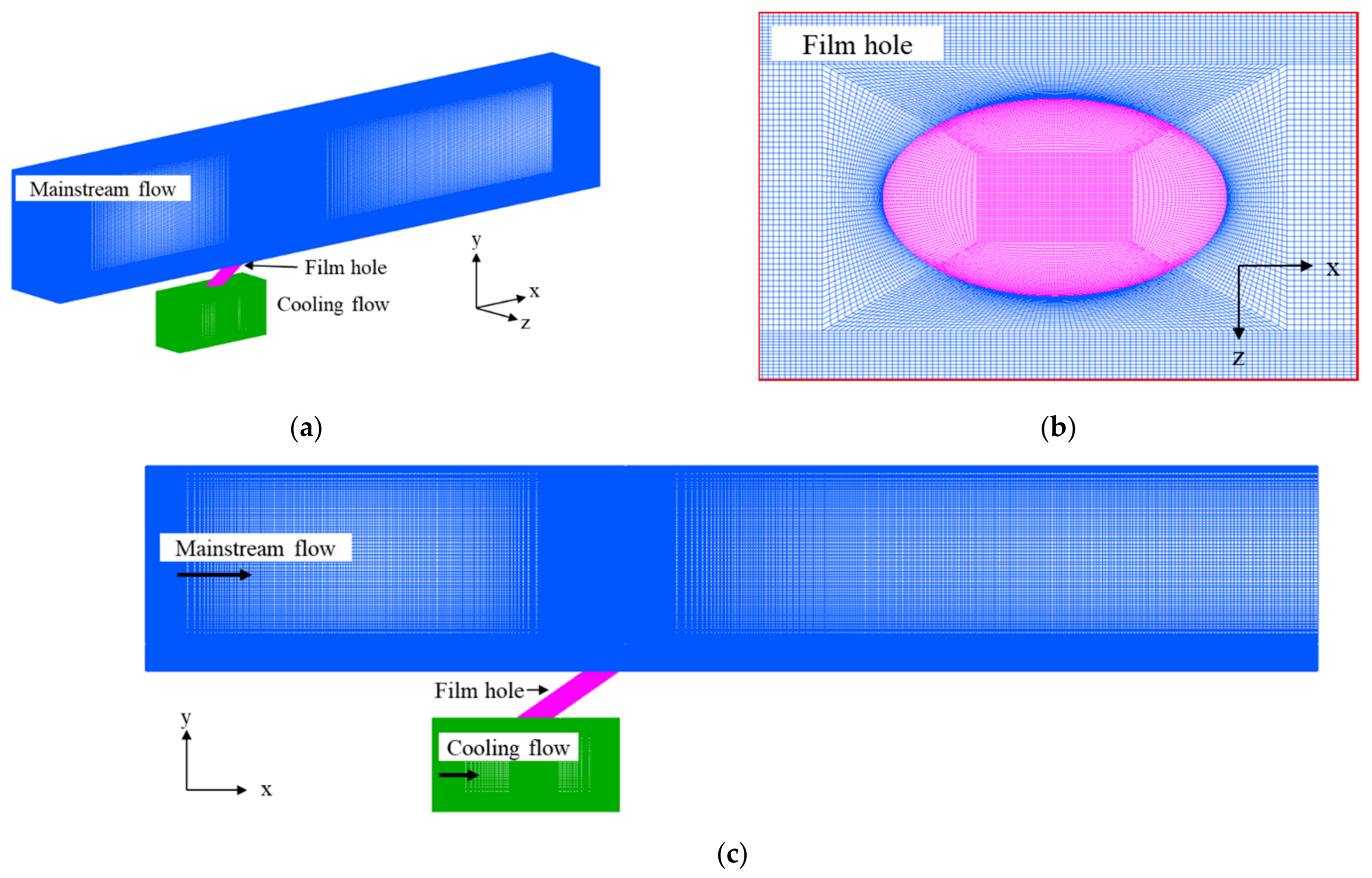
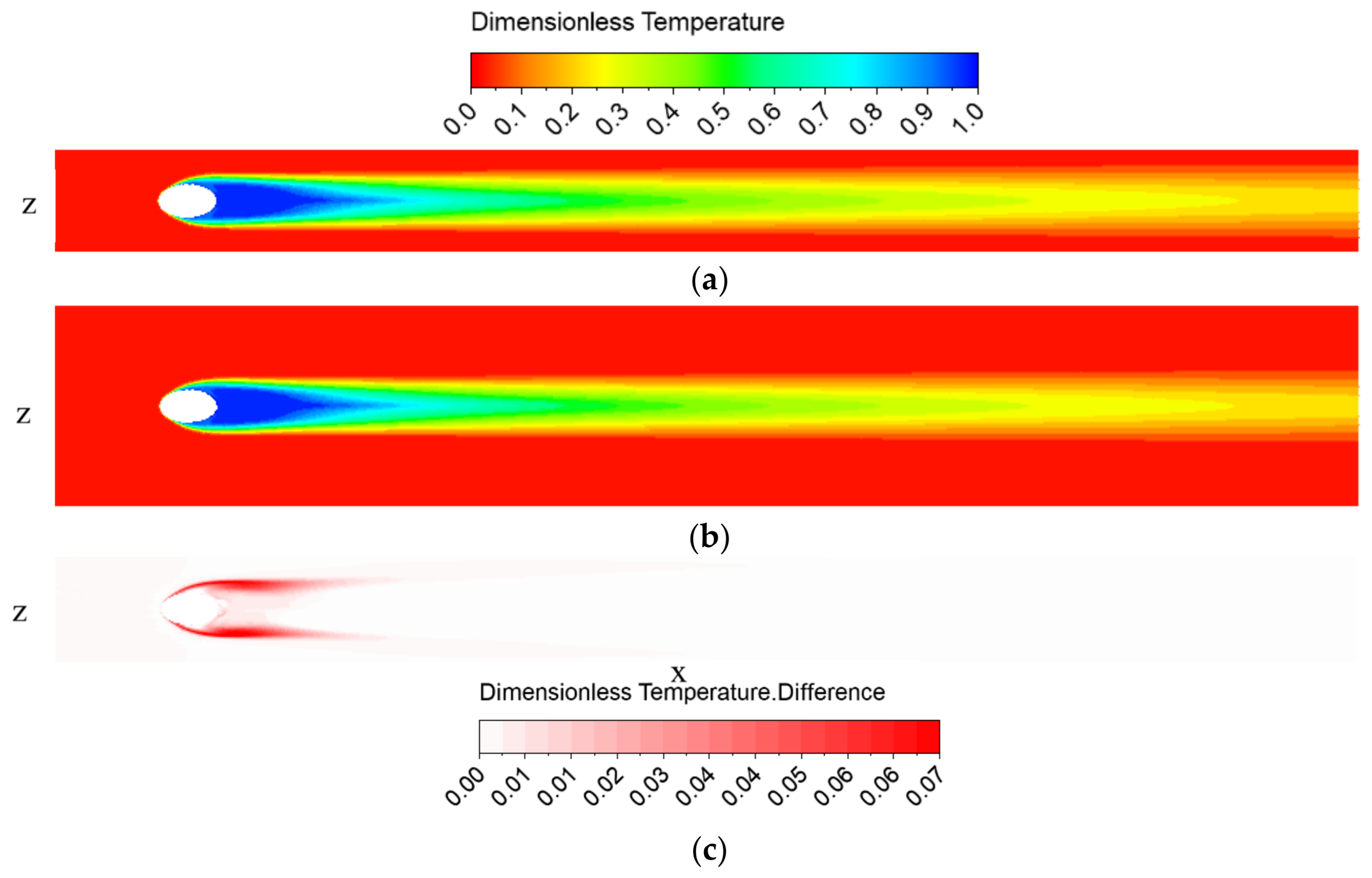
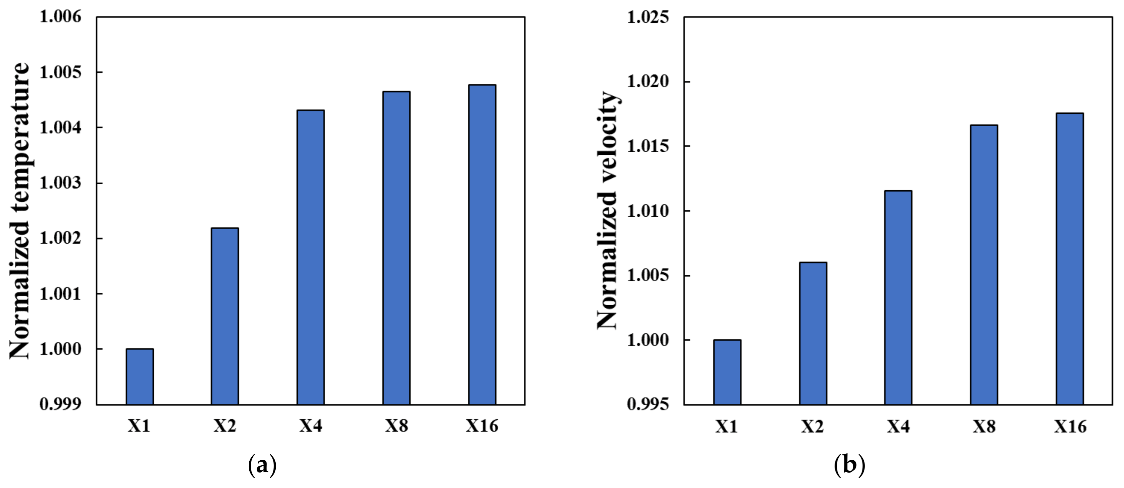
3. Mesh, Solver and Turbulence Model Sensitivity

For the validity of the mesh density and turbulence model, further CFD calculations were carried out prior to the study on the influence of the film-hole position. Two CFD solvers of Ansys (CFX and Fluent, Version 19.2 R2, ANSYS Inc., Canonsburg, PA, USA) were used for comparison, and a pressure-based coupled solution scheme was applied. The geometric configuration and boundary conditions were based on the experiment of Sinha et al. [6] as shown in Figure 4. The inclination angle of the film hole was 35° to the mainstream flow, and the cooling flow was fed from the bottom of the plenum. Figure 5 shows the computational domain and selected hexahedral mesh for the analysis. The convergence criterion was set to achieve the minimum RMS residuals of 1 × 10⁻⁴; however, the iterations were continued until the residuals were fully stabilized.
As a part of the sensitivity study, the effect of width of the mainstream flow domain was also investigated. As shown in Figure 6, the dimensionless temperatures, Equation (1) near wall are compared between the 3D and 7D widths of the mainstream flow domain. The difference looks very minimal referring to Figure 6c; however, it was clearly observed that the case of the 3D width confines the downstream flow as observed in Figure 7. As the result, the width of the mainstream flow domain of 7D was selected for the rest of the analysis.
D i m e n s i o n l e s s   T e m p e r a t u r e = T T c T c T m
where, Tc is coolant inlet temperature and Tm is mainstream inlet temperature.
To investigate the sensitivity of mesh density, six different sizes of mesh were produced as listed in Table 3. X1 is baseline mesh and X2 represents its double size. It is well understood that the interaction of film and mainstream flow is governed by the density ratio (DR) and the blowing ratio (BR). The definitions are:
DR = ρ j ρ m ,   BR = ρ j u j ρ m u m
where, ρj is density of cooling jet, ρm is density of mainstream flow, uj is velocity of cooling jet, um is velocity of mainstream flow.
Among the available data (Sinha et al. [6]), the measurements of DR = 2.0 with BR = 0.5 and 1.0 were compared with present predictions. Figure 8a shows the centerline adiabatic effectiveness, which is defined as:
η = T a w T m T c T m
where Taw is adiabatic wall temperature. For present calculation, the near wall temperature is used.
For BR = 0.5, the prediction using Fluent solver with realizable k-ε model (X8) matches with the measured data better than CFX solver with SST model. It should be highlighted that the increase in mesh density (X8) improved prediction compared with coarser mesh (X1) as shown in Figure 8a, but only for the immediate downstream region of film (x/D < 5). For further downstream of x/D > 10, the prediction using the coarser mesh (X1) followed the measured data well. It is also interesting to observe both CFX and Fluent solvers with the SST model largely overpredict the centerline effectiveness for most of the region. Among the predictions of CFX and Fluent solvers with SST model at different mesh densities, CFX solver show little difference compare to Fluent solver. As the BR increases to 1 (Figure 8b), the none of the combinations of the selected solvers and turbulence models did a good job, especially for the immediate downstream (x/D < 5) of the film hole. Only Fluent solver with realizable k-ε model started following the trend after x/D > 6 and eventually matched the values after x/D > 15.
To investigate further, adiabatic effectiveness and 3D vorticity structures colored by dimensionless temperature are compared in Figure 9 and Figure 10. For BR = 0.5, it is observed that the Fluent solver with realizable k-ε with higher density mesh (X8) predicted smaller flow separation at the entrance of the film hole and also the shear region at the immediate exit of the film hole than the SST model. For the same size of mesh density (X8), the calculations using two turbulence models of realizable k-ε and SST showed recognizable differences in predicting 3D vorticity structure. From the prediction using CFX solver with SST model (Figure 9c), there were also noticeable differences in 3D vorticity structure and its size compared to the Fluent solver. The similar trend in predicting 3D vorticity structure can be seen for BR = 1 (Figure 10) as well. In comparison of Figure 10b,c, CFX solver with SST model predicted the larger vorticity structure better than Fluent results. The additional separation at the upstream edge of the entrance of the film hole is seen only with Fluent solver (Figure 10a,b).
From above, it is obvious that density of mesh is strongly influencing the prediction. Furthermore, Figure 11 shows comparing normalized temperature at the film-hole exit and velocity at the film-hole inlet among the six different mesh densities. Beyond the mesh size of X8 (eight times denser than baseline, X1), it is clearly observed that the monitoring parameters are converging. Therefore, the mesh density of X8 was selected for the rest of the analysis.
Regarding the selection of the solver and turbulence model, no obvious conclusion can be drawn from the observation. The realizable k-ε model works better than the SST model for BR = 0.5 but not for BR = 1.0; it only follows the trend after x/D > 6 and matches the values after x/D > 15. Therefore, CFX with both SST and Fluent with realizable k-ε models were applied to investigate the influence of film hole position for comparison purpose.

4. Results and Discussion

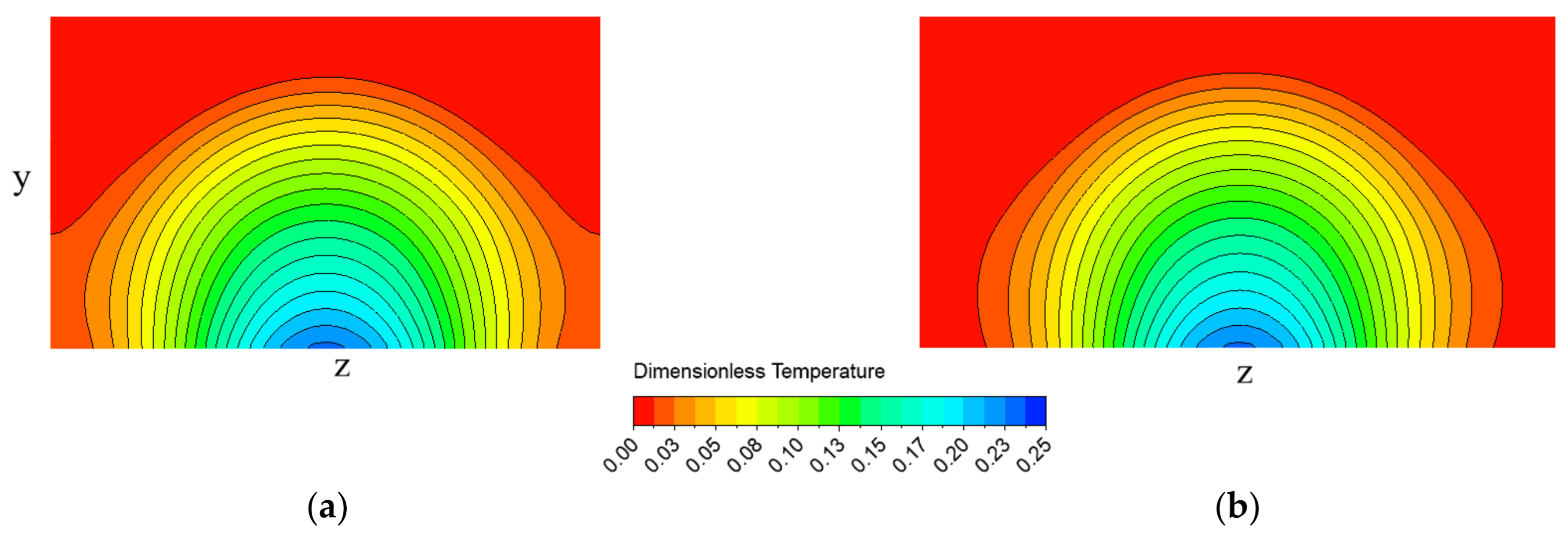
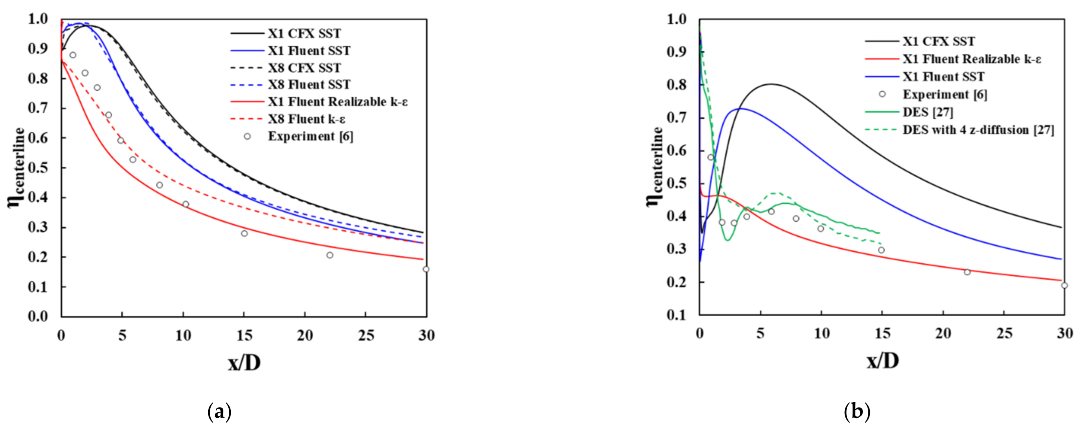
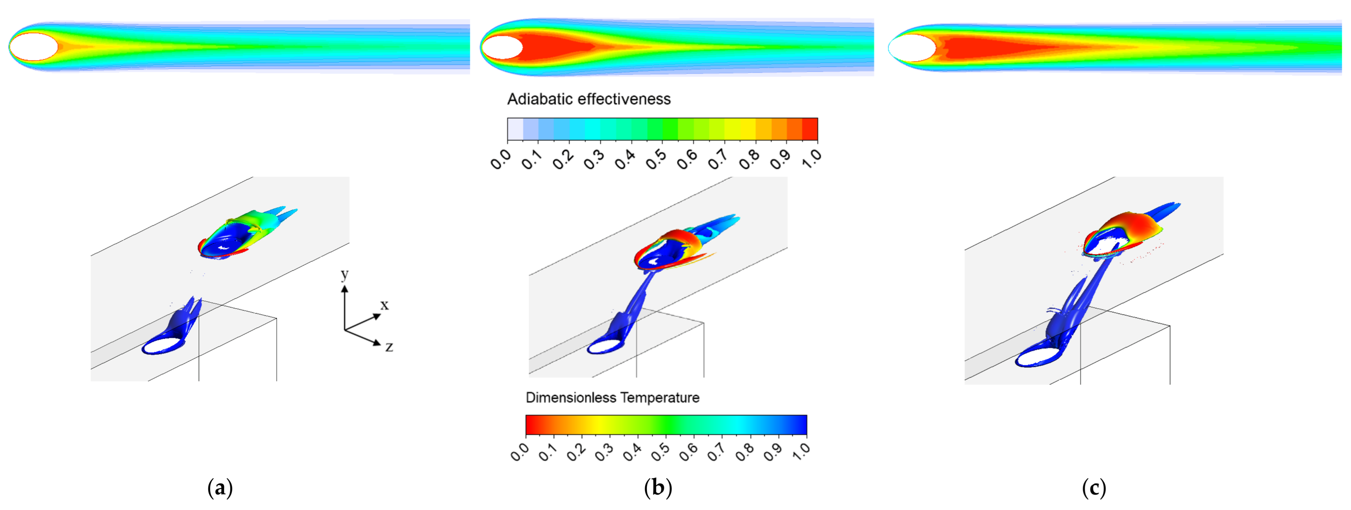
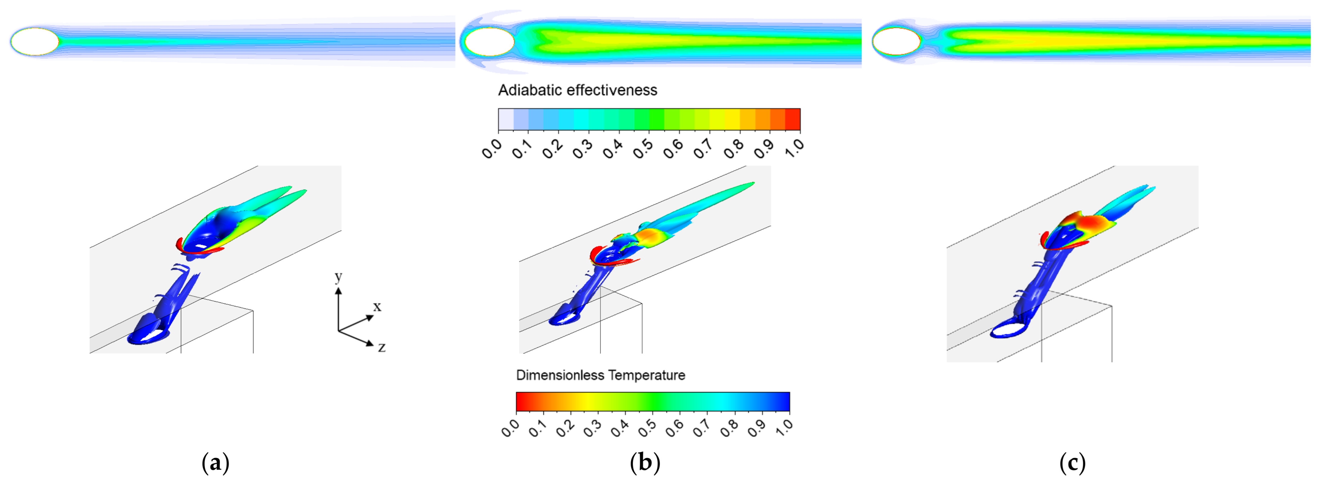
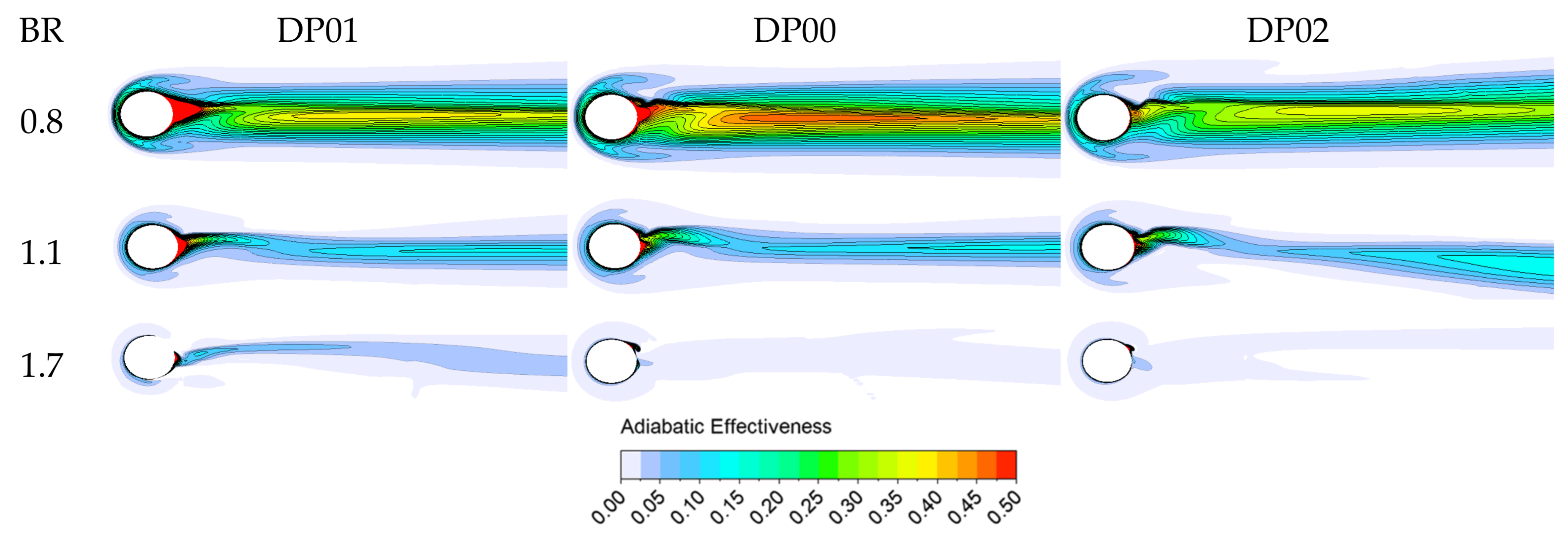
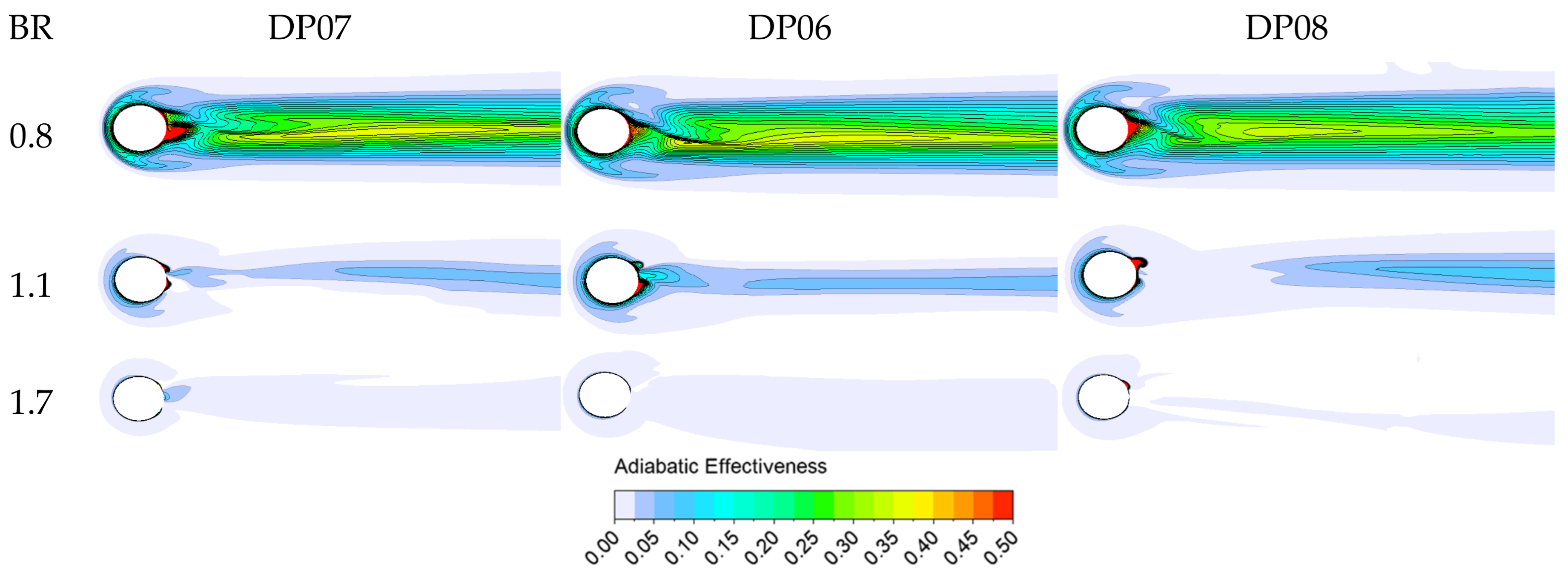
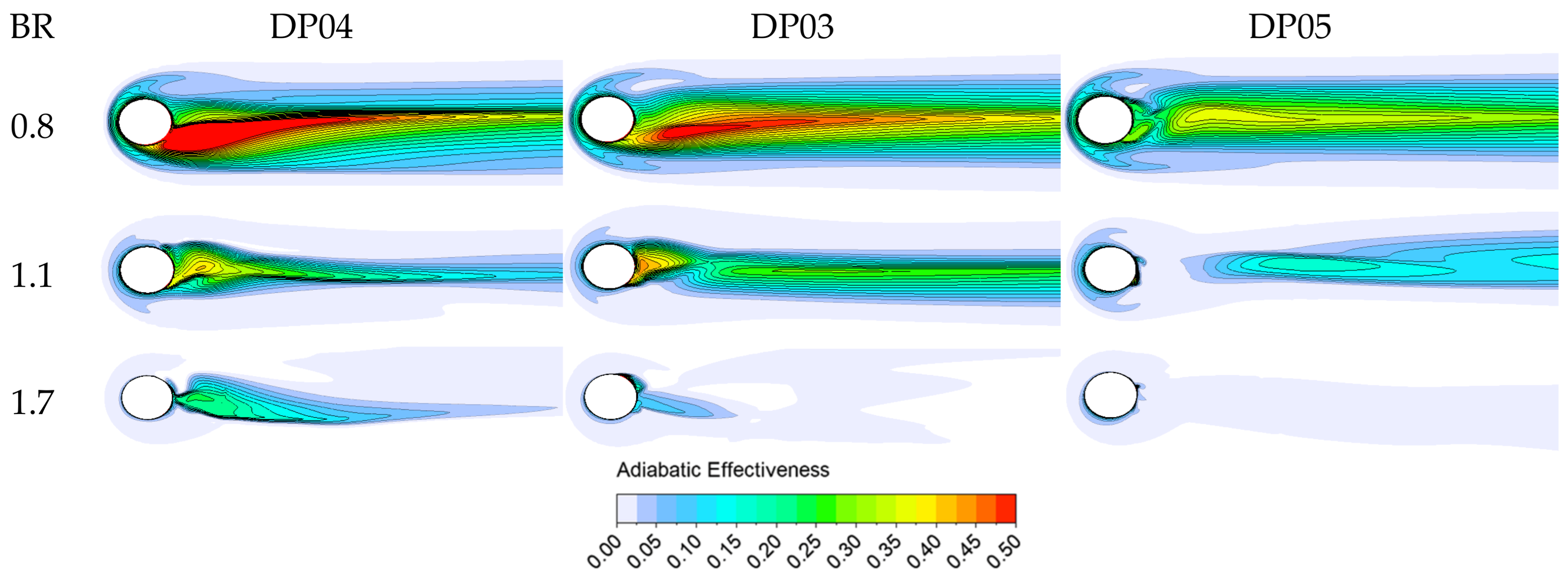
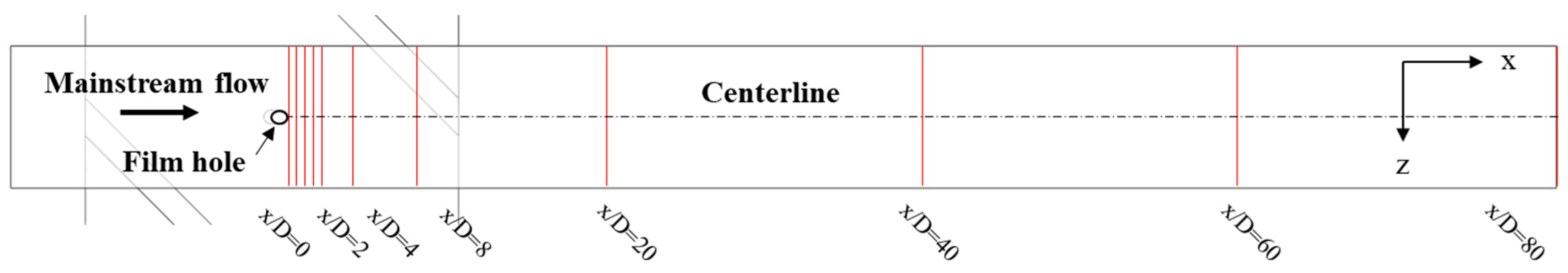
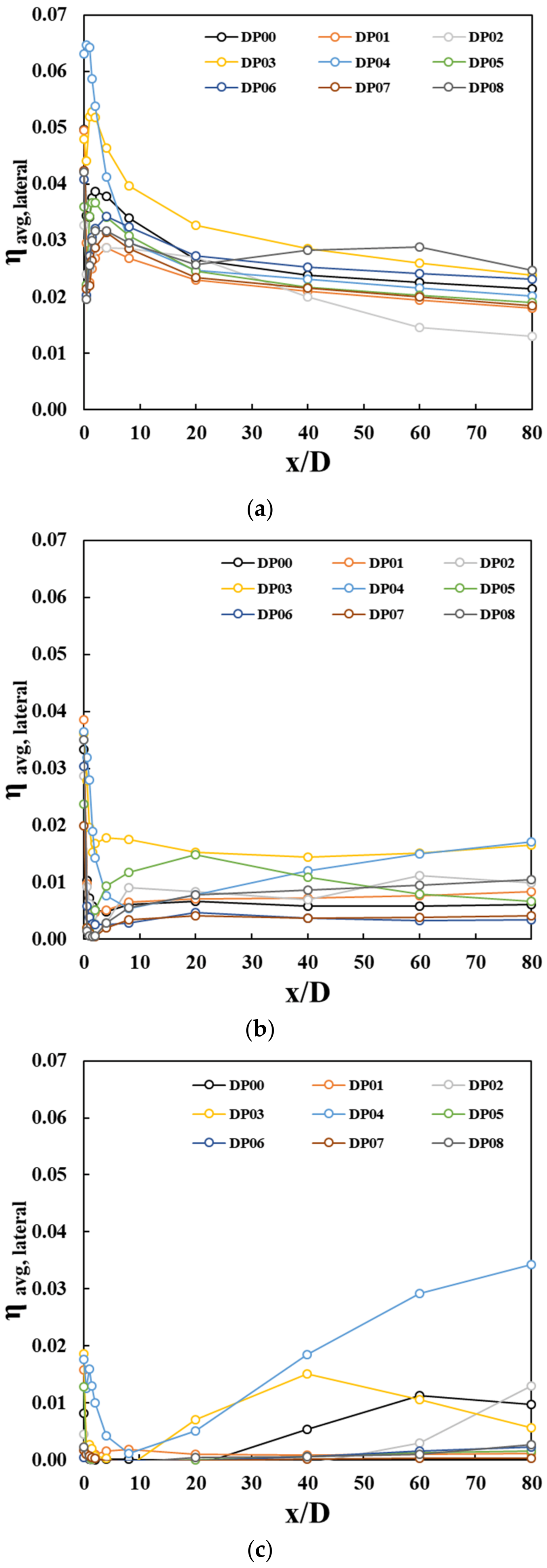
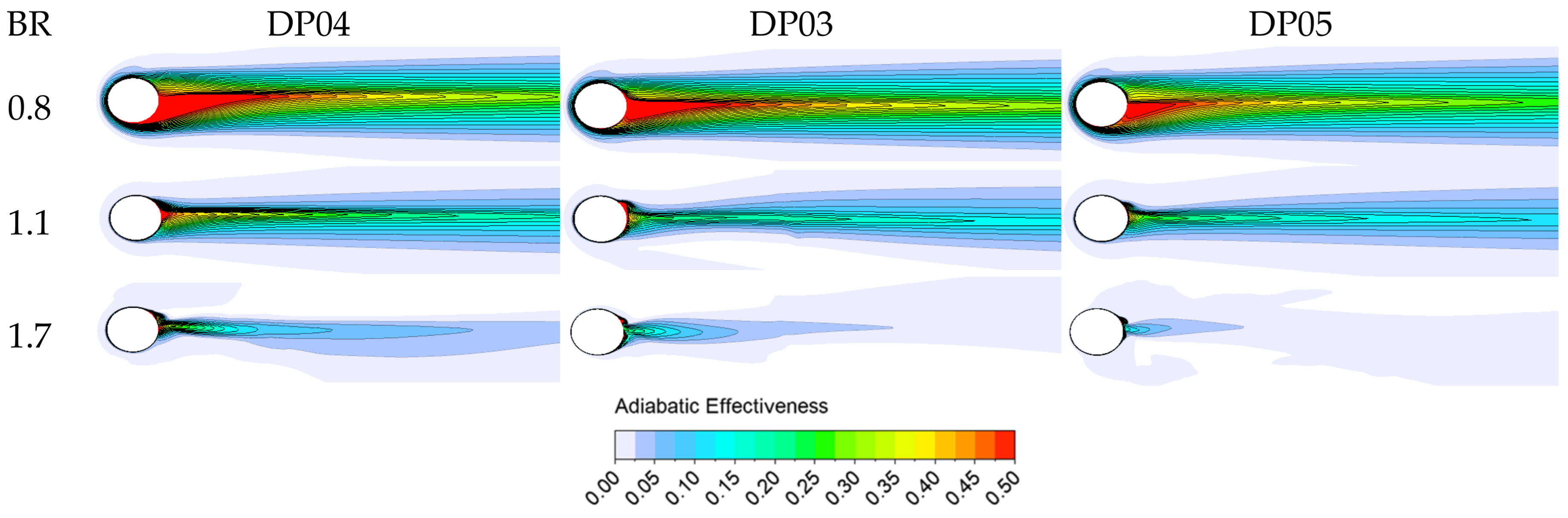
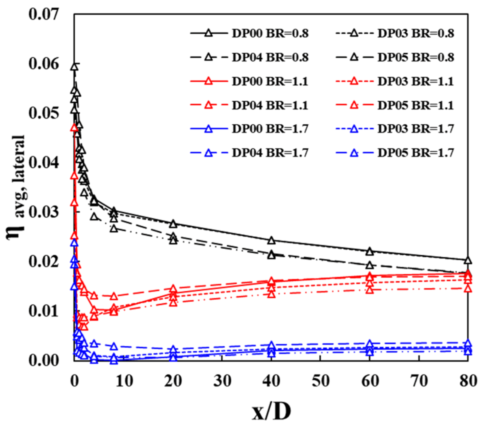
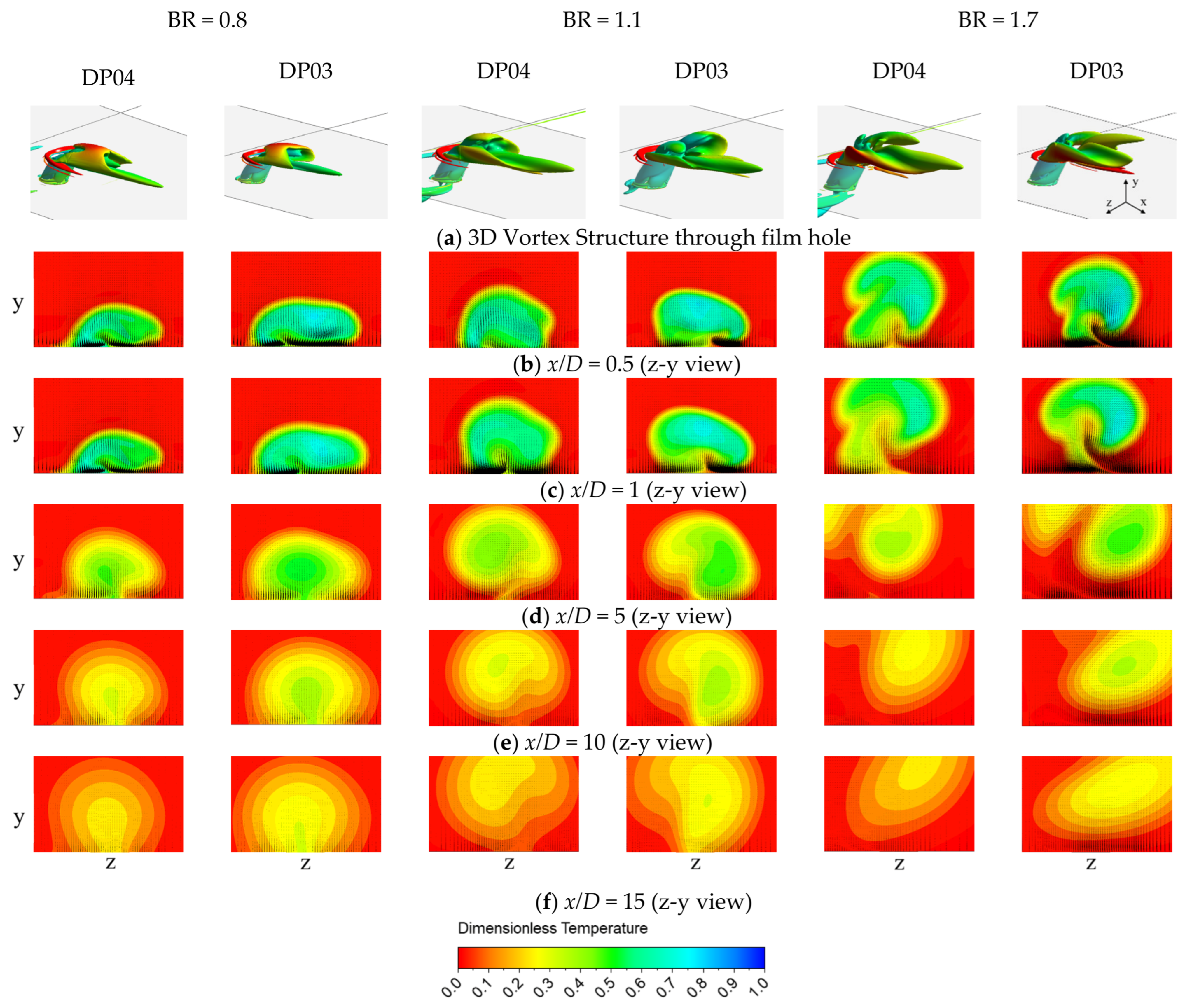
4.1. External Film Heat Transnfer

The nine positions of a cylindrical film hole in the 7th rib segment for the present study is shown in Figure 2. The boundary condition of the inlet of the ribbed cooling channel is adjusted to achieve target blowing ratios (0.8, 1.1 and 1.7) of the film hole positioned at DP00 while the boundary condition of the mainstream flow is fixed. Therefore, it is expected to see some variation of blowing ratio among the nine positions of film holes at each target blowing ratio. Figure 12 shows these variations of the blowing ratio of each film-hole position. It is noticeable that the trend of blowing ratios of film holes close to the left-side wall (DP03, DP04 and DP05) are reversed compared to the film holes in the middle (DP00, DP01 and DP02) as well as those close to the right-side wall (DP06, DP07 and DP08). For the target BR = 0.8, 1.1 and 1.7 referenced to DP00, the variations are in the range of +19%~−15%, +30%~−14%, +42%~−16%, respectively. Since film effectiveness is sensitive to blowing ratio, its influence is expected to be observed in film cooling performance.
In Figure 13, Figure 14 and Figure 15, the distribution of adiabatic effectiveness of each film location at three different blowing ratios is compared. Figure 13 presents the effectiveness of three film holes positioned in the middle of the ribbed channel, DP00, DP01 and DP02. The distribution shows non-symmetric contours as the flow though the film hole is highly distorted by the effect of the vortical flow structure of the ribbed channel. As blowing ratio increases, the flow through the film hole lifts off so that there is less film coverage in the downstream region. The overall trend is similar for the other film positions shown in Figure 14 and Figure 15. However, the level of film effectiveness of DP03, and DP04 positioned close to the left-side wall is higher than others. Even at the blowing ratio of 1.1, the two film holes perform better. At the highest blowing ratio of 1.7, all three films lift off eventually.
Therefore, centerline values are not meaningful for quantitative comparison due to the non-symmetric distribution of adiabatic effectiveness. Instead, laterally averaged values of effectiveness (locations are shown in Figure 16) are compared as shown in Figure 17. It is clearly seen that DP03 and DP04 are showing outstanding variations among the nine film hole locations. For BR = 0.8, DP04 shows the highest effectiveness locally, x/D < 2, but it achieves the best performance over the entire region for BR = 1.7. However, the trend is changed for BR = 1.1. DP03 records higher values for the most of the region except the immediate downstream of the film hole, x/D < 1.5. DP04 shows higher effectiveness than DP03 in the region of x/D < 1.5 (refer to Figure 15). Overall, DP04 records the highest effectiveness for BR = 1.7, and DP03 shows promising performance for BR = 0.8 and 1.1.
For comparison purposes, the predictions using Fluent solver are also presented in Figure 18. The Nusselt number distributions are not quite similar in trend as well as level compared to the CFX solver (refer to Figure 15). As shown in Figure 19, the laterally averaged values show very monotonic variation only by the effect of blowing ratio unlikely what has been observed from the prediction using CFX solver.
As noted earlier, there is high vortical flow in the ribbed channel. The 3D vortex structure shown in Figure 20a provides evidence of the swirling flow at the entrance of the film holes of DP03 and DP04. To investigate further on the characteristics of DP03 and DP4, especially for the interaction between the mainstream and film flow, the dimensionless temperature (Equation (1)) contours at various streamwise locations are observed as shown in Figure 20b–f. First of all, the concentration of film flow in the downstream can be clearly seen together with its interaction with mainstream flow. For BR = 0.8 and 1.1, the radius of film flow of DP04 is smaller and well-attached to the surface compared to DP03, but it is diluted earlier (1 < x/D < 5) than DP03. For BR =1.7, both films lift off immediately. Referring to Figure 12, the individual blowing ratios of DP04 are higher than DP03 at BR = 1.7; therefore, it is observed that the film flow of DP04 lifts off faster than DP03.
The regionally averaged value of adiabatic effectiveness is also compared in Figure 21. The overall trend shows that the effectiveness is decreasing as blowing ratio increases. DP03 is showing enhanced performance among nine positions for the given blowing ratio. The performance of DP04 is still strong except for BR~1.5, while DP05 shows improved performance in the specific blowing ratio of 1.5. This confirms that the DP03, DP04 and DP05 located close to the left-side wall have potential to achieve enhanced film effectiveness.
Discharge coefficient is one of the important parameters for designing the film hole and to characterize the film performance. The discharge coefficient ( C d ) is the ratio of the ‘ideal’ mass flow rate ( m i ˙ ) and actual flow rate ( m a ˙ ) through the film hole:
C d = m a ˙ m i ˙
The ideal flow is based on an isentropic, one-dimensional expansion of the cooling flow from the ribbed channel total pressure, pt, to the main flow static pressure, ps. For the present study, this ideal mass flow was calculated using the Bernoulli equation [29]:
m i ˙ = A 2 ρ p t p s
where, A is area, ρ is density.
Figure 22 shows the distribution of the discharge coefficient of the film hole at each position as blowing ratio varies. The results are also compared to the measured data with and without the rib (smooth channel) [30,31]. The clear difference is that the discharge coefficients of nine film holes are less sensitive to the blowing ratio in the range of 0.5~2.5. It should be noted that the ratio of rib pitch to hole diameter (p/D) of the selected references [30,31] is 4, which is much smaller than the present configuration, p/D = 26.3.

4.2. Internal Heat Transfer of Ribbed Channel with Film Extraction

It is reported that film extraction in the ribbed channel promotes heat transfer locally. Hence, the position of the film hole will influence the internal heat transfer. Figure 23 compares the normalized Nusselt number of ribbed channels with film extraction at nine locations for BR = 0.8. Referring to the distribution of DP00, the high heat transfer region shown in the immediate downstream of the rib is reduced significantly for DP06 and DP08. It is also noticeable that the Nusselt number distribution in the high heat transfer region of DP07 is affected as the film hole is positioned close to the region. Contrarily, the high Nusselt number region is less influenced by DP04, DP03 and DP05 as the positions are farther away from the high heat transfer region and are also located in separated flow near the corner of left-side wall. Compared to DP00, the normalized Nusselt number values of DP01 and DP02 in the high heat transfer region are slightly lower. For further reference, the heat transfer distribution of the ribbed channel without film extraction is also presented in Figure 23. Comparing it with DP00, there is recognizable enhancement in the high heat transfer region of DP00.
In Figure 24, the predictions of DP00 using two solvers are compared at three different blowing ratios. It is clear that the trends are similar but not the values. In general, Fluent solver underpredicts heat transfer compared to CFX.
Figure 25a shows the comparison of Nusselt number normalized by the value of DP00 for the nine film hole locations. It should be noted again that the blowing ratio of each film hole varies against the reference position of DP00 for each target blowing ratio. In this comparison, most of the data points are below the values of DP00. Only DP01, DP03, DP04 and DP05 show slightly higher values than DP00 for BR < 1.0 and BR > 1.5. Further comparison with the Dittus–Boelter correlation is shown in Figure 25b. A similar trend can be observed from the comparison.
Since the blowing ratio is referenced to the mainstream flow, it does not represent the flow extraction from the ribbed channel flow. Therefore, additional parameters of bleed flow ratio and suction ratio (SR) are introduced for further comparison.
B l e e d   f l o w   r a t e   % = m f ˙ m c ˙
where, m f ˙ is mass flow rate of film and m c ˙ is mass flow rate of cooling flow of the ribbed channel.
S u c t i o n   r a t i o ,   S R = u f u c
where, uf is the mean velocity of film flow and uc is the mean velocity at the inlet of the ribbed channel.
For the target blowing ratios (BR = 0.8, 1.1 and 1.7), the equivalent bleed flow rate, Equation (6) and suction ratio, Equation (7) are 0.58%, 0.35%, 0.33% and 2.0, 1.4, 1.2, respectively. Figure 25c shows the comparison based on suction ratio (SR). It should be noted that the highest blowing ratio (BR = 1.7 of DP00) corresponds to the lowest suction ratio (SR = 1.2 of DP00).
Figure 26 presents the predicted results of the normalized average Nusselt number based on the Reynolds number of ribbed channels. For comparison, the experimental data of 30°, 45°, 60° ribs without film extraction [32,33] are included. The first data set without film extraction [33] shows the increase in heat transfer as the angle of the rib increases from 30° to 60°. Another set [32] also shows the same effect due to the increase of the angle of the rib. However, the slopes of the two data sets are different as the Reynolds number increases. The measured data of a 60° rib with film extraction [8] are included for further comparison. For the similar nine film positions of the present study, the experiments were conducted by varying suction ratio through the film hole while the Reynolds number of ribbed channels was kept constant. The red colored triangles shown in Figure 26 represent the data at nine film hole locations for the Reynolds number of 30,000. Since the data are scattered among the two data sets without film extraction [32,33], it is not obvious to declare if there is heat transfer enhancement with film extraction [8]. Interestingly, the measured data of a 45° rib without film extraction [3] overlaps with the present predicted values in the range of the Reynolds number, 78,000~95,000.
In an attempt to compare the influence of the film hole position on internal and external heat transfer, the variations of the normalized Nusselt number as well as film effectiveness due to the velocity ratio of mainstream (um) and cooling (uc) flow are presented in Figure 27. The Nusselt number and film effectiveness are normalized against the values of DP00. There are max 5% and 2% variations in the normalized average Nusselt number and film effectiveness among nine positions of film holes at three blowing ratios. Based on the observation, the films positioned at DP03 and DP04 show potential to achieve net increase in both internal and external heat transfer.

5. Conclusions

The influence of the film hole position on internal and external heat transfer was investigated using CFD. An integrated geometry of a ribbed cooling channel and film extract to mainstream passage was modeled to represent a turbine internal and external cooling scheme. The proposed geometric configurations of nine film holes were parameterized to conduct a series of calculations using commercial CFD packages (CFX and Fluent).
From the results of mesh density, solver and turbulence model sensitivity study based on a smooth channel with film extract to mainstream passage, it was learned that the Fluent solver with realizable k-ε model showed better agreement with the measured data than the SST model at the blowing ratio of 0.5. However, both Fluent and CFX solvers did not perform well in predicting the film effectiveness at the blowing ratio of 1.0. It is a common understanding that both k-ε and SST models are inaccurate for separate flow. Since the present study is taking a comparative approach using commercial CFD tools, CFX with SST models was applied as a primary tool and compared with Fluent solver results for selected cases.
The key findings are summarized below:
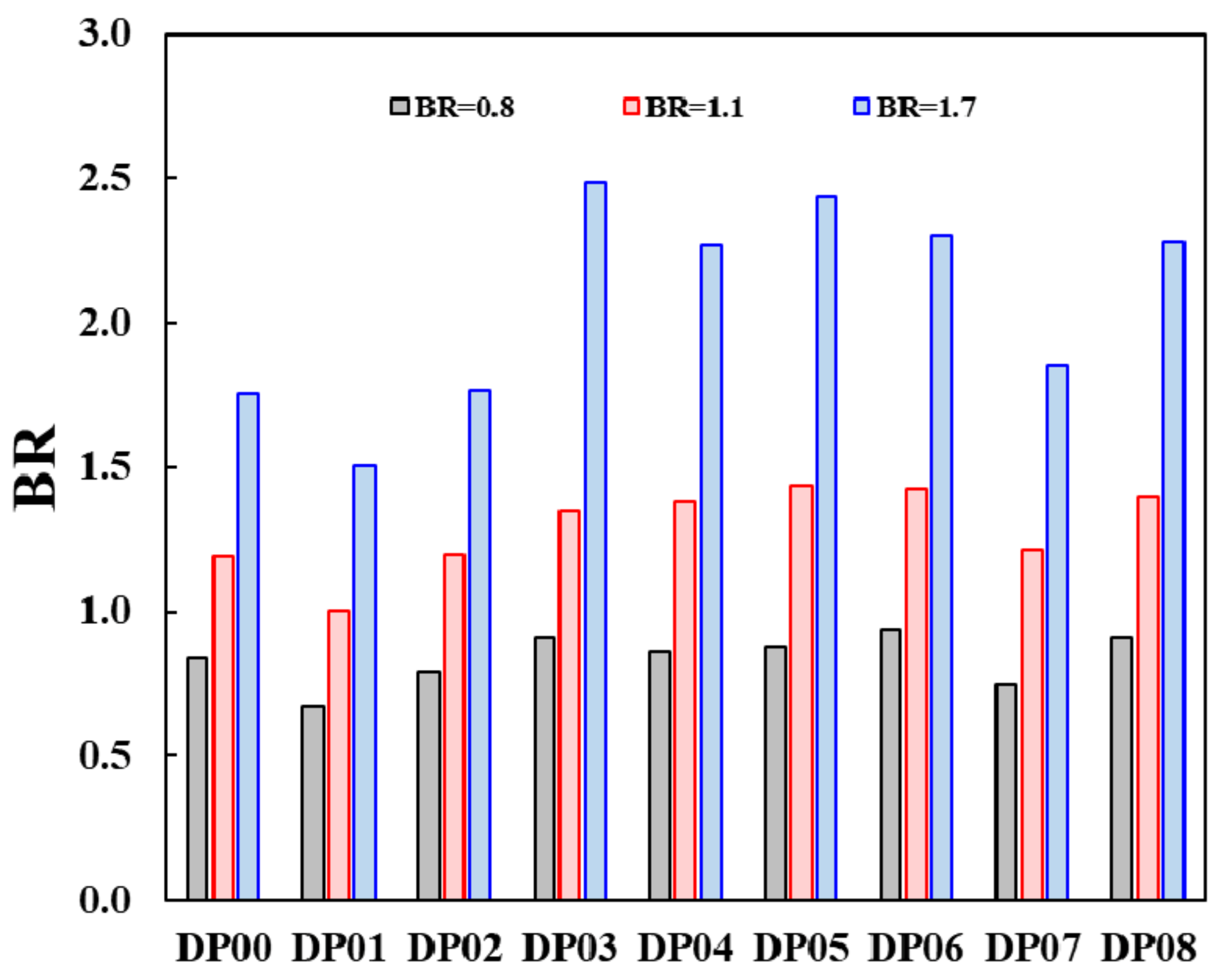
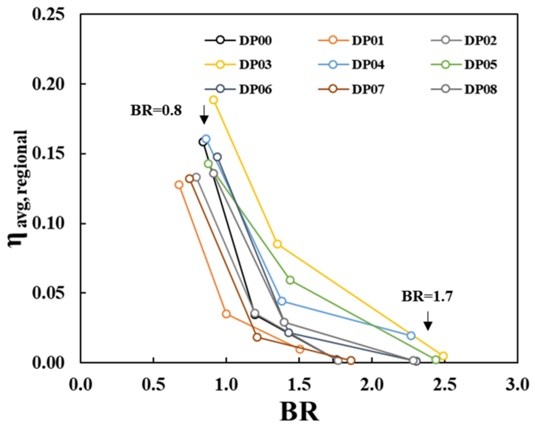
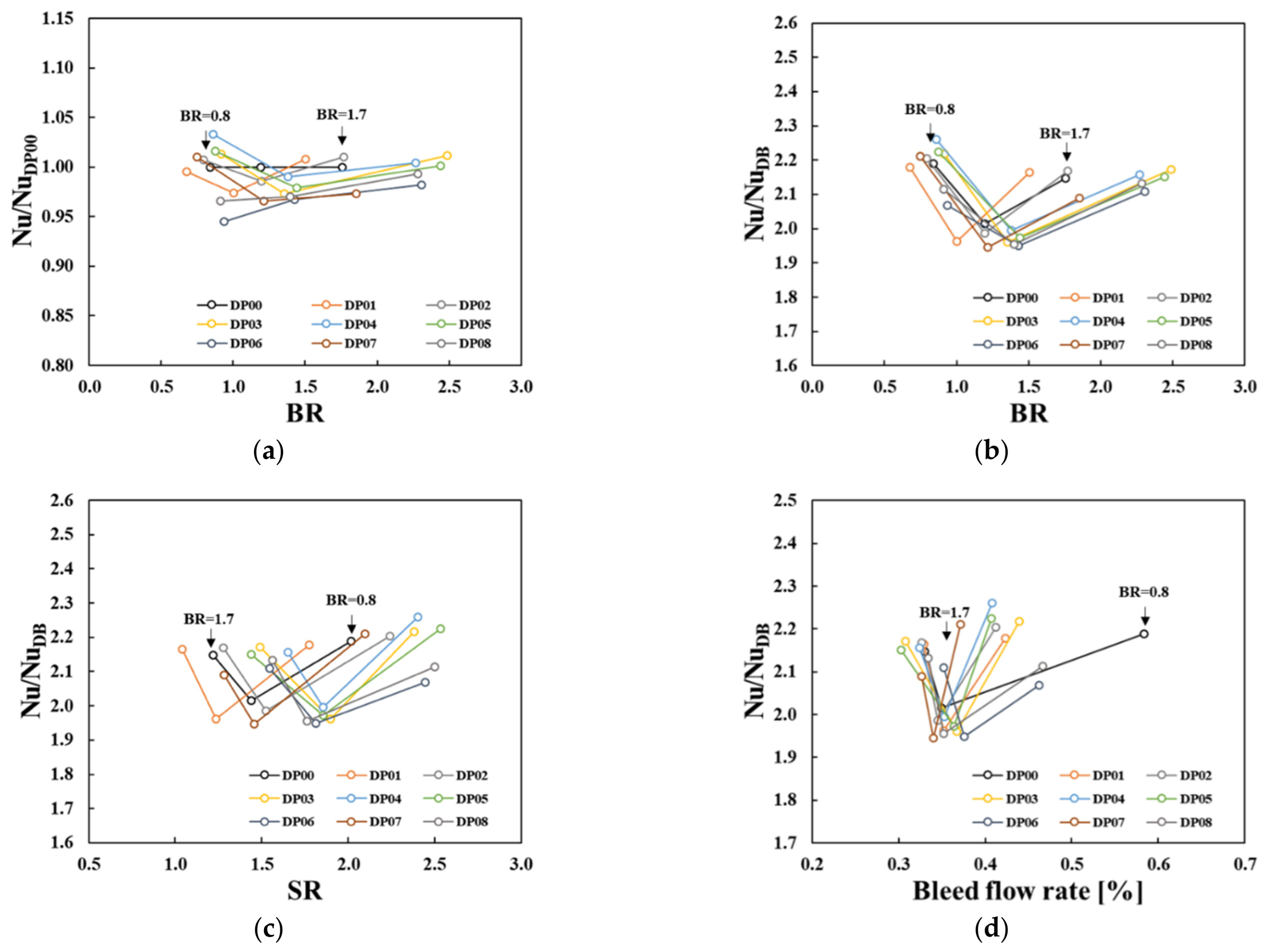
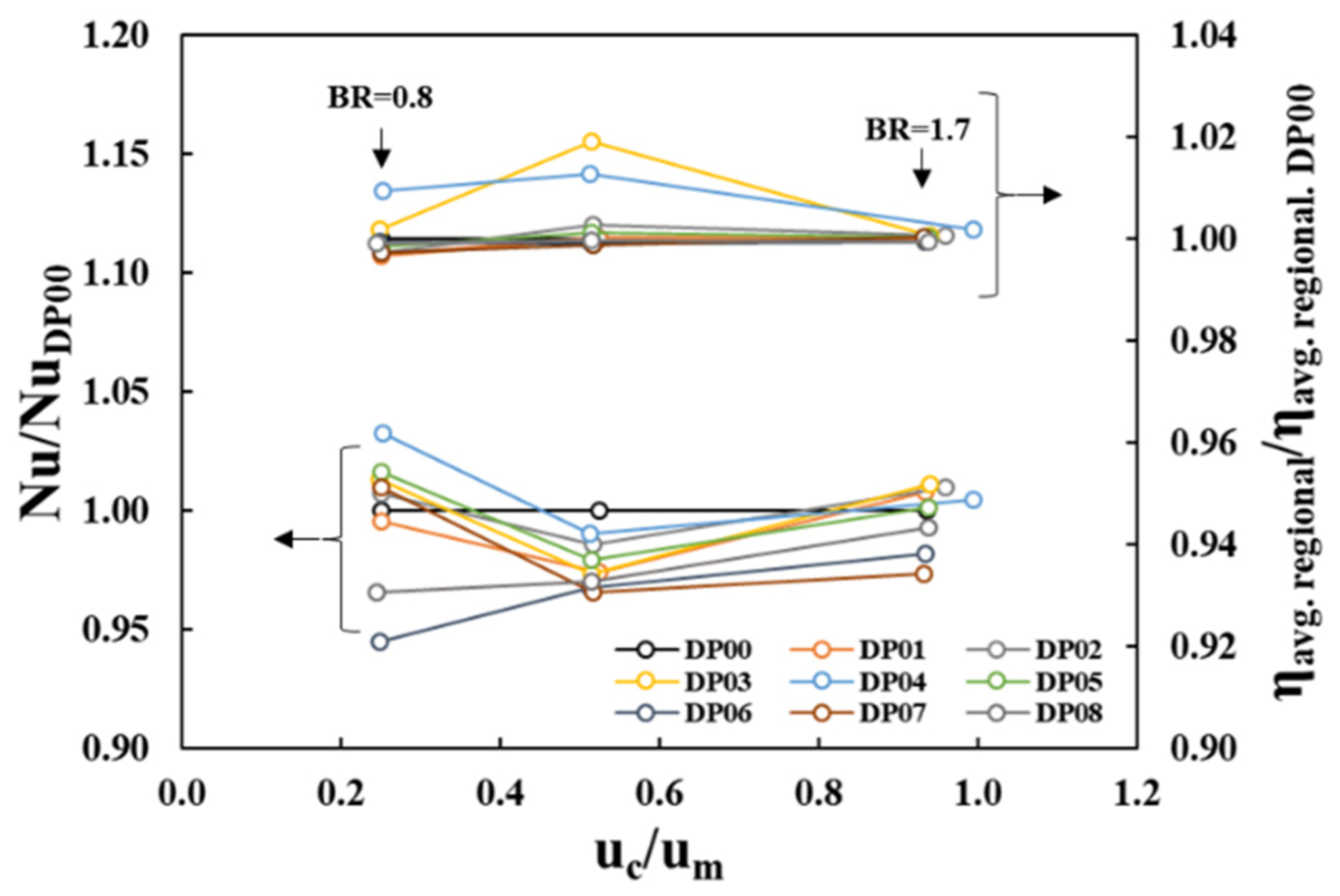
  • The heat transfer of a ribbed channel with film extraction is influenced by the position of the film hole. The comparison in blowing ratios among nine film hole positions showed maximum 19%, 30%, and 42% variations at BR = 0.8, 1.1 and 1.7, respectively;
  • Among the nine positions, the film holes located in the separated flow region (DP01, DP03, DP04 and DP05) showed better internal heat transfer performance compared to the reference position of DP00 for BR < 1.0 and BR > 1.5;
  • The film holes positioned close to the left-side wall (DP03, DP04 and DP05) performed better since they showed minimum reduction in internal heat transfer but still achieved enhancement in film effectiveness;
  • In a comparison of film effectiveness, DP03 showed the best performance. In addition, DP04 and DP05 demonstrated competitive performance, except at BR~1.5;
  • Overall, the films positioned at DP03 and DP04 showed a potential to achieve a net increase in internal and external heat transfer.
For future research, it is obvious that there is a need for more accurate flow field and heat transfer measurements on the combined configuration of internal and external heat transfer passage with the film hole for comprehensive understanding and validation of CFD modeling at all levels of fidelity.

Author Contributions

S.J. conducted analysis and drafted the paper. C.S. supervised the project and revised the paper. All authors have read and agreed to the published version of the manuscript.

Funding

The authors would like to recognize the financial support received from Virginia Tech in conducting the present research.

Acknowledgments

The authors would like to express special thanks to Brett Barker, Rolls-Royce Corporation for his guidance and engagement on outlining the research program.

Conflicts of Interest

The authors declare no conflict of interest.

References

  1. Walters, D.K.; Leylek, J.H. A Detailed Analysis of Film-Cooling Physics: Part I—Streamwise Injection With Cylindrical Holes. J. Turbomach. 1997, 122, 102–112. [Google Scholar] [CrossRef]
  2. Walters, D.K.; Leylek, J.H. A Systematic Computational Methodology Applied to a Three-Dimensional Film-Cooling Flowfield. J. Turbomach. 1997, 119, 777–785. [Google Scholar] [CrossRef]
  3. Leylek, J.H.; Zerkle, R.D. Discrete-Jet Film Cooling: A Comparison of Computational Results with Experiments. J. Turbomach. 1994, 116, 358–368. [Google Scholar] [CrossRef]
  4. Bergeles, G.; Gosman, A.D.; Launder, B.E. Near-Field Character of a Jet Discharged through a Wall at 30 Deg Toa Mainstream. AIAA J. 1977, 15, 499–504. [Google Scholar] [CrossRef]
  5. Bergeles, G.; Gosman, A.D.; Launder, B.E. The Near-Field Character of a Jet Discharged Normal to a Main Stream. J. Heat Transf. 1976, 98, 373–378. [Google Scholar] [CrossRef]
  6. Sinha, A.K.; Bogard, D.G.; Crawford, M.E. Film-Cooling Effectiveness Downstream of a Single Row of Holes with Variable Density Ratio. J. Turbomach. 1991, 113, 442–449. [Google Scholar] [CrossRef]
  7. Thurman, D.; Poinsatte, P. Experimental Heat Transfer and Bulk Air Temperature Measurements for a Multipass Internal Cooling Model with Ribs and Bleed. J. Turbomach. 2000, 123, 90–96. [Google Scholar] [CrossRef] [Green Version]
  8. Böttger, M.; Lange, M.; Mailach, R.; Vogeler, K. Experimental Study on the Influence of Film Cooling Hole Extraction on Heat Transfer and Flow Field in Internal Ribbed Cooling Channels of Turbine Blades. J. Turbomach. 2020, 142, 101005. [Google Scholar] [CrossRef]
  9. Böttger, M.; Lange, M.; Mailach, R.; Vogeler, K. Experimental Study on the Influence of the Streamwise Position of Film Hole Extraction in Internal Ribbed Cooling Channels of Turbine Blades. J. Glob. Power Propuls. Soc. 2019, 3, 580–591. [Google Scholar] [CrossRef]
  10. Klavetter, S.R.; McClintic, J.W.; Bogard, D.G.; Dees, J.E.; Laskowski, G.M.; Briggs, R. The Effect of Rib Turbulators on Film Cooling Effectiveness of Round Compound Angle Holes Fed by an Internal Cross-Flow. J. Turbomach. 2016, 138, 121006. [Google Scholar] [CrossRef]
  11. Liu, C.; Li, B.; Ye, L.; Zhu, H.; Zhang, C.; Song, W. Film Cooling Characteristics of Cross-Flow Coolant Passage with Various Relative Positions of Holes and Inclined Ribs. Int. J. Therm. Sci. 2021, 167, 106975. [Google Scholar] [CrossRef]
  12. Sakai, E.; Takahashi, T. Experimental and Numerical Study on Effects of Turbulence Promoters on Flat Plate Film Cooling. In Volume 5: Heat Transfer, Parts A and B; ASMEDC: Vancouver, BC, Canada, 2011; pp. 105–115. [Google Scholar] [CrossRef]
  13. Yavuzkurt, S.; Hassan, J.S. Evaluation of Two-Equation Models of Turbulence in Predicting Film Cooling Performance under High Free Stream Turbulence. In Volume 4: Turbo Expo 2007, Parts A and B; ASMEDC: Montreal, QC, Canada, 2007; pp. 259–268. [Google Scholar] [CrossRef]
  14. Charbonnier, D.; Ott, P.; Jonsson, M.; Cottier, F.; Kobke, T. Experimental and Numerical Study of the Thermal Performance of a Film Cooled Turbine Platform. In Volume 3: Heat Transfer, Parts A and B; ASMEDC: Orlando, FL, USA, 2009; pp. 1027–1038. [Google Scholar] [CrossRef]
  15. Ye, L.; Liu, C.; Zhu, H.; Luo, J. Experimental Investigation on Effect of Cross-Flow Reynolds Number on Film Cooling Effectiveness. AIAA J. 2019, 57, 4804–4818. [Google Scholar] [CrossRef]
  16. Walters, D.K.; Leylek, J.H.; Buck, F.A. Film Cooling on a Modern HP Turbine Blade: Part II—Compound-Angle Round Holes. In Proceedings of the ASME Turbo Expo 2002: Power for Land, Sea, and Air, Amsterdam, The Netherlands, 3–6 June 2002; Volume 3: Turbo Expo 2002, Parts A and B. pp. 1095–1101. [Google Scholar] [CrossRef]
  17. Xie, G.; Liu, X.; Yan, H. Film Cooling Performance and Flow Characteristics of Internal Cooling Channels with Continuous/Truncated Ribs. Int. J. Heat Mass Transf. 2017, 105, 67–75. [Google Scholar] [CrossRef]
  18. Kunze, M.; Vogeler, K. Flow Field Investigations on the Effect of Rib Placement in a Cooling Channel with Film-Cooling. J. Turbomach. 2014, 136, 031009. [Google Scholar] [CrossRef]
  19. Bogard, D.G.; Thole, K.A. Gas Turbine Film Cooling. J. Propuls. Power 2006, 22, 249–270. [Google Scholar] [CrossRef] [Green Version]
  20. Shen, J.R.; Wang, Z.; Ireland, P.T.; Jones, T.V.; Byerley, A.R. Heat Transfer Enhancement Within a Turbine Blade Cooling Passage Using Ribs and Combinations of Ribs With Film Cooling Holes. J. Turbomach. 1996, 118, 428–434. [Google Scholar] [CrossRef]
  21. Peet, Y.V.; Lele, S.K. Near Field of Film Cooling Jet Issued into a Flat Plate Boundary Layer: LES Study. In Volume 4: Heat Transfer, Parts A and B; ASMEDC: Berlin, Germany, 2008; pp. 409–418. [Google Scholar] [CrossRef] [Green Version]
  22. Tyagi, M.; Acharya, S. Large Eddy Simulation of Film Cooling Flow from an Inclined Cylindrical Jet. J. Turbomach. 2003, 125, 734–742. [Google Scholar] [CrossRef]
  23. Oliver, T.A.; Anderson, J.B.; Bogard, D.G.; Moser, R.D.; Laskowski, G. Implicit LES for Shaped-Hole Film Cooling Flow. In Volume 5A: Heat Transfer; American Society of Mechanical Engineers: Charlotte, NC, USA, 2017; p. V05AT12A005. [Google Scholar] [CrossRef]
  24. Kalghatgi, P.; Acharya, S. Modal Analysis of Inclined Film Cooling Jet Flow. J. Turbomach. 2014, 136, 081007. [Google Scholar] [CrossRef]
  25. Kawai, S.; Larsson, J. Dynamic Non-Equilibrium Wall-Modeling for Large Eddy Simulation at High Reynolds Numbers. Phys. Fluids 2013, 25, 015105. [Google Scholar] [CrossRef]
  26. Spalart, P.R. Young-Person’s Guide to Detached-Eddy Simulation Grids; NASA Langley Research Center: Hampton, VA, USA, 2001; p. 23. [Google Scholar]
  27. Yu, F.; Yavuzkurt, S. Near-Field Simulations of Film Cooling with a Modified DES Model. Inventions 2020, 5, 13. [Google Scholar] [CrossRef] [Green Version]
  28. Yu, F.; Yavuzkurt, S. Simulations of Film Cooling Flow Structure and Heat Transfer in the Near Field of Cooling Jets with a Modified DES Model. In ASME 2019 Heat Transfer Summer Conference; American Society of Mechanical Engineers: Bellevue, WA, USA, 2019; p. V001T05A004. [Google Scholar] [CrossRef]
  29. Burd, S.W.; Simon, T.W. Measurements of Discharge Coefficients in Film Cooling. J. Turbomach. 1999, 121, 243–248. [Google Scholar] [CrossRef]
  30. Liu, C.; Ye, L.; Zhu, H.; Luo, J. Investigation on the Effects of Rib Orientation Angle on the Film Cooling with Ribbed Cross-Flow Coolant Channel. Int. J. Heat Mass Transf. 2017, 115, 379–394. [Google Scholar] [CrossRef]
  31. Luo, J.; Liu, C.; Zhu, H. Numerical Investigation of Film Cooling Performance with Different Internal Flow Structures. In Volume 5B: Heat Transfer; American Society of Mechanical Engineers: Düsseldorf, Germany, 2014; p. V05BT13A008. [Google Scholar] [CrossRef]
  32. Han, J.C.; Zhang, Y.M.; Lee, C.P. Augmented Heat Transfer in Square Channels with Parallel, Crossed, and V-Shaped Angled Ribs. J. Heat Transf. 1991, 113, 590–596. [Google Scholar] [CrossRef]
  33. Park, J.S.; Han, J.C.; Huang, Y.; Ou, S.; Boyle, R.J. Heat Transfer Performance Comparisons of Five Different Rectangular Channels with Parallel Angled Ribs. Int. J. Heat Mass Transf. 1992, 35, 2891–2903. [Google Scholar] [CrossRef]
Figure 1. Geometry of an integrated ribbed internal cooling channel, film hole and external passage. Iso view (a) and front view (b).
Energies 14 04689 g001
Figure 2. Parametric definition of nine film hole locations in a ribbed channel.
Energies 14 04689 g002
Figure 3. Mesh for the computational domain (X8). Iso view (a), detailed view of film hole (b) and side view (c).
Energies 14 04689 g003
Figure 4. Geometry and computational domain for sensitivity study (Sinha et al. [6]).
Energies 14 04689 g004
Figure 5. Mesh for sensitivity study. Iso view (a), detailed view of film hole (b) and side view (c).
Energies 14 04689 g005
Figure 6. Distribution of dimensionless temperature and its difference (x-z view). Width = 3D (a) and width = 7D (b) and difference between the width of 3D and 7D (c).
Energies 14 04689 g006
Figure 7. Comparison of dimensionless temperature at the exit of the computational domain (z-y view, x/D = 30). Width = 3D (Mesh = Narrow X1) (a) and width = 7D (Mesh = 1X) (b).
Energies 14 04689 g007
Figure 8. Comparison of adiabatic effectiveness [6,27]. BR = 0.5, mesh and turbulence model sensitivity (a) and BR = 1.0, turbulence model sensitivity (b).
Energies 14 04689 g008
Figure 9. Adiabatic effectiveness and vorticity structure colored by dimensionless temperature, BR = 0.5. Fluent, X8, Realizable k-ε (a), Fluent, X8, SST (b) and CFX, X8, SST (c).
Energies 14 04689 g009
Figure 10. Adiabatic effectiveness and vorticity structure colored by dimensionless temperature, BR = 1.0. Fluent, X1, Realizable k-ε (a), Fluent, X1, SST (b) and CFX, X1, SST (c).
Energies 14 04689 g010
Figure 11. Convergence of mesh density, BR = 0.5, CFX. Average temperature on film hole exit (a) and averaged velocity of film hole inlet (b).
Energies 14 04689 g011
Figure 12. Variation in blowing ratio (BR).
Energies 14 04689 g012
Figure 13. Distribution of adiabatic effectiveness of film hole at DP01, DP00 and DP02, CFX (x-z view).
Energies 14 04689 g013
Figure 14. Distribution of adiabatic effectiveness of film hole at DP07, DP06 and DP08, CFX (x-z view).
Energies 14 04689 g014
Figure 15. Distribution of adiabatic effectiveness of film hole at DP04, DP03 and DP05, CFX (x-z view).
Energies 14 04689 g015
Figure 16. Data processing for laterally averaged film effectiveness (red-colored lines).
Energies 14 04689 g016
Figure 17. Laterally averaged adiabatic effectiveness. BR = 0.8 (a), BR = 1.1 (b) and BR = 1.7 (c).
Energies 14 04689 g017
Figure 18. Distribution of adiabatic effectiveness of film hole at DP04, DP03 and DP05, Fluent (x-z view).
Energies 14 04689 g018
Figure 19. Laterally averaged adiabatic effectiveness, Fluent.
Energies 14 04689 g019
Figure 20. 3D Vortex structure and dimensionless temperature contours overlaid with velocity vector at various streamwise locations (x/D = 0.5~15), CFX. 3D vortex structure through film hole (a), x/D = 0.5 (b), x/D = 1 (c), x/D = 5 (d), x/D = 10 (e) and x/D = 15 (f).
Energies 14 04689 g020
Figure 21. Regional-averaged adiabatic effectiveness.
Energies 14 04689 g021
Figure 22. Comparison of discharge coefficients [30,31].
Energies 14 04689 g022
Figure 23. Distribution of normalized Nusselt number (Nu/NuDB) in the 7th rib segment, BR = 0.8, CFX (z-x view).
Energies 14 04689 g023
Figure 24. Comparison of normalized Nusselt number (Nu/NuDB) in the 7th rib segment, DP00 (z-x view).
Energies 14 04689 g024
Figure 25. Comparison of normalized average Nusselt number based on blowing ratio, suction ratio and bleed flow ratio. Nu/NuDP00 vs. BR (a), Nu/NuDB vs. BR (b), Nu/NuDB vs. SR (c) and Nu/NuDB vs. Bleed flow rate (d).
Energies 14 04689 g025
Figure 26. Comparison of normalized average Nusselt number based on Reynolds number of ribbed channels [8,32,33].
Energies 14 04689 g026
Figure 27. Comparison of normalized average Nusselt number and regional averaged adiabatic effectiveness.
Energies 14 04689 g027
Table 1. Geometric parameters of the film hole and ribbed channel.
Geometrical ParametersSymbolValue
Passage aspect ratioH/W1
Rib angleα45°
Rib height to width ratioh/e1
Rib pitch to height ratiop/h10
Hole diameterD5 mm
Ratio of film hole diameter to rib heightD/h0.38
Ratio of film hole vertical height to hole diameterl/D1
Film hole inclination angle, lateral to mainstream flow directionβ30°
Film hole inclination angle, in mainstream flow direction (compound angle)γ90°
Table 2. Summary of boundary conditions.
BR = 0.8,
DR = 1.6
BR = 1.1,
DR = 1.6
BR = 1.7,
DR = 1.6
Cooling flowInletTotal pressure101,565 Pa102,040 Pa103,515 Pa
Total temperature153.00 K
OutletStatic pressure101,405 Pa
WallTemperature283.15 K
Mainstream flowInletTotal pressure101,555 Pa
Total temperature302.00 K
OutletStatic pressure101,315 Pa
WallAdiabatic-
Table 3. Meshes generated for sensitivity study.
Width NodesElements
Narrow (3D)Narrow X16.1M5.6M
Wide (7D)X15.8M5.7M
X212.7M12.5M
X425.2M24.9M
X850.7M50.1M
X1678.3M77.7M
Publisher’s Note: MDPI stays neutral with regard to jurisdictional claims in published maps and institutional affiliations.

