Article

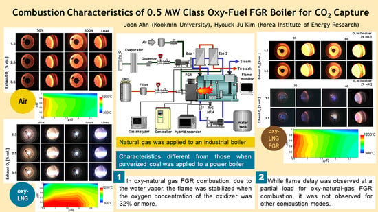
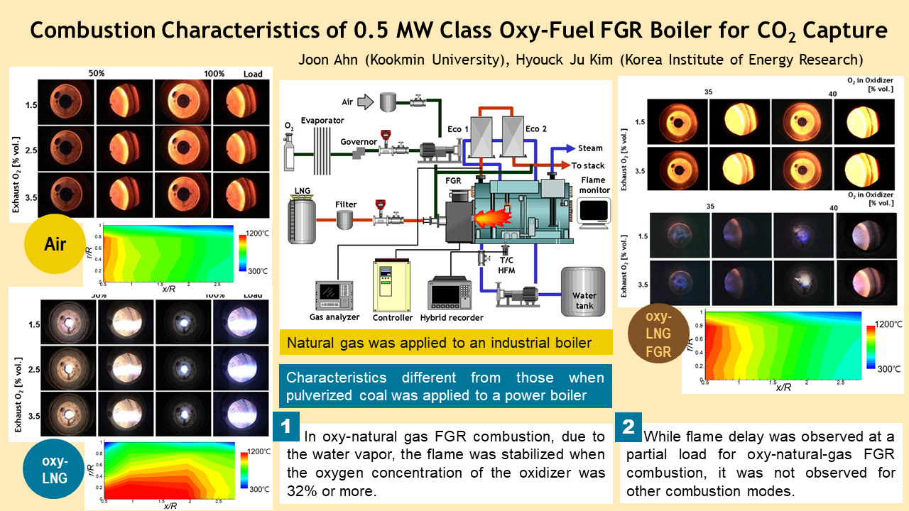
Combustion Characteristics of 0.5 MW Class Oxy-Fuel FGR (Flue Gas Recirculation) Boiler for CO2 Capture

1
School of Mechanical Engineering, Kookmin University, Seoul 02707, Korea
2
Korea Institute of Energy Research, Daejeon 34129, Korea
*
Author to whom correspondence should be addressed.
Energies 2021, 14(14), 4333; https://doi.org/10.3390/en14144333
Submission received: 3 June 2021 / Revised: 12 July 2021 / Accepted: 16 July 2021 / Published: 18 July 2021
(This article belongs to the Special Issue CO2 Based Energy Harvesting and Storage Systems)

Abstract

:
A 0.5 MW class oxy-fuel boiler was developed to capture CO2 from exhaust gas. We adopted natural gas as the fuel for industrial boilers and identified characteristics different from those of pulverized coal, which has been studied for power plants. We also examined oxy-fuel combustion without flue gas recirculation (FGR), which is not commonly adopted in power plant boilers. Oxy-fuel combustion involves a stretched flame that uniformly heats the combustion chamber. In oxy-natural-gas FGR combustion, water vapor was included in the recirculated gas and the flame was stabilized when the oxygen concentration of the oxidizer was 32% or more. While flame delay was observed at a partial load for oxy-natural-gas FGR combustion, it was not observed for other combustion modes. In oxy-fuel combustion, the flow rate and flame fullness decrease but, except for the upstream region, the temperature near the wall is distributed not lower than that for air combustion because of the effect of gas radiation. For this combustion, while the heat flux is lower than other modes in the upstream region, it is more than 60% larger in the downstream region. When oxy-fuel and FGR combustion were employed in industrial boilers, more than 90% of CO2 was obtained, enabling capture, sequestration, and boiler performance while satisfying exhaust gas regulations.

Graphical Abstract

1. Introduction

Increasing atmospheric CO2 emissions from burning fossil fuels are a major barrier to greenhouse gas reduction and global warming control. While the use of renewable and clean energy sources such as solar and wind energy has increased considerably over the past decades, owing to the enormous increase in global energy demand, fossil fuels will continue to be used for decades to come. The use of fossil fuels warrants the incorporation of carbon capture and sequestration (CCS) technologies—which include oxy-fuel combustion and pre- and postcombustion carbon capture technologies—into power plants. Oxy-fuel combustion technology is one of the most promising carbon capture technologies because it allows minor modifications to be made to existing or new power plants [1,2].
Oxy-fuel combustion is the process of burning fuel in an atmosphere of pure oxygen or a mixture of oxygen and fuel gases instead of air. The process generates exhaust gas with a high CO2 concentration, facilitating CO2 capture after the condensation of water vapor [3]. The captured CO2 is used as industrial raw material or sequestered. Recently, sequestration techniques including underground injection are being actively studied [4,5]. A review of the use of oxy-fuel combustion in existing combustion systems (including gas turbines and boilers) and in new oxygen transport reactors is presented in [1].
Before the use of oxy-fuel combustion in existing combustion systems, the following differences should be examined. First, the mass flow rate of the combustion gas can be reduced by about 75%, which would decrease the heat loss and equipment volume [6]. However, since the heat transfer characteristics of the combustion chamber and heat exchanger are different, a system that recycles CO2 present in the exhaust gas has been frequently attempted. Second, since considerable energy is required for separating oxygen from air, up to 15% of energy can be used for coal-fired power generation [7]. The use of chemical looping technology for reducing this energy is being studied. Furthermore, condensation easily occurs; therefore, CO2 can be separated, or the heat of condensation can be utilized [8,9].
The use of oxy-fuel combustion with pulverized coal and in circulating-fluidized-bed coal-fired power plants and gas-turbine-based power plants has been studied [9]. In Korea, coal and gas account for 36.8% and 31.8% of electricity generation, respectively [10]; therefore, great effects are expected when CCS are performed. In Korea, CO2 emissions from fuel combustion in the industrial sector account for about 40% of the total CO2 emissions, excluding indirect emissions from electricity consumption. According to manufacturing energy consumption data, boilers account for the largest share of CO2 emissions at 8.8% [11]; therefore, using oxy-fuel combustion in industrial boilers is expected to significantly reduce greenhouse gas emissions.
In this study, as shown in Figure 1, an industrial boiler that could obtain high-concentration CO2 through oxy-fuel combustion was constructed. In a 50-kW furnace-type boiler, a small-scale model experiment was performed in the manner described in previous studies [12,13]. When oxy-fuel combustion was used, the boiler combustion chamber could be properly heated even with a small flow rate through gas radiation. However, for long-term operation with oxy-fuel combustion and high flame temperature, the burner should be properly protected. Analysis of the exhaust gas revealed that maintaining the airtightness of the system was crucial to achieve a high concentration of CO2 or low nitrogen oxides (NOx) [13].
In this study, the oxy-fuel boiler was scaled up to 0.5 MW. On the basis of the results of previous studies [12,13], the gas tightness of the system was improved and CO2 recirculation, which was not considered in previous studies, was included. A furnace flame tube-type boiler, which is more widely used compared with the furnace type in [12,13], was used. An economizer was installed at the outlet to test the heat transfer characteristics of the flame tube and economizer together. The thermodynamic optimization of the system considering the heat recovery [14] and the heat transfer characteristics of individual components are also very important, but the discussion in this paper is limited to combustion and heat transfer in the combustion chamber. When oxy-fuel combustion is used in large-volume boilers, measures are required to stretch the flame and protect the burner from high-temperature flames. In this study, a coaxial burner was fabricated for both oxy-fuel air combustion and oxy-fuel FGR combustion (Figure 2), and the volume of the flame was secured to achieve an even temperature distribution inside the boiler. The burner is detailed in Section 2.1.
In this study, a 0.5 MW class industrial boiler system employing oxy-fuel combustion was constructed. Previous research on oxy-fuel boilers has been focused on boilers for coal-fired power generation [9]. Studies on natural gas industrial boilers have been very rare, except for the authors’ previous studies [12,13,15]. Unlike coal, natural gas generates a large amount of water vapor in the combustion process; therefore, its combustion and heat transfer characteristics are different. In this study, the temperature distribution inside a combustion chamber and the heat flux on the wall of the combustion chamber were measured; experimental data on the temperature distribution in a combustion chamber are more scarce compared with flame image data.
In particular, this study examined FGR (flue gas recirculation) combustion, which was not investigated in a previous study [13]. When the combustion gas—liquefied natural gas (LNG)—is recycled, a considerable amount of water vapor enters the combustion system, and the combustion characteristics change. This study investigated the change in combustion characteristics. Furthermore, since the water vapor contained in the combustion gas changes the gas radiation characteristics, the detailed temperature distribution in the combustion chamber and the heat flux on the wall were measured and examined. Finally, while most of the NOx in coal is fuel NOx, in natural gas, most of it is infiltrated thermal NOx, which was analyzed in this study.

2. Experimental Setup and Methods

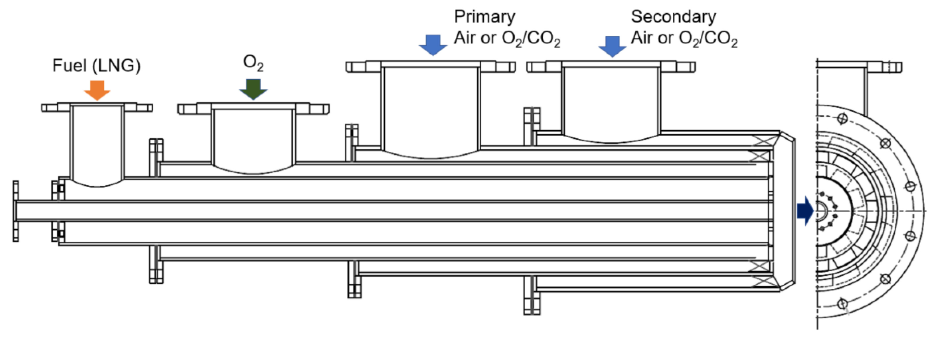
2.1. Oxy-Fuel, Air, and FGR Convertible Burner

In this study, a 0.5 MW class oxy-fuel, air, and FGR convertible burner was designed by referring to the authors’ previous studies [12,13,15] and the concepts of oxy-fuel burners found in open literature. The position of the nozzle in a 50-kW burner was moved in the axial direction to cope with the combustion mode [12,13], and the 0.5-MW burner was used to control the supply passage of the oxidizer to support FGR. Among the oxy-fuel FGR boiler designs for power generation found in open literature, burners for pulverized coal (PC) have been mainly referred to.
While oxy-PC burners of the coaxial (Air Liquide [16], Alstom Power [17]), eccentric duct (Hitachi [18]), and tangential (Doosan Babcock [19]) types have been used as an air and oxy-fuel FGR convertible burner, the coaxial type has been the most widely used [9]. In this study, a coaxial-type burner was designed to examine the oxy-fuel operation mode without recirculation.
As shown in Figure 2, natural gas was used as the fuel, and it was supplied to the central axis and oxidizer through triple coaxial–annular spaces. Valves and dampers were installed in the triple annular spaces to respond to the combustion mode. In the case of an oxy-fuel flame, flame holding is better than air combustion [20,21]; hence, oxygen was supplied through a nozzle to produce a jet flame. The jet flame can effectively heat the furnace as it extends in the axial direction [22].
For air and recirculation combustion, the oxidizer was divided into double swirlers and supplied to control according to combustion conditions. When the swirler is used, a recirculation zone is created at the center and radial jet flow occurs, stabilizing the flame in air and recirculation combustion [23,24]. Furthermore, even if the type of fuel or combustion mode is changed, a similar type of flame can be obtained, and stabilization and flame length can be controlled by adjusting the momentum ratio of the primary and secondary flows [25].

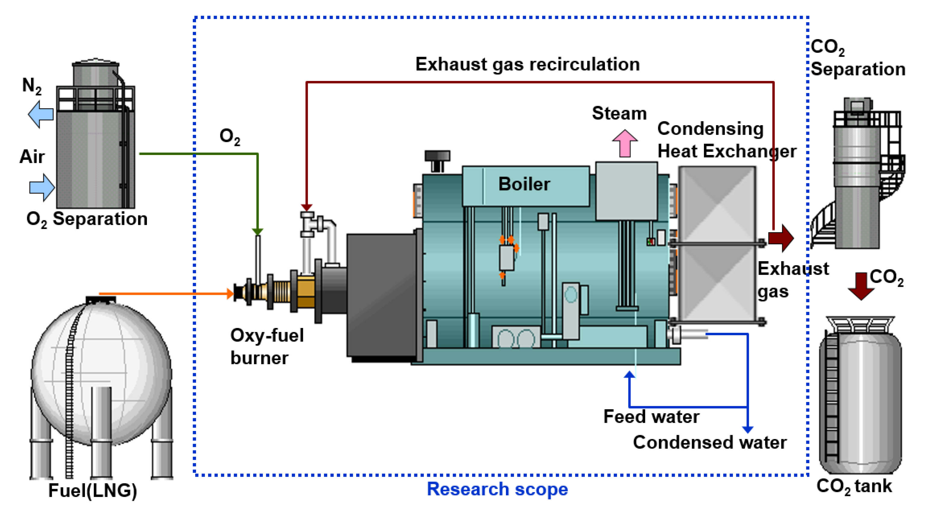
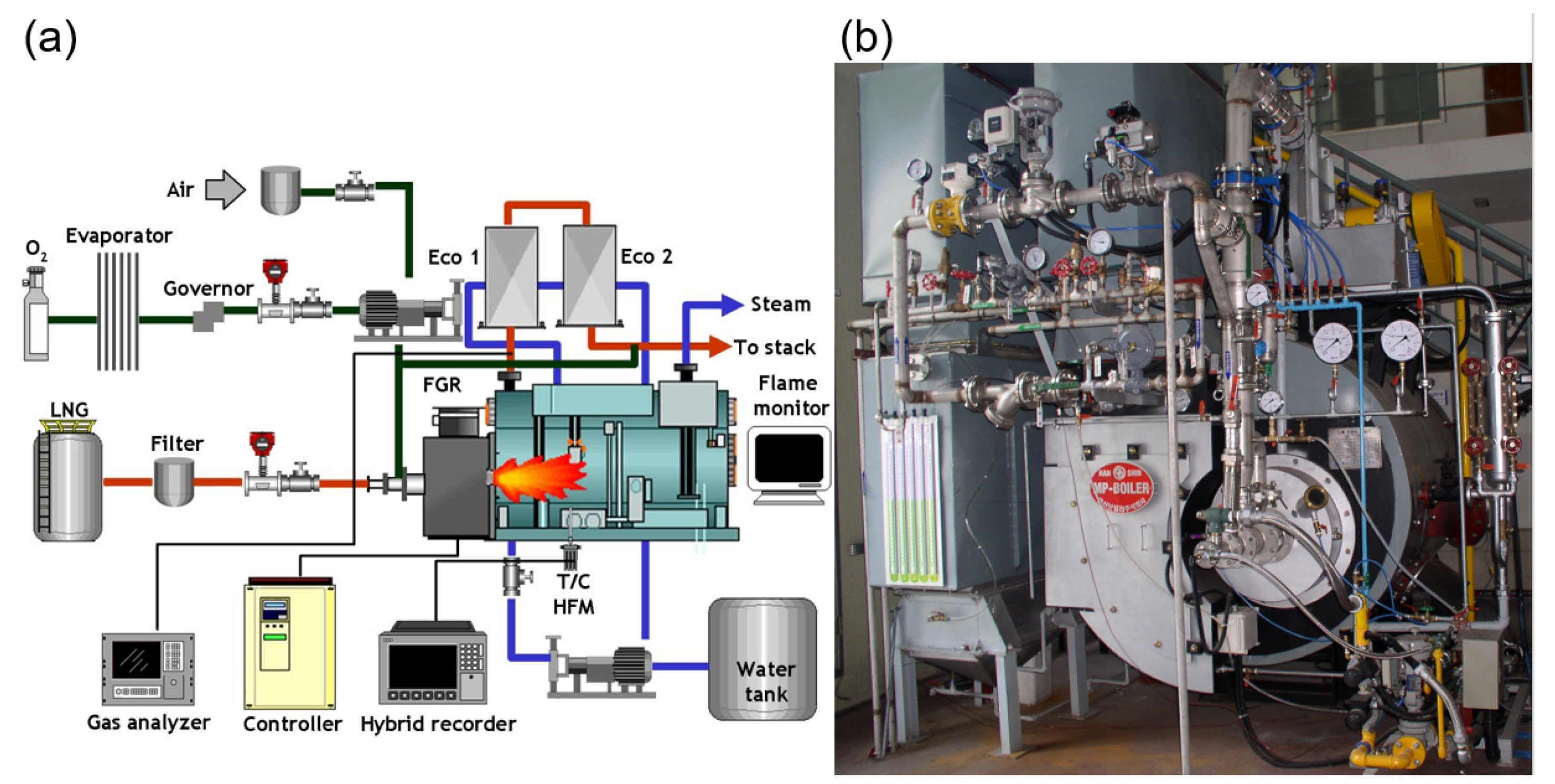
2.2. Oxy-Fuel Boiler and Instrumentation

As shown in Figure 3, the experimental setup was designed to obtain a high concentration of CO2 when oxy-fuel combustion was used in an industrial boiler. The boiler used was a 0.5 MW class furnace tube boiler, and FGR and a condensing heat exchanger were not covered in the 50-kW class model test [12,13].
The fuel was natural gas and supplied through a filter, as shown in Figure 3, to the combustor at a flow rate of 40 N m3/h at a load of 100%. Oxygen was supplied through an evaporator, and it exchanged heat with the exhaust gas during oxy-fuel and FGR combustion. In FGR, a large amount of water vapor is contained in the recycled gas, which affects the combustion stability. The flame was stabilized when the oxygen concentration of the oxidizer was 32% or more.
In this study, an oxidizer was supplied; therefore, the dry-based oxygen concentration was 35% and 40% for FGR. The recirculation rate was defined as the flow rate ratio of the fuel and CO2 contained in the recirculation gas (Equation (1)).
Recirculation   rate = volume   flow   rate   of   CO 2   in   the   recirculation   gas volue   flow   rate   of   fuel   ( natural   gas )
The recirculation rate defined in this way is 3.4~3.5 at 35% oxidizer O2 and 2.7~2.8 at 40% oxidizer O2 depending on the oxygen concentration of the exhaust gas.
In oxy-fuel combustion, the flow rate of oxygen was controlled by an electromagnetic valve with a mass flow controller. In air combustion, the flow rate of air was adjusted by controlling the rotation speed of the blower inverter while monitoring the oxygen concentration of the exhaust gas. In FGR combustion, the flow rate of the recycle gas was also controlled by an inverter to match the oxygen concentration of the oxidizer.
In the furnace tube boiler, heat is primarily transferred directly from the combustion chamber, and the exhaust gas transfers heat through a two-pass structure. In the combustion chamber, a 150 mm-diameter quartz observation window was installed to observe the flames from the front and sides. A camcorder (SONY TRV-30) was installed in front of the observation window to obtain flame images.
The temperature inside the combustion chamber was measured to observe the effect of the high-temperature oxy-fuel flame on the heat transfer characteristics of recirculation. R-type thermocouples, which can measure temperatures up to 1450 °C, were installed in the combustion chamber. The tolerance was ±2.5 °C at a temperature of 1000 °C. As shown in Figure 3b, a thermocouple was installed at the central axis of the cylinder-shaped combustion chamber, and the temperature was measured while moving from the central axis to the wall to obtain the temperature distribution inside the combustion chamber.
In oxy-fuel combustion, gas radiation is important because the exhaust gas comprises CO2 and water vapor, which cause gas radiation. To verify this, the heat flux distribution on the wall of the combustion chamber was measured using a heat flux sensor (Vatell, HFM-6D/H) that could obtain both convective and radiant heat flux by directly measuring the temperature gradient on the wall.
Gas was collected at the boiler outlet and its components were analyzed with a gas analyzer. Among the exhaust gas components, CO2, O2, CO, and NO were analyzed, and two Siemens Ultramat 23 and one Oxymat 61 were used. The CO2, CO, and NO measured by Ultramat 23 were calibrated before and after the experiment on the basis of a standard gas with an accredited certificate. O2 measured with Oxymat 61 was calibrated using high-purity air at intervals of 3 h. For determining the concentration of the exhaust gas component, after setting the combustion conditions, a stabilization time of 10 min or more was secured and the average value of the measurement result over 3 min was obtained. The uncertainties listed in the test certificate were ±0.2% for the O2 and CO2 components, and the maximum uncertainties for the CO and NO concentrations were estimated to be 7.6 and 7.3 ppm, respectively, for the measuring span adopted in the present experiment.

3. Results and Discussion
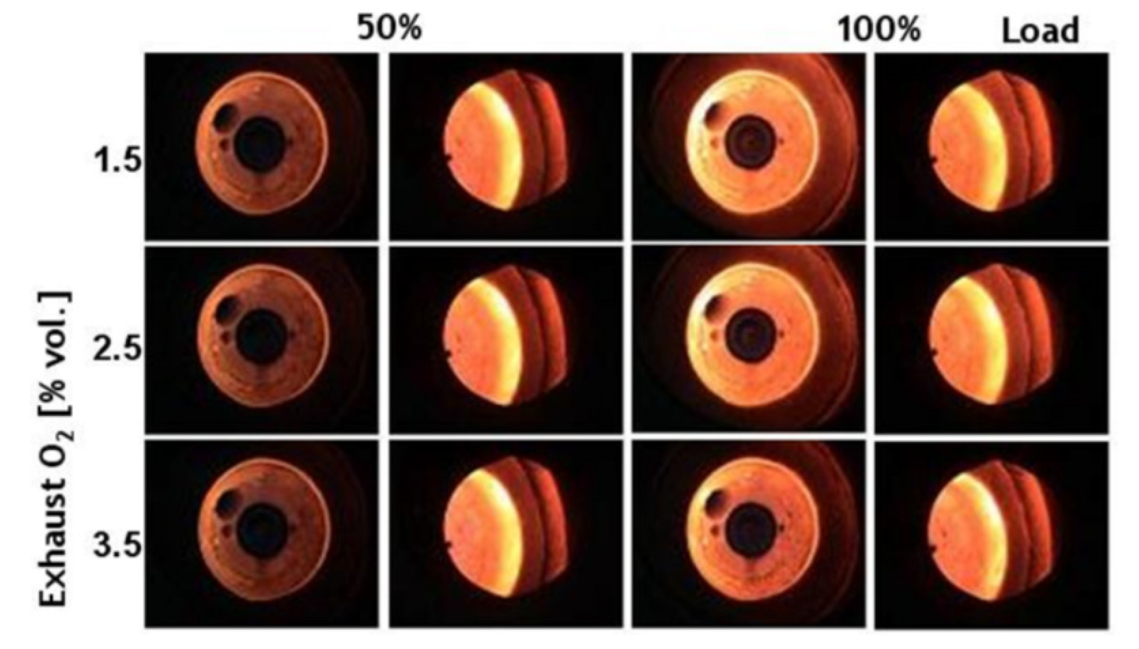
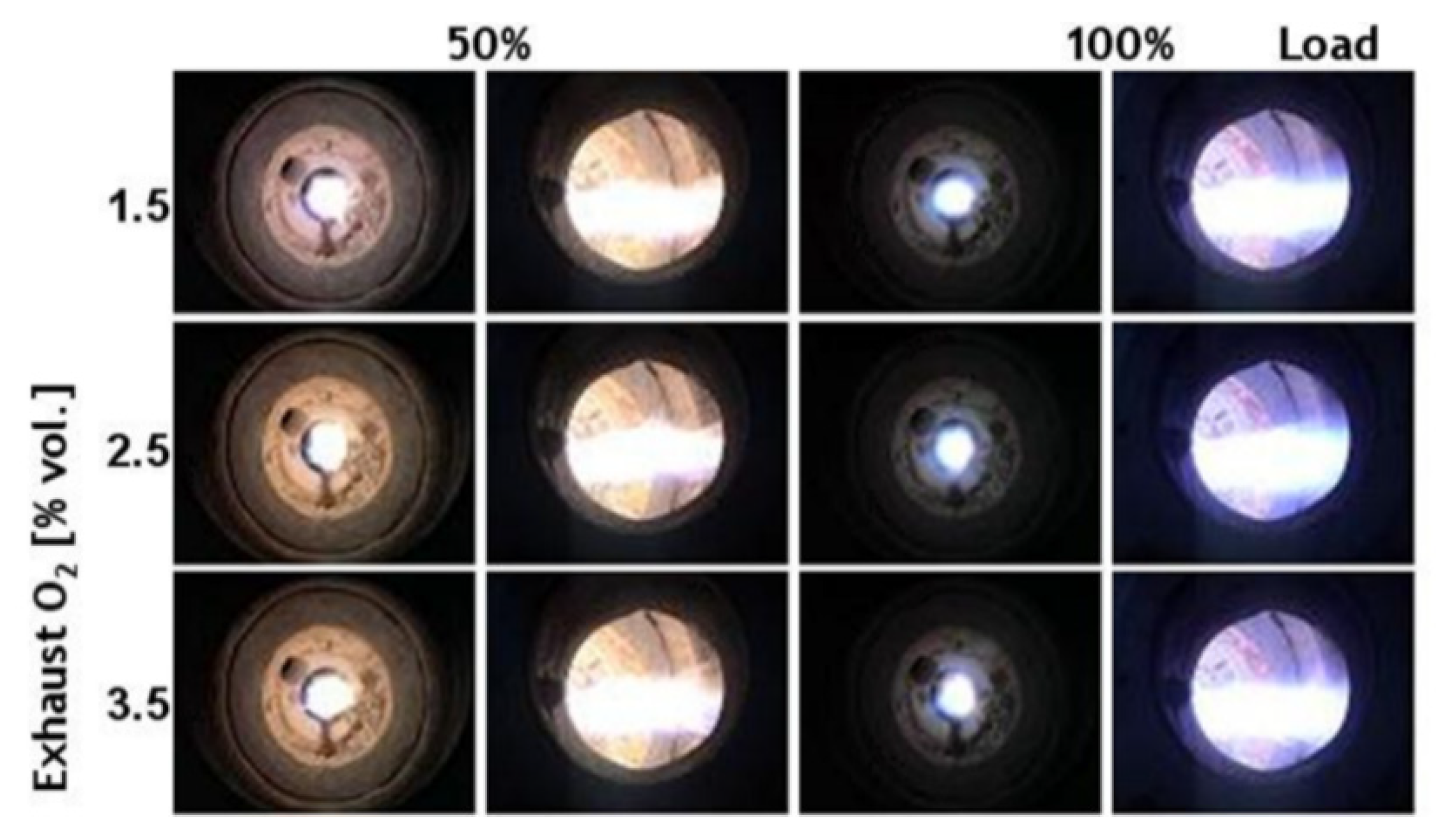
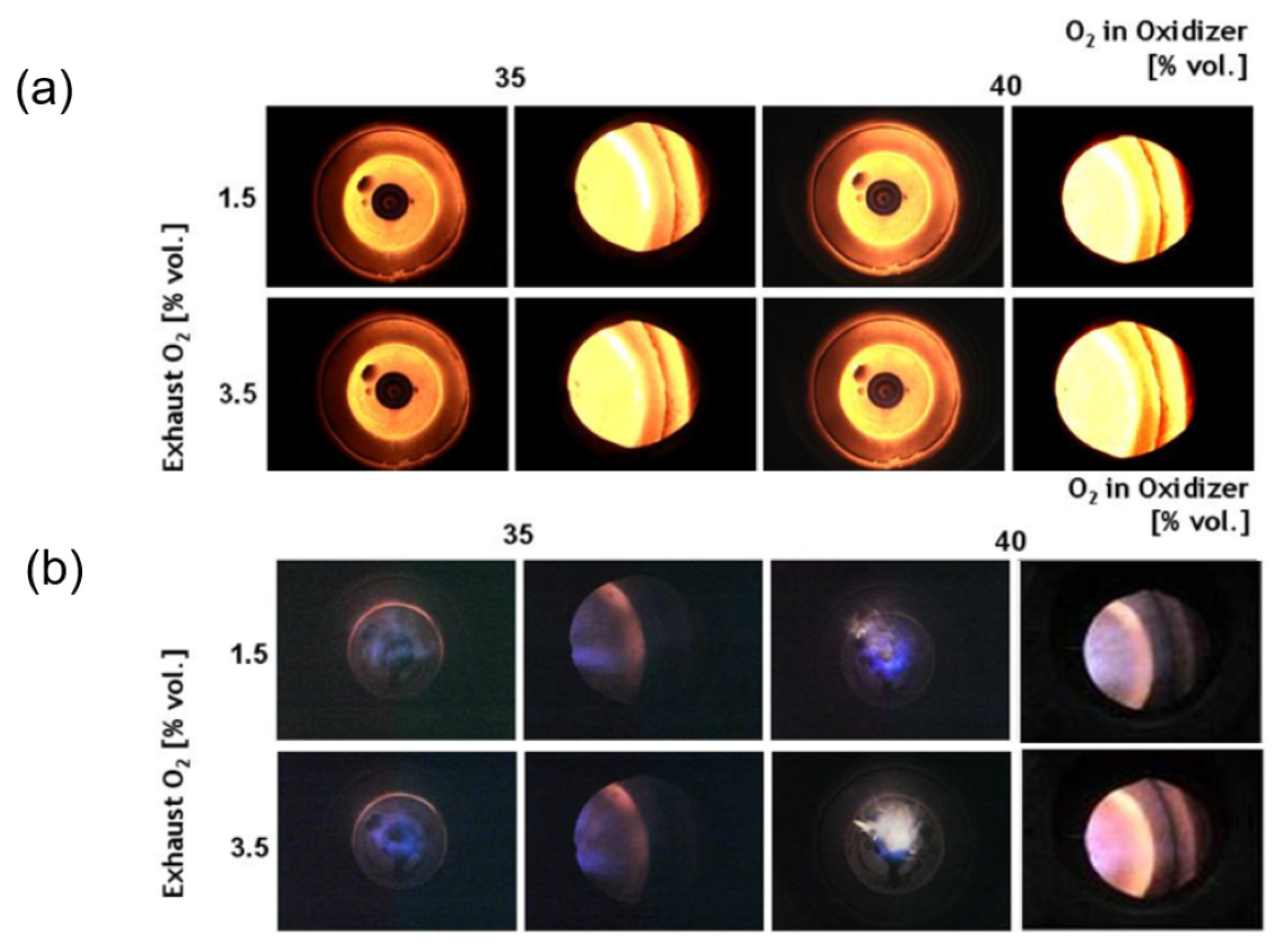
3.1. Flame

In air combustion, as in the case of previous studies [23,24] that used a swirler, a recirculation area was created, and the flame spread in the radial direction and was held near the burner. In the side image of the flame (Figure 4), the flame is located near the burner; in the front image, the burner tile is glowing. Comparing 50% and 100% loads, the luminance of the flame is high and the castable refractory is glowing brighter under the larger combustion load (100%). In air combustion, the change in the flame with the air ratio is not large in the exhaust gas oxygen concentration range of 1.5% to 3.5%. Consequently, air ratio and operating load can be determined by energy efficiency or emission control.
In oxy-fuel combustion, oxygen is injected through a nozzle to extend the flame in the flow direction (Figure 5). From the side images in Figure 5, the flame extending in the flow direction can be clearly observed. At both 50% and 100% loads, the characteristics of oxy-fuel flames [21,22] appear, in which the volume of the flame decreases and the luminance increases compared with air combustion. The burner tile’s glowing was significantly reduced compared with the air combustion in Figure 4. The light from the burner tile is observed more clearly as the flow direction momentum decreases at 50% of the load. Similar to air combustion, the change in the flame resulting from excess oxygen is not distinct.
In oxy-fuel FGR, when the dry-based oxygen concentration of the oxidizer was lowered to the air level of 21%, it contained considerable moisture and did not generate a flame. As a result of the experiment in which the recirculation rate was varied, a stable flame was obtained when the oxygen concentration of the oxidizer was 32% or more. This issue did not appear in oxy-PC and was only observed for natural gas. Flame images obtained for 35% and 40% oxygen for the FGR oxidizer are compared in Figure 6.
At 100% load (Figure 6a), the flame is close to the burner and the refractory is heated, similar to the case of air combustion shown in Figure 4. There is no significant change in the flame in the range of 1.5% to 3.5% of the flue gas oxygen. Comparing the flame to the recirculation rate shows that the refractory glows brighter in the case of an oxygen concentration of 40%. This appears to be because the propagation speed and temperature of the flame increased with the oxygen concentration.
Air combustion and oxy-natural-gas FGR are similar at full load but very different at partial load (see Figure 4). At 50% load (Figure 6b), the momentum of the oxidizer decreased and the flame was elongated in the flow direction. Moreover, the refractory was weakly reddish compared with the case of 100% load. It can also be interpreted as the occurrence of flame delay when compared to air combustion with the same load. The flame was blue because the fuel—natural gas—was mainly methane. At 50% load, unlike air combustion, the burner tile glowed weakly and was ring shaped.
When the recirculation rate was decreased to oxygen in the FGR gas of 40%, the tangential momentum decreased and the flame appeared downstream, with the end of the flame being white, as in the case of oxy-fuel combustion (see Figure 5). This phenomenon is more evident in the flue-gas oxygen of 3.5%. Unlike other combustion modes, in oxy-natural-gas FGR, the flame shape varies greatly depending on the combustion load and excess oxygen.

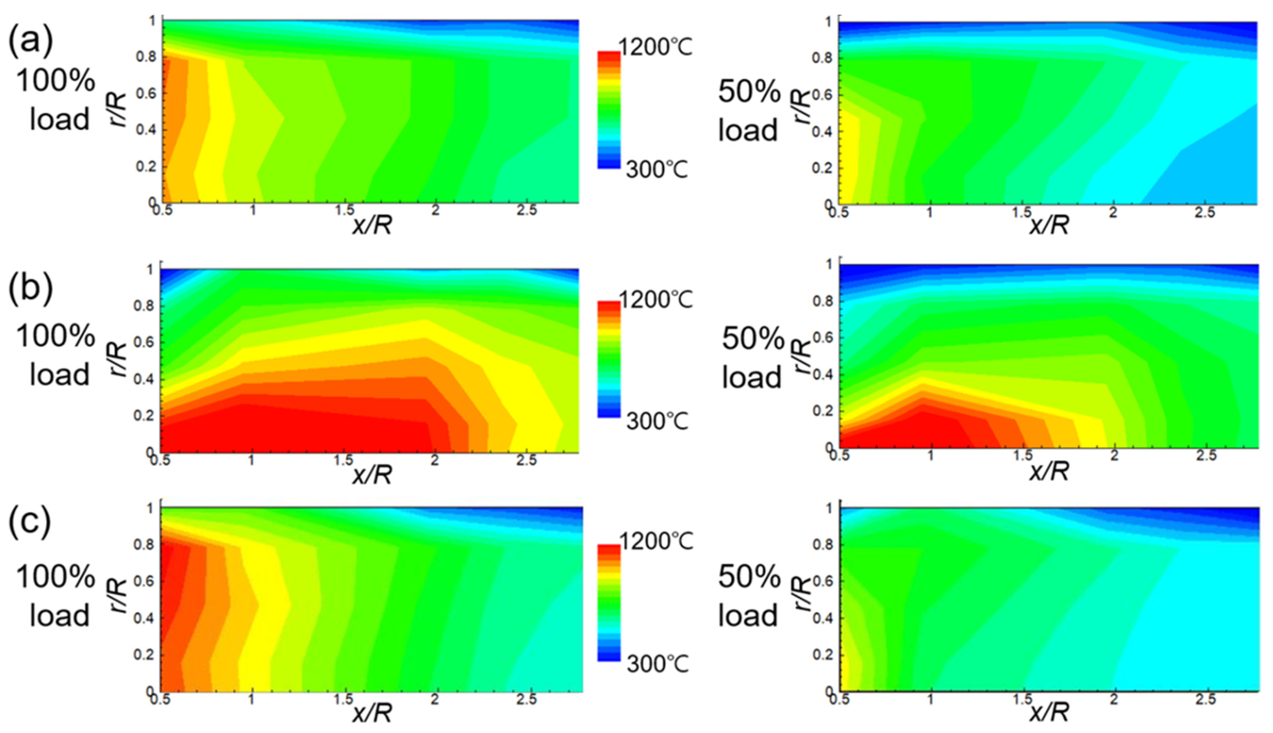
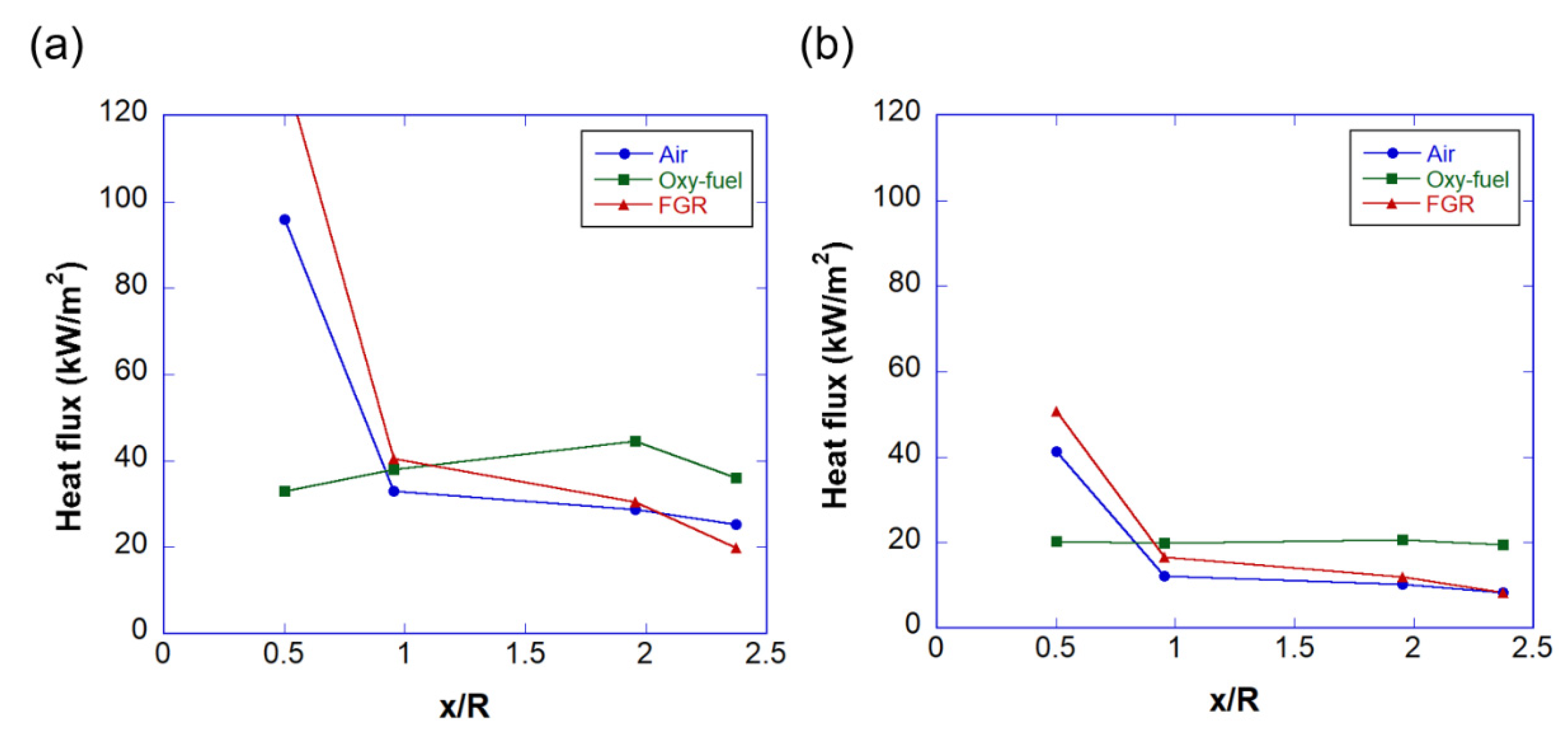
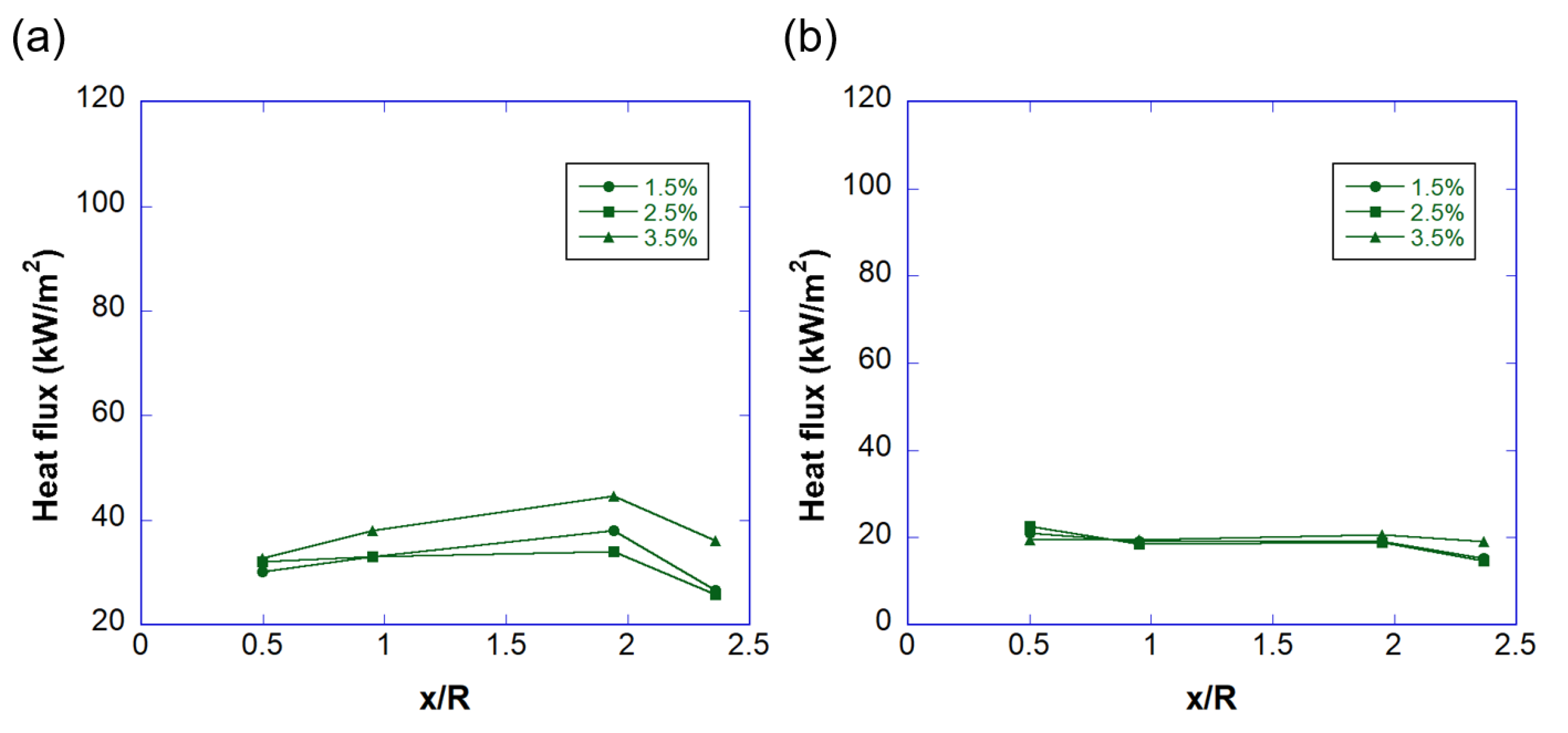
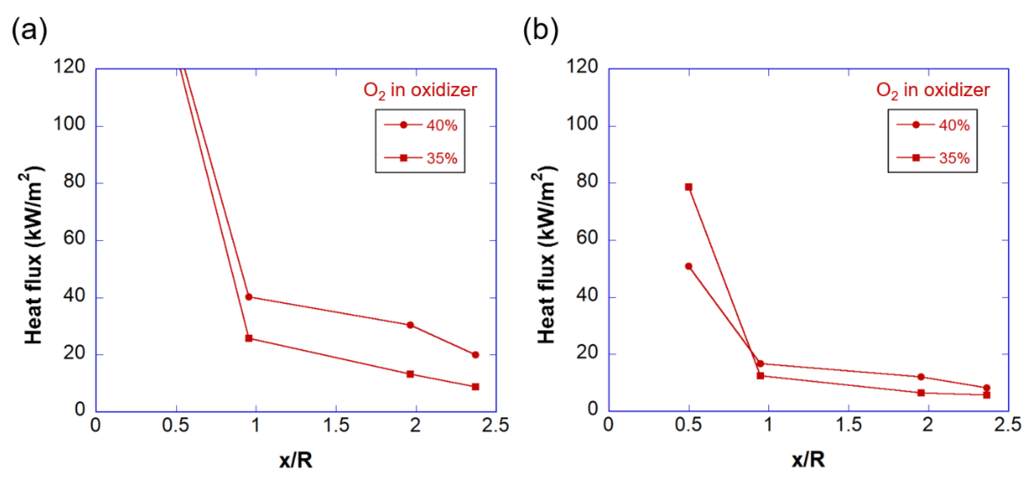
3.2. Temperature and Heat Flux

In the temperature distribution inside the combustion chamber for air combustion in Figure 7a, a high-temperature region radially spread out appears at an upstream position close to the burner because of the action of the swirler. Compared with a similar type of oxy-PC burner [26], the upstream, high-temperature region covers a larger distance in the radial direction. At 50% load, the flame does not spread to the sidewall; therefore, a low-temperature region appears near the sidewall (r/R = 1); the region originates from an upstream location. After x/R = 2, where recirculating flow occurs, a conical, low-temperature region occurs near the central axis, which is more clearly observed at 50% load.
In oxy-fuel combustion (Figure 7b), a high-temperature region occurs along the central axis and shows an elongated balloon shape, similar to the temperature distribution of Oh and Noh [23]. Furthermore, the flow rate and flame fullness decrease but, except for the upstream region (x/R < 1), the temperature near the wall is distributed not lower than that for air combustion because of the effect of gas radiation.
Oxy-fuel FGR (Figure 7c) also shows a temperature distribution similar to that of air combustion (Figure 7a) because the oxidizer is supplied through the swirler. At 100% load, higher temperature distribution is observed upstream compared with air combustion, which is consistent with the trend shown in the glowing characteristics of refractories observed in the flame images (Figure 4 and Figure 6a). In the flame photographs of 50% load (Figure 6b), the flame was detached from the refractory, and the temperature was low at the upstream (x/R = 0.5) combustion chamber wall.
Figure 8 compares the wall heat flux distribution for different combustion modes at 3.5% of exhaust oxygen. FGR is the result obtained under the condition of 40% O2 of the oxidizer. Air and FGR combustion have a large heat flux value upstream. The heat flux rapidly decreases up to the vicinity of x/R = 1 and then gradually decreases after x/R = 1. Quantitatively, FGR has a higher heat flux value than air combustion in the upstream region. Oxy-fuel combustion shows an even distribution of heat flux in the flow direction. For this combustion, while the heat flux is lower than other modes in the upstream region, it is more than 60% larger in the downstream region where x/R exceeds 2.
Figure 9 compares heat flux distributions for different flue gas O2 for oxy-fuel combustion. For 100% load (Figure 9a), the heat flux for 3.5% of O2 is considerably higher than the data for low O2 in the downstream region. This appears to be because the effect of convection becomes more important as it goes downstream. As thermal radiation is proportional to the fourth power of temperature and convection is proportional to the first power, the effect of convection becomes more important as it flows downstream (see Figure 7). Since convective heat transfer is proportional to the flow rate, it increases as the flue-gas O2 increases. The result for 50% load presented in Figure 9b shows the same trend, but the effect of flue-gas O2 is considerably reduced.
Figure 10 shows the heat flux distribution of FGR for different recirculation rates when the exhaust O2 is 3.5%. At a low recirculation rate (40% O2 in the oxidizer), the heat flux is high compared with 35% O2 in the downstream region (x/R > 1). At 50% load (Figure 10b), the heat flux around x/R = 0.5 at 35% O2 is higher than that at 40% O2. In the front image (Figure 6b) taken at 50% load, a flame with high luminance is visible around the center at 40% O2, and this flame appears to have given rise to a high radiant heat flux downstream.

3.3. Emissions

In a previous study, in a 50-kW class model experiment, CO2 concentrations of about 90% (at full load) and about 85% (at a partial load) were obtained [13]. In this study, high CO2 concentrations were obtained at 50% and 100% loads in oxy-fuel combustion by improving gas tightness and by controlling the blower with an inverter (Figure 11). For both oxy-fuel and FGR combustion, a high concentration of CO2 close to the theoretical value, over 93% at the range of 2–5% of exhaust gas O2, was obtained; this range of exhaust gas O2 is typical of boiler operating conditions.
CO decreased when the supply of the oxidizer was sufficient, and it converged to a very low value in all combustion modes when the exhaust O2 exceeded 3.5% (Figure 12). CO is generally produced from a combustion reaction short of oxygen based on combustion fundamentals. In oxy-fuel combustion, CO2 can dissociate near the flame to generate CO [27,28]. Oxy-fuel and FGR combustion generated CO when the O2 amount supplied was close to stoichiometry. For both cases, more CO was detected at 50% load compared with 100% load. Relatively, the concentration of CO was high in FGR combustion at full load and in oxy-fuel combustion at a partial load.
NO accounts for about 95% of the nitrogen oxides generated in the boiler combustion chamber, and the rest comprises mostly NO2 and traces of N2O [9]. In this study, the concentration of NO was measured for the different combustion modes and is presented in Figure 12. In oxy-coal combustion, which is the combustion mode in boilers used for coal-fired power generation, there is no oxygen supplied from the air, so it is mostly fuel NOx [29,30]. Natural gas has almost no nitrogen component in fuel, so it is mostly thermal NOx and its origin is mainly through infiltration. Air infiltration in new boilers is about 2% to 4% and increases with aging [31].
In this study, by improving the airtightness of the system, NOx in oxy-fuel was significantly reduced compared with the data of the 50-kW model experiment. In the 50-kW model experiment, the NO concentration in oxy-fuel was 5 to 10 times that of air combustion depending on the combustion load [13]. The concentration of NO was suppressed to twice that for air combustion in oxy-fuel combustion and reduced to half of that for air combustion in FGR combustion (Figure 13a). In oxy-fuel combustion, flue gas was reduced more significantly compared with air combustion; therefore, NO emission per fuel volume was considerably lower (Figure 13b). In oxy-fuel combustion, the flow rate of flue gas is reduced to 1/8 of that of air combustion, so the concentration of NO seems to have increased (Figure 12a), but the total amount of emissions has decreased (Figure 13b).

4. Conclusions

In this study, the following conclusions were drawn from observations of the combustion characteristics of a 0.5 MW class furnace tube boiler installed with an oxy-fuel burner.
  • In oxy-natural-gas combustion without FGR, the flame temperature increases, and the gas radiation becomes stronger. Consequently, the extended flame of the coaxial combustor can heat the boiler combustion chamber designed for the air combustion flow rate.
  • In oxy-natural-gas FGR combustion, an O2 concentration exceeding the oxy-coal concentration was required for flame stabilization owing to the effect of moisture. In the boiler used in this study, a stable flame was obtained above 32% O2.
  • While flame delay was observed at a partial load in FGR combustion, it was not observed in the other combustion modes.
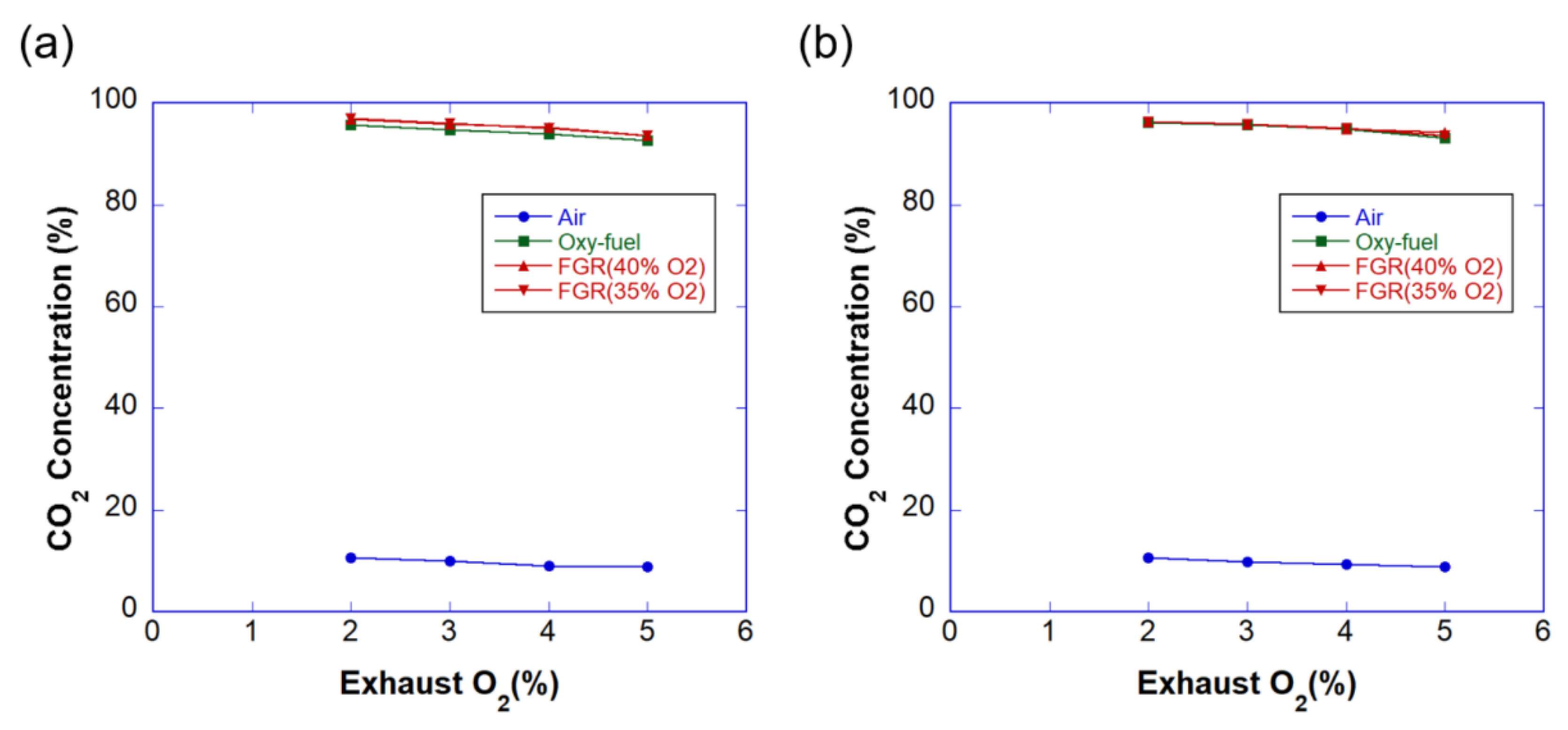
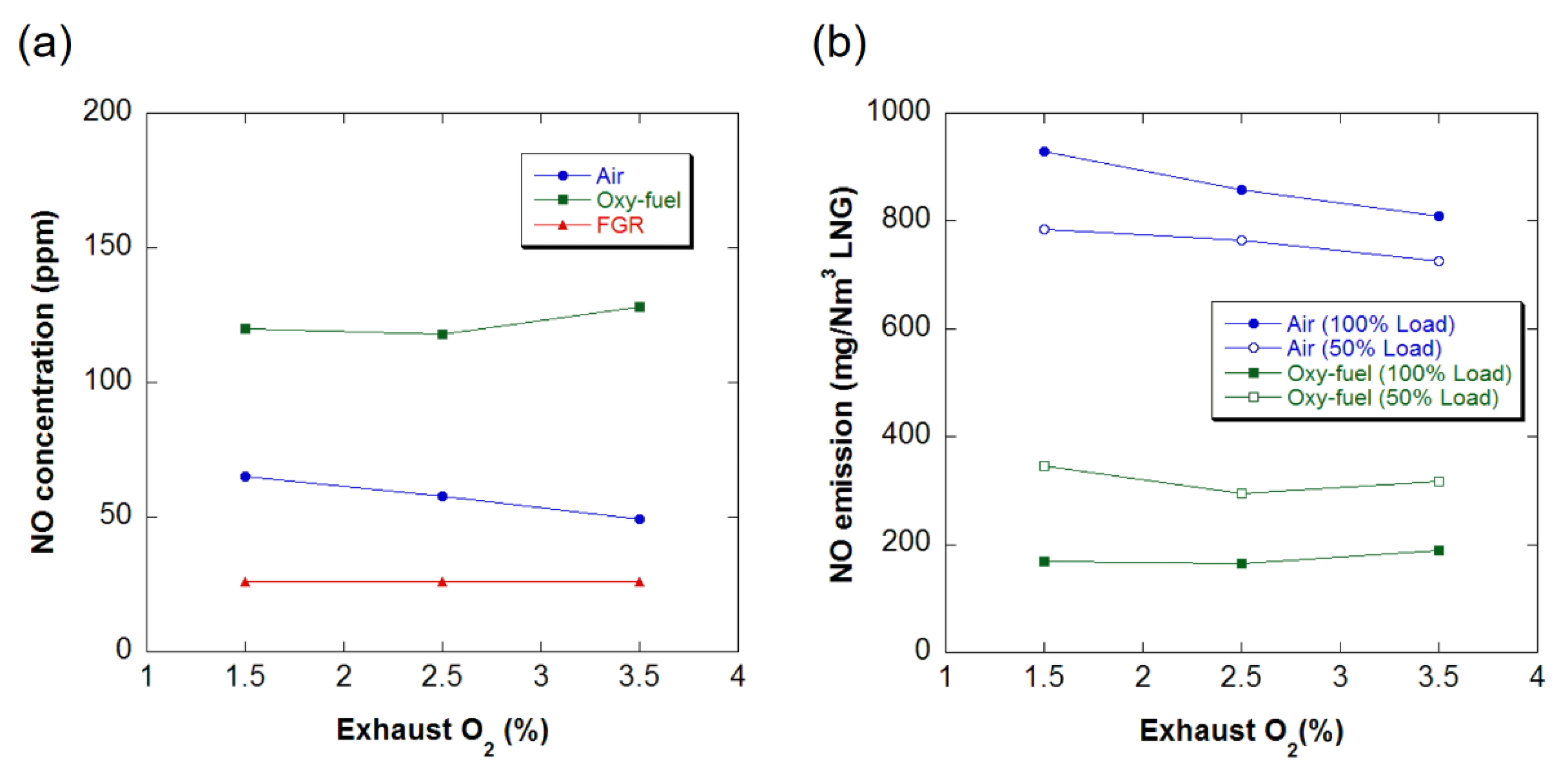
  • If the airtightness of the system is maintained, the concentration of CO2 in the exhaust gas of industrial boilers can be increased by more than 90% through oxy-fuel combustion. The emission of NOx can be considerably reduced by implementing the coaxial burner.

Author Contributions

Conceptualization, J.A. and H.-J.K.; methodology, J.A. and H.-J.K.; software, J.A.; validation, J.A. and H.-J.K.; formal analysis, J.A.; investigation, J.A.; resources, H.-J.K.; data curation, J.A.; writing—original draft preparation, J.A.; writing—review and editing, J.A.; visualization, J.A.; supervision, H.-J.K.; project administration, H.-J.K.; funding acquisition, H.-J.K. All authors have read and agreed to the published version of the manuscript.

Funding

This work was supported by the Korea Institute of Energy Technology Evaluation and Planning (KETEP) and the Ministry of Trade, Industry & Energy (MOTIE) of the Republic of Korea (No. 1415167167).

Institutional Review Board Statement

Not applicable.

Informed Consent Statement

Not applicable.

Data Availability Statement

Data is contained within this article.

Conflicts of Interest

The authors declare no conflict of interest.

Nomenclature

FGRflue gas recirculation
PCpulverized coal
rradial coordinate at the combustion chamber [m]
Rradius of the combustion chamber [m]
xstreamwise coordinate from the burner [m]

References

  1. Nemitallah, M.A.; Habib, M.A.; Badr, H.M.; Said, S.A.; Jamal, A.; Ben-Mansour, R.; Mokheimer, E.M.A.; Mezghani, K. Oxy-fuel combustion technology: Current status, applications, and trends. Int. J. Energy Res. 2017, 41, 1670–1708. [Google Scholar] [CrossRef]
  2. Shirmohammadi, R.; Aslani, A.; Ghasempour, R. Challenges of carbon capture technologies deployment in developing countries. Sustain. Energy Technol. Assessm. 2020, 42, 100837. [Google Scholar] [CrossRef]
  3. Bui, M.; Adjiman, C.S.; Bardow, A.; Anthony, E.J.; Brown, S.; Fennell, P.S.; Fuss, S.; Galindo, A.; Hackett, L.A.; Hallett, J.P.; et al. Carbon capture and storage (CCS): The way forward. Energy Environ. Sci. 2018, 11, 1062–1176. [Google Scholar] [CrossRef] [Green Version]
  4. Hu, X.; Xie, J.; Cai, W.; Wang, R. Thermodynamic effects of cycling carbon injectivity in shale reservoirs. J. Petrol. Sci. Eng. 2020, 195, 107717. [Google Scholar] [CrossRef]
  5. Davarpanah, A.; Mirshekari, B. Experimental investigation and mathematical modeling of gas diffusivity by carbon dioxide and methane kinetic adsorption. Ind. Eng. Chem. Res. 2019, 58, 12392–12400. [Google Scholar] [CrossRef]
  6. Markewitz, P.; Leitner, W.; Linssen, J.; Zapp, P.; Müller, T.; Schreiber, A. Worldwide innovations in the development of carbon capture technologies and the utilization of CO2. Energy Environ. Sci. 2013, 5, 7281–7385. [Google Scholar] [CrossRef] [Green Version]
  7. Wu, H.B.; Xu, M.X.; Li, Y.B.; Wu, J.H.; Shen, J.C.; Liao, H. Experimental research on the process of compression and purification of CO2 in oxy-fuel combustion. Appl. Energy 2020, 259, 114123. [Google Scholar] [CrossRef]
  8. Shirmohammadi, R.; Aslani, A.; Ghasempour, R.; Romeo, L.M.; Petrakopoulou, F. Process design and thermoeconomic evaluation of a CO2 liquefaction process driven by waste exhaust heat recovery for an industrial CO2 capture and utilization plant. J. Therm. Anal. Calorim. 2021. [Google Scholar] [CrossRef]
  9. Stanger, R.; Wall, T.; Spörl, R.; Paneru, M.; Grathwohl, S.; Weidmann, M.; Scheffknecht, G.; McDonald, D.; Myöhänen, K.; Ritvanen, J.; et al. Oxy-fuel combustion for CO2 capture in power plants. Int. J. Greenhouse Gas Control 2015, 40, 55–125. [Google Scholar] [CrossRef]
  10. Geem, Z.W.; Kim, J.H. Optimal energy mix with renewable portfolio standards in Korea. Sustainability 2016, 8, 423. [Google Scholar] [CrossRef] [Green Version]
  11. Park, N.-B.; Park, S.Y.; Kim, J.J.; Choi, D.G.; Yun, B.Y.; Hong, J.C. Technical and economic potential of highly efficient boiler technologies in the Korean industrial sector. Energy 2017, 121, 884–891. [Google Scholar] [CrossRef]
  12. Ahn, J.; Kim, H.J.; Choi, K.S. Combustion characteristics of oxy-fuel burners for CO2 capturing boilers. J. Therm. Sci. Tech. 2009, 4, 408–413. [Google Scholar] [CrossRef] [Green Version]
  13. Ahn, J.; Kim, H.J.; Choi, K.S. Oxy-fuel combustion boiler for CO2 capturing: 50kW-class model test. J. Mech. Sci. Tech. 2010, 24, 2135–2141. [Google Scholar] [CrossRef]
  14. Ehyaei, M.A.; Ahmadi, A.; Rosen, M.A.; Davarpanah, A. Thermodynamic optimization of a geothermal power plant with a genetic algorithm in two stages. Processes 2020, 8, 1277. [Google Scholar] [CrossRef]
  15. Ahn, J.; Kim, H.J. Combustion and heat transfer characteristics at the combustion chamber of an oxy-fuel boiler for CO2 capturing: A numerical simulation. Progress CFD 2011, 11, 210–215. [Google Scholar]
  16. Marcano, N.; Recourt, P.; Tsiava, R.; Laurent, J.; Lethier, S.; Deveaux, M.; Bouvarel, A.; Quet, J.P. Oxy-combustion at Lacq CCS pilot plant: Preliminary analysis of burner-boiler performance. In Proceedings of the 2nd Oxyfuel Combustion Conference (OCC2), Yeppoon, Australia, 11–16 September 2011. [Google Scholar]
  17. Burchhardt, U. Übersicht zu Tests und Ergebnissen der Oxyfuel-Forschungsanlage Schwarze Pumpe. In Proceedings of the Public Final Project Meeting of the German Research Project “ADECOS-Komponenten”, Cottbus, Germany, 7–8 May 2014. [Google Scholar]
  18. Rehfeldt, S.; Schiffer, F.P.; Weckes, P.; Bergins, C.; Tigges, K.D. Oxy-fuel combustion with Hitachi’s DST—Burner at Vattenfall’s 30MWth pilot plant at Schwarze Pumpe. In Proceedings of the 2nd Oxyfuel Combustion Conference (OCC2), Yeppoon, Australia, 11–16 September 2011. [Google Scholar]
  19. Sturgeon, D. Oxy-coal burner technology development. In Proceedings of the 2nd Oxyfuel Combustion Conference (OCC2), Yeppoon, Australia, 11–16 September 2011. [Google Scholar]
  20. Choi, S.; Kim, T.Y.; Kim, H.K.; Koo, J.; Kim, J.S.; Kwon, O.C. Properties of inverse non-premixed pure O2/CH4 coflow flames in a model combustor. Energy 2015, 93, 1105–1115. [Google Scholar] [CrossRef]
  21. Kim, H.K.; Kim, Y.; Lee, S.M.; Ahn, K.Y. Studies on combustion characteristics and flame length of turbulent oxy-fuel flames. Energy Fuel 2007, 21, 1459–1467. [Google Scholar] [CrossRef]
  22. Oh, J.; Noh, D. Flame characteristics of a non-premixed oxy-fuel jet in a lab-scale furnace. Energy 2015, 81, 328–345. [Google Scholar] [CrossRef]
  23. Becker, L.G.; Kosaka, H.; Böhm, B.; Knappstein, R.; Habermehl, M.; Kneer, R.; Janicka, J.; Dreizler, A. Experimental investigation of flame stabilization inside the quarl of an oxyfuel swirl burner. Fuel 2017, 201, 124–135. [Google Scholar] [CrossRef]
  24. Hees, J.; Zabrodiec, D.; Massmeyer, A.; Hatzfeld, O.; Kneer, R. Experimental investigation into the influence of the oxygen concentration on a pulverized coal swirl flame in oxy-fuel atmosphere. Fuel 2019, 240, 64–74. [Google Scholar] [CrossRef]
  25. Massmeyer, A.; Zabrodiec, D.; Hees, J.; Kreitzberg, T.; Hatzfeld, O.; Kneer, R. Flame pattern analysis for 60kWth flames under conventional air-fired and oxy-fuel conditions for two different types of coal. Fuel 2020, 271, 117457. [Google Scholar] [CrossRef]
  26. Silva, R.C.; Krautz, H.J. Combustion measurements of type-1 pulverized coal flames operating under oxy-fired conditions. Fuel Process Tech. 2018, 171, 232–247. [Google Scholar] [CrossRef]
  27. Toftegaard, M.B.; Brix, J.; Jensen, P.A.; Glarborg, P.; Jensen, A.D. Oxyfuel combustion of solid fuels. Prog. Energy Combust. Sci. 2010, 36, 581–625. [Google Scholar] [CrossRef]
  28. Toporov, D.; Bocian, P.; Heil, P.; Kellermann, A.; Stadler, H.; Tschunko, S.; Förster, M.; Kneer, R. Detailed investigation of a pulverized fuel swirl flame in CO2/O2 atmosphere. Combust. Flame 2008, 155, 605–618. [Google Scholar] [CrossRef]
  29. Andersson, K.; Normann, F.; Johnsson, F.; Leckner, B. NO emission during oxy-fuel combustion of lignite. Ind. Eng. Chem. Res. 2008, 47, 1835–1845. [Google Scholar] [CrossRef]
  30. Gaber, C.; Schluckner, C.; Wachter, P.; Demuth, M.; Hochenauer, C. Experimental study on the influence of the nitrogen concentration in the oxidizer on NOx and CO emissions during the oxy-fuel combustion of natural gas. Energy 2021, 214, 118905. [Google Scholar] [CrossRef]
  31. Kather, A.; Scheffknecht, G. Review: The oxy-coal process with cryogenic oxygen supply. Naturwissenschaften 2009, 96, 993–1010. [Google Scholar] [CrossRef] [Green Version]
Figure 1. Oxy-fuel flue gas recirculation (FGR) combustion boiler for CO2 capture.
Energies 14 04333 g001
Figure 2. Oxy-fuel/air/FGR convertible burner.
Energies 14 04333 g002
Figure 3. Experimental setup: (a) a schematic and (b) a photograph.
Energies 14 04333 g003
Figure 4. Flame images (front and side) for different combustion loads and exhaust O2 concentrations for air combustion.
Energies 14 04333 g004
Figure 5. Flame images (front and side) for different combustion loads and exhaust O2 concentrations for oxy-fuel combustion.
Energies 14 04333 g005
Figure 6. Flame images (front and side) for different recirculation rates in oxy-fuel FGR combustion: (a) 100% and (b) 50% loads.
Energies 14 04333 g006
Figure 7. Temperature distribution inside the combustion chamber for (a) air combustion, (b) oxy-fuel combustion, and (c) oxy-fuel FGR combustion.
Energies 14 04333 g007
Figure 8. Heat flux to the combustion chamber wall for different combustion modes for (a) 100% and (b) 50% loads.
Energies 14 04333 g008
Figure 9. Heat flux from the oxy-fuel flame to the combustion chamber wall for different flue gas O2 concentrations: (a) 100% and (b) 50% loads.
Energies 14 04333 g009
Figure 10. Heat flux from the oxy-fuel FGR flame to the combustion chamber wall for different O2 concentrations in the oxidizer for (a) 100% and (b) 50% loads.
Energies 14 04333 g010
Figure 11. CO2 concentration in the exhaust gas at (a) 100% and (b) 50% loads.
Energies 14 04333 g011
Figure 12. CO emission in parts per million (ppm) at (a) 100% and (b) 50% loads.
Energies 14 04333 g012
Figure 13. NO emission. (a) NO concentration at 100% load and (b) NO emission per unit fuel consumption.
Energies 14 04333 g013
Publisher’s Note: MDPI stays neutral with regard to jurisdictional claims in published maps and institutional affiliations.

