1. Introduction
Methods for supplying the oxidizer and fuel propellant to a liquid rocket engine (LRE) are largely classified into pressurized gas feed systems and turbopump feed systems [
1].
The pressurized gas feed LRE system uses a storage tank with helium gas (GHe) or nitrogen gas (GN2) at high pressure to pressurize and supply the propellants to the main combustion chamber. This system has the advantages of simple design, low cost, and ease of manufacturing, but, as a disadvantage, it is unable to obtain a higher thrust because of the low pressure of the main combustion chamber. Therefore, this system is suitable for a small LRE with low thrust.
The turbopump feed LRE system drives an oxidizer pump and fuel pump to supply the propellants at high pressure to the main combustion chamber using a turbine, which is powered by hot gas exhausted from the gas generator or preburner. This system has the advantage of a higher thrust than the pressurized gas feed LRE system. It is suitable for a large LRE system, driving greater payloads over larger distances. Turbopump feed LRE systems are roughly classified into two types: an open cycle using a gas generator and a staged combustion cycle using a fuel-rich or oxidizer-rich preburner (ORPB).
The open cycle LRE burns 1.5–7% of the total oxidizer and fuel propellant in the gas generator and drives the turbine using the combustion gas, which is discarded to the outside [
1]. This system is applied in the Saturn V F-1 and Space-X Merlin series of the U.S.; Soyuz RD-107/108 and RD-0110 of Russia; and 75 tonf and 7 tonf LREs of the Korea Space Launch Vehicle-II (called Nuri-ho). The maximum specific impulse in open-cycle LREs on Space-X Merlin 1D is about 282 s at sea level [
2].
In a staged combustion cycle LRE (SCCE), which uses kerosene as the fuel, an ORPB is generally used due to its numerous thermodynamic advantages [
3]. In this study, kerosene was used as the fuel, and liquid oxygen (LOX) was used as the oxidizer; therefore, an ORPB was the main subject of this study. In the ORPB, a small fraction of fuel and all of the oxidizer in the propellant tanks are supplied and burned. After ignition, the generated oxidizer-rich combustion gas at high temperature and high pressure drives the turbine of the turbopump, and then the gas is supplied to the main combustion chamber for reburning. In the process of reburning without discarding the generated combustion gas, the SCCE system using the ORPB has a 5% higher specific impulse than the open-cycle LRE using the gas generator [
4]. This system was used in RD-170/180/191, RD-0124, RD-58M, NK33, RD-120, and RD-8. These LREs were made in Russia and Ukraine, and their specific impulses are ~340 s or more.
The injector types in LREs are mainly classified as impinging injectors and coaxial swirl injectors [
5].
In the impinging injector, fuel and oxidizer propellants are injected through orifices, and they collide with each other in the main combustion chamber. Due to the collision momentum of the propellant, the oxidizer and the fuel are atomized and mixed. This impinging injector is easy to manufacture because of its simple shape and structure but has the disadvantage of being susceptible to combustion instability if the atomization performance is poor.
The swirl coaxial injector supplies the oxidizer and fuel in the same axial direction and has tangential holes (inlet) and discharge nozzles (outlet) at right angles. The pressurized propellants are introduced through the tangential holes and move to the nozzle with swirling due to their flow velocity and the shape of the vortex chamber. After the ejection, a conical thin liquid film with both axial and tangential velocity components is formed. This injector has a good atomization performance and has the advantage of decreasing the combustion instability under various operating conditions of the LRE. The temperature of the combustion gas is ~3000 K in the main combustion chamber. This high temperature can melt all of the surrounding materials; therefore, a method of lowering the temperature is essential [
6,
7].
The turbines of the turbopump used in the SCCE are driven by hot gas emitted from the ORPB; the temperature of the hot gas should be limited to <700 K because the acceptable margin of this temperature does not put a thermal load on the material of the turbine blades. This temperature is generated at an O/F of approximately 60, but ignition is difficult at this O/F. Therefore, it is necessary to perform ignition and combustion at an O/F of 10–20 and cool the generated combustion gas to a low temperature in the injector itself.
In this paper, a swirl coaxial jet injector is presented in which ignition and combustion are performed in the inner chamber of the injector, driven by the coaxial swirl of the fuel and oxidizer. The hot gas is cooled from high to low temperature outside the injector by the oxidizer jet using a second cooling channel.
This injector was used in the RD-170/180/191 series in Russia and RD-120 in Ukraine. These LREs were SCCE systems and applied ORPBs using liquid oxygen and kerosene as propellants. Detailed information on the injector and research related to the combustion test have been difficult to find in the literature. Recently, studies on the swirl coaxial jet injector were performed in the United States, China, and Korea.
Kim et al. performed a combustion test for a period of 10 s using a small-scale single injector with a fuel mass flow rate of 5 g/s and an oxidizer mass flow rate of 300 g/s for a small-scale ORPB. To ensure the combustion stability at the beginning of ignition and combustion, a combustion test was carried out in two steps. One was in auxiliary mode with a relatively low oxidizer mass flow rate for 1 s. The other was in the main mode with a nominal oxidizer mass flow rate for 9 s. The pressure of the combustion chamber was 10 MPa [
8].
Ha et al. designed and manufactured a swirl coaxial jet injector with a total mass flow rate of 5.6 kg/s and performed a combustion test using only an ORPB without other devices, such as a turbopump and control valves. High-frequency combustion instability at 1100 Hz, which was the 1L acoustic mode, and low-frequency combustion instability at 100 Hz occurred during combustion testing. The high-frequency combustion instability was suppressed by reducing the diameter and applying a turbulence ring in the combustion chamber [
9].
Long et al. produced a prototype of an ORPB and injectors for the main combustion chamber at Purdue University. The propellants of the ORPB were liquid oxygen and hydrogen. The propellants of the main combustion chamber were the oxidizer-rich hot gas generated by the ORPB and RP-1. This system was subjected to a combustion test with a torch igniter using the propellants GH2/GOX; however, no subsequent research has been published [
10].
Lioi et al. used CFD to perform linear acoustic analysis of an ORPB assembly with turbines in the turbopump. The ORPB assembly was similar to that of RD-170. The results show that the speed of sound and resulting frequencies were approximately 20% higher than would be expected from ideal gas assumptions [
11]. Lioi also undertook linear acoustic analysis of the main combustion chamber in the SCCE system. Acoustic waves excited in the main chamber propagated upstream and interacted with the oxidizer dome, where they were partially damped by the flow distributor. They determined that the largest contributor to damping was the increased transport of acoustic energy out of the domain [
12].
Using CFD, Garg et al. compared ideal and real gases in the combustion field in high-pressure environments and varied the O/F of the single-element injector in the ORPB. The study showed that the ideal gas law was not suitable for modeling flow and flame fields in the injector domain. The study emphasized that the real gas model was necessary to accurately model thermodynamic properties [
13].
Previous studies have mainly focused on numerical analysis, non-reacting flow, and combustion tests with a small-scale single injector; however, it is necessary to study the combustion characteristics of multi-element injectors in the LRE system using combustion tests.
In this study, combustion characteristics were investigated through combustion tests representing actual combustion environments. Injectors were theoretically designed [
14], and three types were manufactured with different momentum ratios. The momentum ratio is described in Equation (1), which defines the momentum ratio based on the velocity of the generated combustion gas (
) and the mass flow rates of the oxidizer (
) and fuel (
) in the inner chamber of the injector to the velocity of the emitted low-temperature liquid oxidizer (
) and the mass flow rate of the oxidizer in the second cooling channel (
).
2. Experimental Hardware and Methods
2.1. Swirl Coaxial Jet Injector
Three types of swirl coaxial jet injectors with varying momentum ratios were designed and manufactured by mechanical processing [
15]. As shown in
Figure 1, the injector consists of a fuel injector and an oxidizer injector. The fuel injector has four tangential holes at clockwise intervals of 90°. The fuel is supplied through these holes, swirls clockwise in the passage, and flows into the nozzle. The fuel is thinly sprayed from the fuel nozzle at an angle of 80–90° into the middle of the injector. The oxidizer injector consists of 8 tangential holes and 12 cooling channels. The supplied oxidizer swirls through the tangential holes with 23% of the total oxidizer mass flow rate and is injected into the oxidizer injector. The oxidizer tangential holes are located in two rows of four in the clockwise direction and are arranged at intervals of 45° to avoid interference with the swirling flow. The purpose of the oxidizer cooling channel is to cool the combustion field inside the injector from above 2000 K and the hot combustion gas outside the injector to below 700 K. There are a total of 12 channels, each with a rectangular shape.
As shown in
Figure 2, the oxidizer and fuel are mixed and atomized in a small space in the inner chamber of the injector according to their mass flow rates and pressures. The proportion of the oxidizer and fuel in the inner chamber, the core O/F, was set to 14, which was expected to result in a temperature of ~2000 K based on CEA calculations. This high temperature can melt the material (SUS316L) of internal injector parts, such as the fuel post and fuel nozzle. If these parts are damaged and hit the pipe at high speed or are supplied to the turbine and sparks are generated by the fast rotation of the turbine, an explosion may occur due to the oxidizer-rich conditions combined with high pressure and high temperature.
Because the burning in the inner chamber occurs under high-temperature and high-pressure conditions, 77% of the oxidizer from outside was allowed to cool the injector through the oxidizer cooling channel to prevent thermal shock and load inside the injector and, in particular, to prevent damage to the fuel post.
As shown in
Table 1, the tangential holes of A-, B-, and C-type fuel injectors are 0.68 mm in diameter; four tangential holes are spaced 90° clockwise. The diameter of the fuel nozzle was designed to be 3 mm. The three types of oxidizer injectors were designed with respective tangential hole and nozzle diameters of 1.6 and 8 mm (A type); 1.64 and 7.5 mm (B type); and 1.65 and 8 mm (C type). The cross-sectional areas of the second cooling channel of the oxidizer are 1.5 × 2.2 mm
2 in the A and B types and 1.5 × 2.0 mm
2 in the C type.
2.2. Oxidizer-Rich Preburner (ORPB)
The ORPB can be divided into three main components: a head assembly, a combustion chamber assembly, and a turbulence ring.
The head assembly consists of a 3/8-inch pipe, a fuel manifold, seven injectors, an injector guide, and a mixer manufactured by mechanical processing. As shown in
Figure 3a, fuel is supplied through the 3/8-inch pipe and then distributed uniformly by the manifold to the seven injectors, which are arranged in two concentric circles: one is located at the center, and six are located on the perimeter. The injector guide is a device that allows the seven injectors to be mounted between the fuel manifold and the mixer to maintain a specific angle. The mixer is welded and mounted at the end of the injector guide and is located inside the combustion chamber during the assembly of the head and combustion chamber. It acts as a device that can burn continuously and stably without interfering with the flow of other combustion gases along its length. The material of the mixer is chrome copper (CrCu), which does not react with high concentrations of oxidizer under high-pressure and high-temperature conditions.
The second component is the combustion chamber assembly, which consists of an oxidizer manifold and a combustion chamber. As shown in
Figure 3a, the oxidizer is supplied to an oxidizer manifold with an inner diameter of 30 mm, which supplies 95% of the oxidizer to the injectors, and the remaining 5% is used to cool the combustion chamber through the cooling channel; however, the combustion chamber was not cooled in this study.
The third component is the turbulence ring. This device serves as a node point to suppress combustion instability under the 1L mode and allows the hot combustion gases to mix evenly before they are supplied to the turbine. The turbulence ring is detachable using a screw with an inner diameter of 43 mm.
2.3. Measurement
To measure the amount of propellants supplied to the ORPB, a turbine-type flow meter manufactured by Flowmetrics (FM series) was installed at the rear of the fuel pump of the turbopump, and a mass flow meter manufactured by Micro Motion (ELITE series) was installed in the main pipe for the oxidizer and fuel.
To evaluate the combustion dynamics, piezoelectric-type sensors manufactured by PCB Piezotronics were installed in the propellant manifolds and the combustion chamber, as shown in
Figure 3a. Pressure fluctuations in the oxidizer manifold and fuel manifold were measured by 102A11 and 101A04 sensors, respectively. These sensors were mounted with flush mounts. To measure the fluctuations in the combustion chamber, helium-bleed and water-cooled dynamic pressure sensors were mounted with a flush mount (123A24).
To measure the static pressure, a strain gauge-type pressure transducer (Honeywell TJE) was used. The temperature sensors use T-type thermocouples to measure the oxidizer temperature and K-type thermocouples for the fuel and combustion chamber.
In previous research, the SUS material was reported to react with oxidizer-rich gas under high-pressure and high-temperature conditions. Moon et al. proposed using Inconel as material [
16]. K-type temperature sensors with Inconel were installed between the rear of the turbulence ring and the pipe of the turbine inlet, which has a lower velocity than the combustion chamber.
In the measurement system, a dynamic pressure sensor and an acceleration sensor were sampled at 25.6 kHz using an IEPE/AC/DC voltage-digitizer module in Series 6000 of Pacific Instruments. In addition, the static pressure and temperature sensor were sampled at 1 kHz using a thermocouple/voltage scanner and strain amp-digitizer with an auto-gain module.
All valve sequences to supply the propellants were preset on the Programmable Logic Controller (PLC) of Rockwell Automation to perform combustion tests.
2.4. Test Conditions
To perform combustion tests with combustion pressures above 20 MPaA, the propellants must be supplied to the ORPB at a minimum pressure of 21 MPaA. For pressurized systems using GHe or GN2, there is an instrumental limitation to reliably supply propellants at a high pressure. Therefore, in this study, the propellants were supplied to the ORPB with a pressure of 21 MPaA or more using the turbopump.
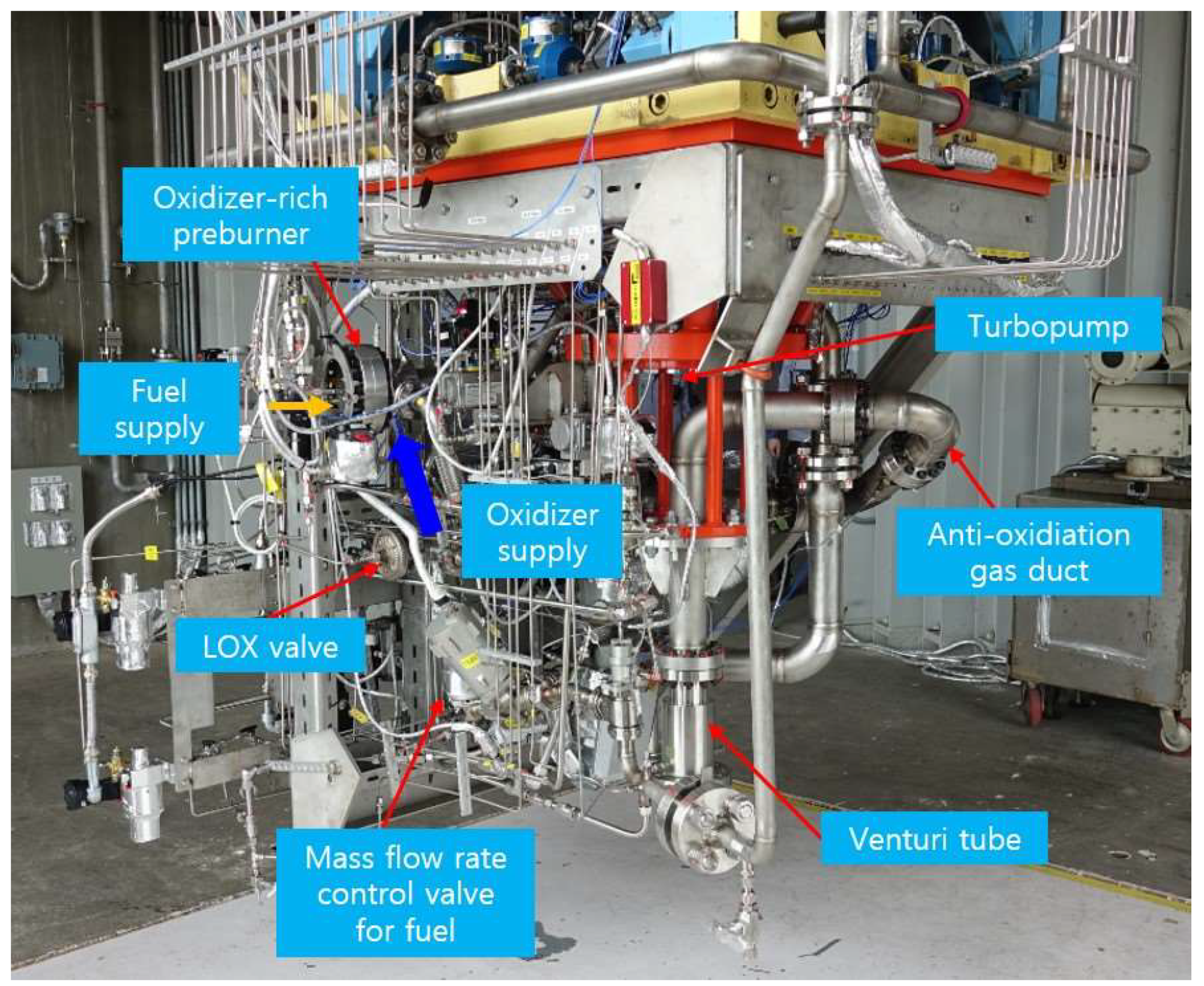
As shown in
Figure 4, a technical demonstration model (TDM) was constructed with a turbopump, solenoid valves, control valves, a venturi tube, propellant pipes, and an ORPB. This TDM does not have a main combustion chamber. A venturi tube is installed in place of the main combustion chamber, and the diameter of the venturi tube is equal to the size of the nozzle throat of the main combustion chamber. Because of the risk of system damage due to the malfunction of the injector or other devices, the combustion test was carried out by applying a venturi tube in place of the main combustion chamber in the LRE system, which is a 9 tonf staged combustion cycle engine. This system is called the power-pack system. The method of ignition used triethylaluminum (TEAL) to prevent a hard start and to replicate the real environment.
The test sequence was automatically performed by the PLC control system with a preset. The starting turbine was operated at 11,000 RPM through 10 MPaA of GHe to supply the propellants from the main pipes to the oxidizer and fuel pump. The oxidizer and TEAL in the fuel pipe were burned, generating combustion gases to power the turbine. Oxidizer and fuel were supplied at 17.6 kg/s and 0.29 kg/s, respectively, by driving the turbine with combustion gas at high temperature and high pressure. The differential pressure between the fuel or oxidizer manifold and the combustion chamber was about 1.5 MPaA. To prevent damage to the ORPB and peripheral devices due to unexpected increases in pressure and temperature during ignition, the flow control valve was adjusted to supply fuel at the designed target flow after 2 s. As shown in
Table 2, the combustion pressure at the design point was 22 MPaA, with a combustion gas temperature of 688 K and a turbopump speed of 29,000 RPM. In addition, the theoretical combustion characteristic velocity was 1785 m/s; further details are provided in
Section 3.3.
Three interchangeable head assemblies were manufactured for the injectors designed with different momentum ratios, and one combustion chamber and one turbulence ring were used. After the combustion test was completed, the head assembly was replaced. Combustion tests were carried out six times in total for each type, with the first taking 5 s and the second taking 30 s, to determine the combustion characteristics for different momentum ratios of the injector.
3. Results and Discussion
3.1. Flow Characteristics in Ambient and Combustion Conditions
Twelve injectors of A, B, and C types with different momentum ratios were manufactured, and each was subjected to a cold flow test. Then, seven injectors with similar flow rates were selected and used in the ORPB. Cold flow tests are essential to confirm the hydrodynamic and geometric properties of the injectors using water as a working fluid, which simulates a propellant under ambient pressure conditions.
The discharge coefficient () is expressed in Equation (2), where is the mass flow rate of propellants, is the area of the tangential hole of the injector, is the density of propellants, and is the difference in pressure between the water supply pressure and the ambient pressure.
As shown in
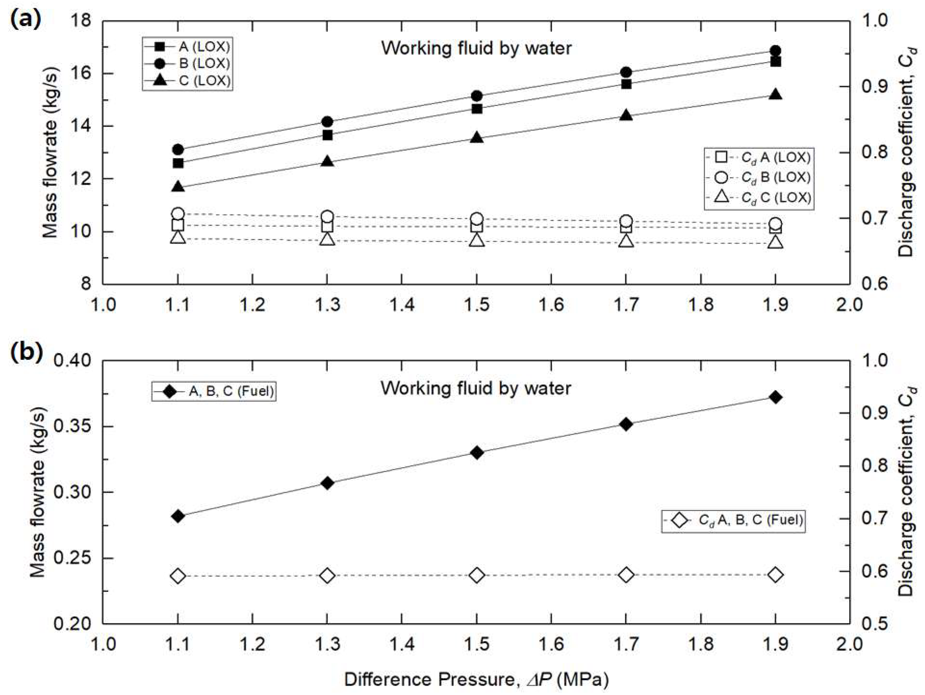
Figure 5, the mass flow rate of the fuel injector for all types increased from 0.28 to 0.37 kg/s as the differential pressure increased from 1.1 to 1.9 MPa. The discharge coefficient was maintained at a constant value of 0.6. The reason for this setting is that, as shown in
Table 1, all fuel injectors have the same shape and dimensions, with four tangential holes with diameters of 0.68 mm.
The mass flow rate of the oxidizer injector increased in proportion to the oxidizer area as the differential pressure increased from 1.1 to 1.9 MPa. The oxidizer areas of A, B, and C were 396, 402, and 372 mm2, respectively. The oxidizer area of A was 1.4% smaller than that of B and 6.1% larger than that of C. The discharge coefficient ranged from 0.66 to 0.7 and remained constant regardless of the increase in pressure.
There was little or no change in the discharge coefficient when the differential pressure increased. As the differential pressure increased, the mass flow rate increased in proportion to the oxidizer area. In addition, under the same differential pressure condition, the larger the oxidizer area, the larger the mass flow rate and discharge coefficient. These results are similar to those of previous studies [
5,
6,
17].
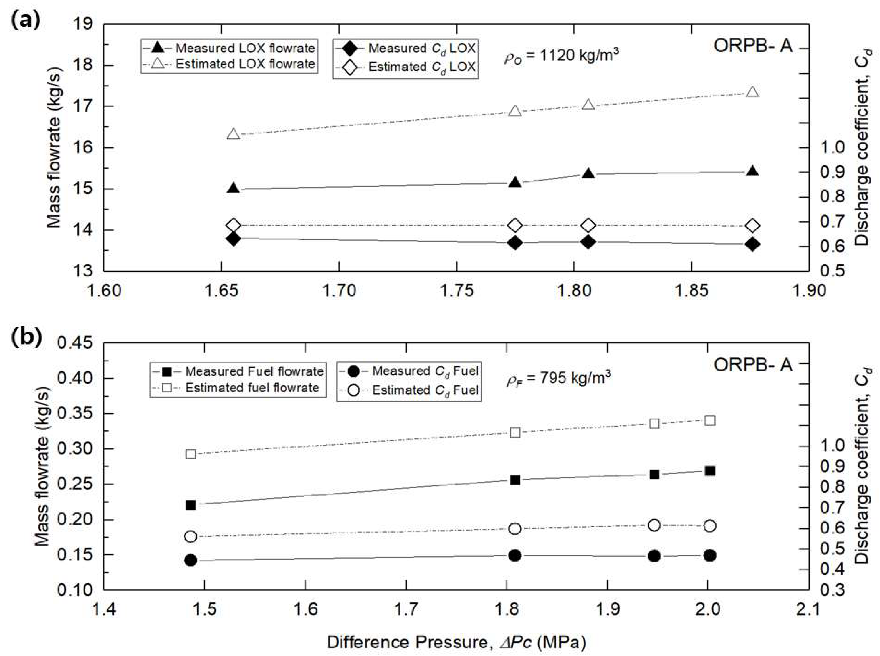
Figure 6 compares the mass flow rate estimated in the cold flow test and the mass flow rate measured in the combustion test of the ORPB-A. For the estimated mass flow rate, the constant value obtained through the cold flow test was used as the discharge coefficient, and the density was calculated as the actual propellant density.
The density of the fuel was . At a differential pressure of 1.8 MPaA between the fuel manifold and the combustion chamber, the measured mass flow rate was 0.26 kg/s, and the discharge coefficient was 0.47. The estimated mass flow rate was 0.32 kg/s, and the discharge coefficient was 0.60. The difference in the fuel mass flow rate supplied was about 19%.
The density of the oxidizer was . At a differential pressure of 1.88 MPaA between the oxidizer manifold and the combustion chamber, the measured mass flow rate was 15.42 kg/s, and the discharge coefficient was 0.61. The estimated mass flow rate was 17.33 kg/s, and the discharge coefficient was 0.69. The difference in the oxidizer mass flow rate supplied was about 11%.
As mentioned in previous studies [
18,
19], the phenomenon in which the supplied propellant is less than the estimated value in the actual combustion environment occurs because of the increasing volume changes from the propellant liquid to the gas due to the combustion at high pressure and high temperature, which is different from ambient conditions. This combustion backpressure results in a blocking effect on the mass flow rate. In particular, the fuel mass flow rate was lower than that of the oxidizer due to the long passage of the fuel injector, and a hot combustion field then formed within the injector. Therefore, the swirl coaxial jet injector was designed to account for the deviation of the mass flow rate in the combustion environment. In addition, the hydraulic characteristics were confirmed by the cold flow test.
3.2. Combustion Test
In this study, the results of each type of combustion test for 30 s were compared.
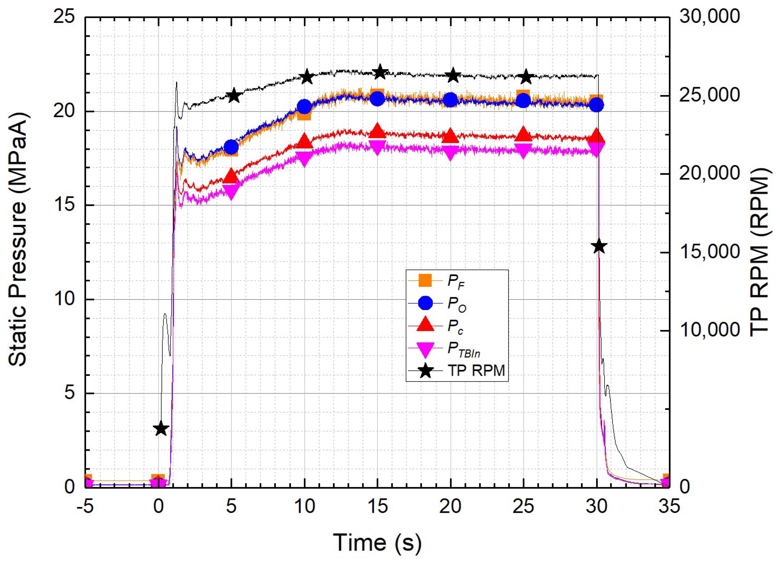
Figure 7 shows that the TP RPM increased to 11,000 in 0.5 s when driving the turbine with helium gas. The fuel and oxidizer pumps started to operate and the pressure rose, supplying the TEAL for ignition and propellants to the ORPB. In 0.9 s, the TEAL supplied through the fuel tangential holes and oxidizer supplied through the oxidizer tangential holes reacted to initiate combustion in the inner chamber of the injectors, and the combustion pressure rose rapidly to 16 MPaA. This increase in combustion pressure increased the turbine of the turbopump to over 20,000 RPM, strongly driving the fuel and oxidizer pumps and supplying the fuel and oxidizer at over 17 MPaA to the ORPB.
Pressure variations of more than 10% occurred due to the initial combustion shock, which was stabilized within 1 s. To prevent damage to the ORPB due to initial combustion shock and rapid changes in propellant supply pressure, the combustion test was started at a pressure of 16 MPaA, which is lower than the design pressure. Then, in the combustion test, the fuel mass flow rate was increased by changing the opening degree of the fuel flow control valve for 8 s from 2 s after the shock was reduced.
Figure 7 shows the static pressure–time history of the ORPB-A. The fuel manifold (
), oxidizer manifold (
), combustion chamber (
), turbopump inlet (
), and TP RPM are shown. It can be seen that the static pressure of the propellant and the static pressure of the combustion chamber were proportional to the increase in TP RPM. The average combustion chamber pressure at the combustion time of 29.0–29.5 s was 18.5 MPaA. The differences in pressure between the combustion chamber and the fuel and oxidizer manifolds were 1.9 and 1.8 MPaA, respectively. At this time, the supplied fuel mass flow rate was 0.26 kg/s, and the oxidizer mass flow rate was 15.3 kg/s, with an O/F of about 59. In the expected combustion test conditions shown in
Table 1, the combustion test was performed by increasing the differential pressure between the supply pressure of the propellant and the pressure of the combustion chamber to more than 0.4 MPaA. This is because, as explained in
Section 3.1, in actual combustion, a smaller than expected flow rate is supplied at the same differential pressure. In addition, the differential pressure between the combustion chamber and the inlet of the turbopump turbine was 0.7 MPaA, which reflects the effect of the installation of the turbulence ring.
Figure 8 shows the temperature–time history of the ORPB-A. When the starting turbine was driven, the oxidizer (
) and fuel (
) were supplied at 107 and 273 K, respectively. It can be confirmed that these were supplied without a change in temperature until the completion of combustion. The combustion chamber was not equipped with temperature sensors because the high-temperature and high-pressure oxidizer-rich combustion gas was supplied quickly to the turbine at a high flow rate. According to a previous study, if temperature sensors are installed in the combustion chamber of the preburner, they may be damaged due to the high-temperature and high-pressure oxidizer-rich gas, resulting in an explosion [
20]. If a 3/16-inch temperature sensor is installed in the combustion chamber, it must protrude 10 mm from the combustion chamber wall. The material of the probe for the temperature sensor should be Inconel rather than SUS.
To measure the temperature of the combustion gas, temperature sensors were installed at intervals of 180° in the inlet pipe of the turbine () rather than the combustion chamber, and a probe was mounted so that it protruded 10 mm from the pipe wall. The temperature of oxidizer-rich combustion gas at the turbine inlet was found to be 686 K. Because this was the temperature measured on the pipe wall, the temperature of the combustion gas actually supplied to the turbine can be expected to be higher than this value. In addition, it was expected that the temperature of the combustion chamber would be higher than the turbine inlet temperature. It can be seen that the turbine inlet temperature decreased from 315 to 280 K within 1 s following the start of combustion. It can also be seen that the combustion test sequence comprised the opening of the oxidizer valve followed by the opening of the fuel valve to allow burning. After 20 s, the temperature of decreased from 698 to 682 K, which confirmed that the probe was inclined toward the pipe wall due to the rapid flow rate of the combustion gas. The turbine outlet temperature () was 140 K before combustion started because the piping was precooled by the oxidizer. Following ignition, the temperature increased, and the turbine outlet temperature was found to be 620 K.
3.3. Combustion Performance
In general, specific thrust is used as a factor to evaluate the performance of a liquid rocket engine; however, in this study, the characteristic velocity was used as an evaluation factor for the combustion performance [
21].
As shown in Equation (3), the characteristic velocity
is expressed as the relationship between the combustion chamber pressure, the throat of the nozzle area, and the total mass flow rates of the oxidizer (
) and fuel (
) [
3,
18,
19]. In this study, the stagnation pressure in the combustion chamber was replaced by the static pressure (
) measured in the combustion test because the dynamic pressure was very low (0.01 MPaA). The stagnation pressure in the combustion chamber was replaced by the static pressure measured through by the combustion test, and the throat of the nozzle area was replaced by the area of the turbulence ring (
).
Figure 9 shows the change in the characteristic velocity, combustion pressure, and total mass flow rate according to the momentum ratio for the period from 29.0 s to 29.5 s, which was the combustion stabilization period. The average and standard deviation were obtained by sampling 500 data points during a 0.5 s period. MR 3.0 represents ORPB-A, MR 3.3 represents ORPB-C, and MR 3.7 represents ORPB-B.
In MR 3.0, the characteristic velocity was 1747 m/s, the combustion pressure was 18.5 MPaA, and the total mass flow rate was 15.4 kg/s. In MR 3.3, the characteristic velocity was 1722 m/s, the combustion pressure was 18.5 MPaA, and the total flow rate was 15.6 kg/s. In MR 3.7, the characteristic velocity was 1715 m/s, the combustion pressure was 18.3 MPaA, and the total flow rate was 15.5 kg/s.
As shown in
Figure 9, MR 3.0 showed uniform and stable combustion performance with smaller standard deviations than those of MR 3.3 and MR 3.7. In addition, MR 3.0 had a relatively high characteristic velocity with the lowest total mass flow rate, which formed at the highest combustion pressure.
Figure 10 shows the TP RPM, turbine inlet temperature, and O/F according to the momentum ratio in the combustion stabilization period of 29.0–29.5 s. The TP RPM was maintained at about 26,500 regardless of the momentum ratio. It can be seen that the fuel pump and the oxidizer pump of the turbopump supplied the fuel and oxidizer mass flow rates to the ORPB at the same discharge pressure. The turbine inlet temperature and O/F were 686 K and 57 for MR 3.0, 677 K and 58 for MR 3.3, and 665 K and 59 for MR 3.7. The relational expression in Equation (4) can be inferred from the turbine inlet temperature (
) and O/F. In all ORPBs, the turbine inlet temperature was below the target value of 688 K. Additional tests are required to accurately determine the temperature of the combustion chamber; these will be carried out in the future.
The ratio of the theoretical characteristic velocity (
) to the measured characteristic velocity (
) from the combustion test is defined as
and is used as a measure of the combustion efficiency. As shown in Equation (5), this is calculated by performing a combustion test to measure the flow rate of the propellant supplied and the pressure of the combustion chamber, and it is calculated as:
Figure 11 shows the combustion efficiency according to the momentum ratio for 30 s of the combustion test, showing five typical sections. Each section is represented by the average value of data acquired for 0.5 s. From 4.0 to 4.5 s, the measured combustion efficiency was low at all momentum ratios because the combustion test was performed with a lower mass flow rate to prevent damage to the preburner by adjusting the opening degree of the fuel control flow valve. Because the low flow rate of the fuel eventually lowered the combustion pressure, the combustion efficiency was the lowest.
Because the combustion efficiency is directly proportional to the combustion pressure rather than the change in the propellant flow rate, the combustion efficiency increases as the combustion pressure increases. From 24.0 to 24.5 s and from 29.0 to 29.5 s, the combustion efficiency was as high as 96–98%. It can be seen that the combustion was stable and that the combustion efficiency was the highest for MR 3.0 and the lowest for MR 3.7.
3.4. Combustion Instability
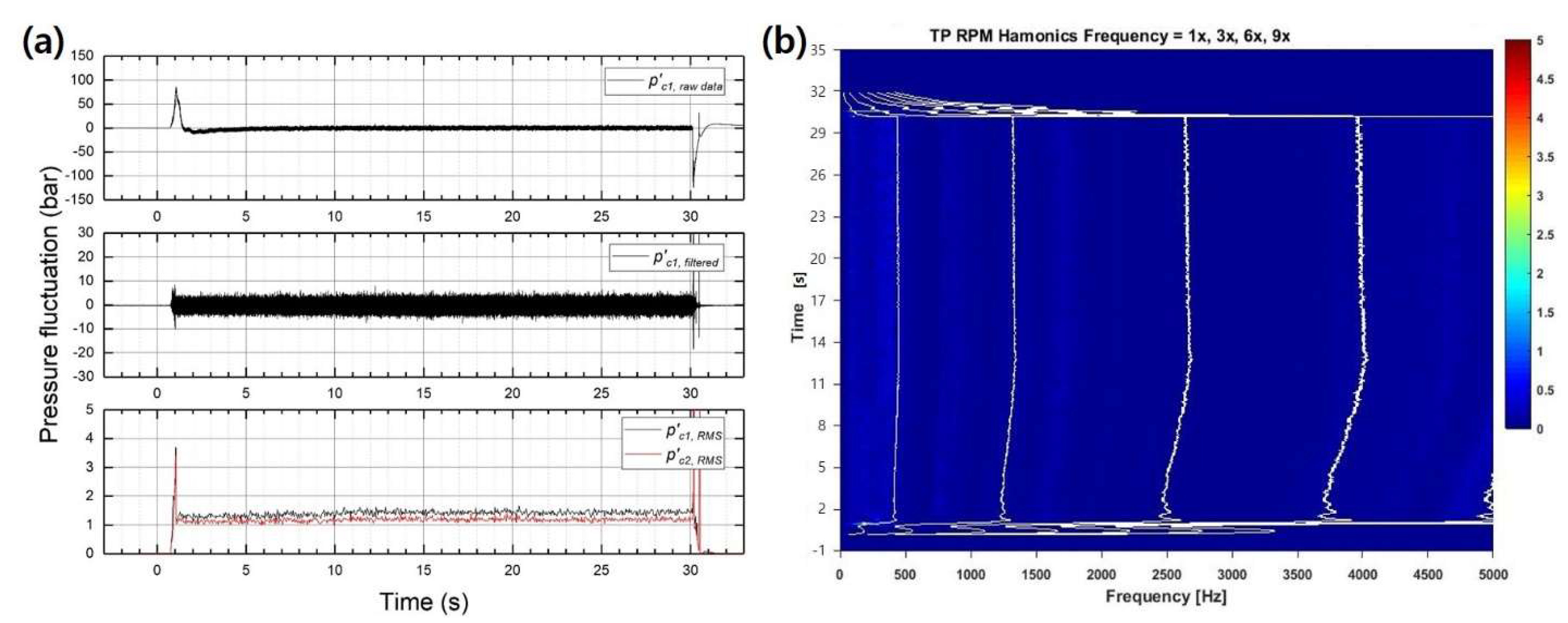
Figure 12 shows the dynamic pressure–time history of the ORPB-A. The raw data in
Figure 12a were measured at 25.6 kHz by a dynamic pressure sensor using an IEPE/AC/DC voltage-digitizer module in the PI system, and the filtered data were band-pass filtered at 50–10,000 Hz to remove DC components and signal noise. RMS was calculated as a block size of 1024 (40 ms) from the filtered data. As shown in
Figure 3, two dynamic pressure sensors were installed in the combustion chamber in the longitudinal direction.
represents the dynamic pressure sensor mounted in the center of the combustion chamber, and
sensors were mounted at 50 mm intervals in the longitudinal direction of the combustion chamber. At start-up, the RMS values were 3.7 and 3.3 bar, respectively. The dynamic pressure remained stable as the combustion proceeded. RMS values for the 29.0–29.5 s period were 1.5 and 1.2 bar, respectively.
was about 0.8%, and the combustion was stable. In general, if the RMS value of dynamic pressure versus static pressure does not exceed 5%, it is said to have combustion stability [
1].
Figure 12b shows the frequency (x), combustion time (y), and amplitude (z) as a waterfall graph. This was used to check for a characteristic frequency or a resonant frequency, which is abnormal behavior at 50–5000 Hz. The white lines represent the TP RPM harmonics frequency, indicated as 1×, 3×, 6×, and 9×. This was used to distinguish the frequency generated by the TP drive.
Several previous studies have stressed the importance of preventing the high-frequency combustion instability that occurs during combustion. This must be studied carefully in the development of a liquid rocket engine. If high-frequency combustion instability occurs, it may destroy the liquid rocket system [
1,
4,
22,
23]. Combustion instability occurs due to coupling between the high frequency generated in the acoustic wave by combustion and the natural frequency of the combustion chamber; energy is instantaneously amplified, thus damaging the system. It is difficult to understand the theoretical mechanism of high-frequency combustion instability.
Therefore, a combustion test necessary is necessary to check whether high-frequency combustion instability occurs. If high-frequency combustion instability is found to occur, the frequencies must be decoupled using a reduction device such as a baffle and a resonator, thus stabilizing combustion. In this study, a combustion test was performed with a power pack system without a main combustion chamber to prevent damage to the engine system due to combustion instability.
Using Equation (6), the natural frequencies (
) calculated in
Table 3, namely, the 1L (745 Hz), 2L (1489 Hz), 1T (3956 Hz), and 2T (6562 Hz) modes of the acoustic wave generated when the ORPB burned the propellants, were theoretically calculated. In this study,
is the speed of sound and has a value of 490 m/s;
is the transversal eigenvalue;
are the longitudinal, tangential, and radial mode numbers; and
and
are the radius and length of the combustion chamber [
23]. According to R. Pirk [
24], a comparison was made between the calculated frequency and the actual frequency measured during the test; a difference of 0.1–10% was found. In particular, in 1L, the calculated and test values were almost the same, with a difference of 0.1%. As shown in
Figure 12b, the amplitude was below 1, and it was confirmed that no specific frequency caused high-frequency combustion instability. The three types of combustion instability were less than 0.8%, and it was confirmed that combustion instability did not occur during the combustion test. In addition, no more than 5% dynamic pressure was generated in all injectors, and no specific frequency was generated.
4. Summary and Conclusions
The combustion characteristics of a 9 tonf SCCE with an ORPB were experimentally studied at different momentum ratios of multi-element injectors. An injector was designed in which a swirl coaxial jet is sprayed with a liquid fuel–liquid oxidizer–liquid oxidizer combination. The mixture was burned in the inner chamber inside the injector. To lower the temperature of the combustion gas, which exceeded 2000 K in the inner chamber, liquid oxidizer was supplied to the cooling channel outside the injector. To prevent the turbine blades from melting, the combustion gas was maintained below 700 K. To confirm the combustion characteristics at different momentum ratios of the high-temperature combustion gas inside the injector and the low-temperature liquid oxidizer outside the injector, three types of injectors were designed and manufactured with three momentum ratios: MR 3.0, MR 3.3, and MR 3.7.
Before performing the combustion test, a cold flow test using water was performed to identify the hydraulic characteristics of the injectors and the ORPB. In this study, the combustion test and the hydraulic characteristics using water were compared.
To minimize the possibility of engine system damage due to combustion instability, a venturi tube was used instead of a main combustion chamber, and combustion tests for the OPRB with seven injectors were performed. The OPRB was a separated head type. Following the combustion test, the injectors and the ORPB were inspected internally and externally, and the ORPB head was then replaced to perform the combustion test. In this study, the results of the combustion test for each type were compared for 30 s. For the ORPB-A, a combustion pressure of 18.5 MPaA, a fuel mass flow rate of 0.26 kg/s, an oxidizer mass flow rate of 15.3 kg/s, and a turbine inlet temperature of 686 K were obtained during the combustion stability period of 29.0–29.5 s.
The combustion efficiency was 98% for MR 3.0 (ORPB-A), which was superior to that obtained with the other momentum ratios. Furthermore, during the combustion test for MR 3.0, the fluctuations in the characteristic velocity, combustion pressure, and propellant mass flow rate were low, indicating that a stable combustion test was performed. The three types of combustion instability were less than 0.8%, and it was confirmed that combustion instability did not occur during the combustion test. In addition, after the combustion test, the fuel post in the injectors was inspected. Examination of ORPB-A, -B, and -C confirmed that the fuel post did not melt or suffer thermal damage. Based on the results of this study, the ORPB-A (MR 3.0) injector was determined to be suitable for a 9 tonf SCCE, and a combustion test was then performed by applying a main combustion chamber [
25]. In future studies, research on the combustion characteristics according to the length of the combustion chamber of the ORPB will be performed, and the combustion characteristics of the separated head ORPB and the integrated head ORPB will be compared.


