1. Introduction
Bucket wheel excavators (BWEs) are the main equipment used in open pit lignite mines, both for lignite and overburden rock excavation. The mining operators are facing various technical problems, among which the energy consumption and operating power represent the main issues in terms of productivity and operating costs.
Knowledge of the laws governing mechanical cutting, which represent interdependencies between different parameters including teeth geometry, material, bucket shape, and tooth placement layout, is highly significant in the analysis of power and energy aspects.
The appropriate operation of the BWEs is influenced, among other parameters, by the energy consumption and the rational utilization of the actuating power of the bucket wheel. The underloading or overloading of the bucket wheel actuating system are both inappropriate for the safe and efficient use of the involved equipment. The specific energy (SE) represents the work needed to excavate one rock unit of volume/mass [
1]. SE represents one of the key criteria for the assessment of a rock-excavating system’s efficiency and optimum condition, and for the estimation of its cutting rate [
2].
In this respect, the establishment of the characteristics of both qualitative and quantitative mechanical rock cutting must be performed on the basis of experimentally obtained data, supported by theory, and validated through field measurements. Various authors have developed theoretical models for the problem of rock cutting. Evans suggested a pattern [
3] for calculating the cutting force derived from the rocks’ compressive and tensile strengths, the depth of cut, and the bit geometry. He further improved this model for point attack bits [
4], retaining most of his earlier concepts and theory. Nishimatsu [
5] proposed a theory based on the application of the Mohr-Coulomb failure criterion during chip formation, considering the shear strength as the most crucial parameter. Authors of [
6] introduced a theoretical-empirical cutting approach, where the interaction between the rock and the cutting tool is highlighted in a zero-degree angle cutting scenario. In the study [
7], a detailed comparative analysis of the cutting force was conducted in the case of conical pick cutting mechanisms, based on nearly 200 test results of several different rock materials. Numerous studies using linear cutting machines (LCM) were conducted to evaluate parameters of excavating machines. Paper [
8] investigates the optimum set-up for spacing and depth in the case of a tunnel boring machine cutting tool, using several linear cutting experiments conducted for various speed and placement scenarios. Copur et al. [
9] studied the results of various cutting configurations and in situ conditions when using conical picks, demonstrating the ratio between the decrease of SE and cutting depth increase, along with an increased production of chips. Authors of [
10] conducted research on linear cutting that focused on rock fragment particularities in connection with SE and cutting force. They concluded that there is an inverse ratio between SE and the coarseness index, and a direct relationship between the cutting forces and the mean particle.
In recent years, the rock cutting task was also successfully simulated using computer software, with the use of either the discrete element method (DEM) or the finite element method (FEM). The discrete element method (DEM) was used in [
11] to investigate the effects of the cutting parameters (angle of the cone-shaped pick, the angular speed of the drum, and the traction speed) on the cutting force of the cone-shaped pick in a coal-cutting procedure. Several cutting simulations and full-scale tests using DEM were conducted to demonstrate the effects of set-up parameters and pick geometry on the cutting process in [
12]. The finite element method (FEM) was used to create a numerical model of rock cutting to assess the debris size and cutting forces variation in relation to rake angle and cutting speed [
13,
14], in order to find the effect of depth of cut [
15] or speed of cut [
16] on specific energy consumption. In the paper [
17], the coupled discrete/finite element model of rock cutting was used for several numeric simulations of an LCM test in the case of a single TBM disc. The comparative results of simulations versus theoretical and in situ data enable a better understanding of the rock cutting process and represent a useful optimization and design tool. A numerical simulation of a 2D rock-cutting model using DEM is presented in [
18]. It shows the main physical phenomenon of rock sample-tool interaction, emphasizing rock failure where the main cutting parameters are well-correlated, both in qualitative and quantitative aspects, with theoretical assumptions and experimental results. Further simulations in 3D are planned to validate the results obtained. Papers [
19] and [
20] extend the use of DEM to 3D, performing simulations of Brazilian and UCS tests, followed by cutting simulations of roadheaders and TBMs. Numerical results are compared with data available from experiments.
Due to the advances in modeling and simulation software, rock fragmentation by mechanical tools has been modeled and simulated using up-to-date numerical, computer-aided methods, with the aim of replacing laboratory tests and the closed-form analytical or empirical formulae by examining the basic phenomena at the micro level. In paper [
21], a rock-cutting simulation method was proposed based on the theory of smooth particle hydrodynamics, using the Drucker-Prager yield criterion to estimate the crisp behavior of rock and the cumulative damage model to simulate the rock splitting process. The results were compared with experimental ones, in terms of SE and cutting force. Study [
22] deals with an estimation of the cutting forces acting on the gouge tool. The induced tensile failure of the crushed area expansion term is introduced, which is an analytical model used for a more accurate estimation of the peak force acting on chisel picks during rock cutting. The results related to the link between cutting forces and cutting parameters (cutting depth, width, and rake angle) offer a more precise estimation of experimental results as compared to older models.
The compact poly-crystalline diamond bits (PDC), which are the smallest cutting tool employed in soft-to-medium hardness rock drilling, is studied in paper [
23] by analyzing the effects of the rotation angle, back rake angle, depth of cut, and the rock properties on the breaking process. The theoretical assumptions were validated by experimental lab tests on site assays.
Article [
24] deals with load variation by simulating the roadheader cutting head. The influence of slewing and rotating speed on load fluctuation and the SE consumption during cutting is subject to optimization. The adjustment of the swing speed of the cutting tool arm and of the cutting head rotation speed can ensure a highly efficient working state.
The importance of a method for the quick and relevant assessment of power requirements and energy consumption of the BWE in given mining geological conditions is evident. This concern is also treated in the literature.
Paper [
25] is focused on this issue, presenting theoretical, laboratory, and field measurements allowing for the understanding of cutting characteristics of Romanian open pit lignite mining, mainly regarding the specific energy consumption.
Paper [
26] is devoted to the connection of coal and overburden rocks cutting characteristics with the working regime of the excavators. A novel grapho-analytic methodology was proposed where the capacity of cutting and derived power are plotted on the same chart as functions of the specific resistance to cut, making it possible to set up an optimum working regime for the BWE by maximizing the excavation capacity while preventing drive motor overload. For the calculation of the optimal working regime for certain rock characteristics in the case of the most widely used excavators in Oltenia open pit coal mines, computer software was used. The authors used correlations between them derived from heuristic reasoning and closed-form relations.
The possibilities and choice of optimal operation conditions as a multi-criteria relation between the technical parameters of the BWE, the excavated rock cutting characteristics, and the particularities of the applied technology are analyzed in paper [
27], including the determination of the medium power of the bucket wheel drive during the working regime in order to achieve the highest efficiency of coal winning at the lowest cost.
Paper [
28] proposes a method for the determination of workability, taking into account the mechanical and physical characteristics of rock and coal in order to avoid the excavator being damaged by bucket wheel overloads exceeding the ones from the design phase. The authors claim that the most exact way to assess workability is by running tests of direct exploitation, which are run occasionally under conditions that are not possible to implement during the design stage.
In paper [
29], the authors claim the need for a metric that will be, at the present level of knowledge, the most objective and easy-to-measure; a metric that expresses rock-tool interaction, can be available immediately, and demonstrate that the volume of specific energy consumption fulfills these requirements and proposes a formula using direct measurement results.
The method proposed by the authors for the calculation of the actuating power of the BWE is based on the determination of the volume of material removed at an arm slewing cycle, using the numerical modeling of the specific volumetric energy for excavating the extracted material, by measuring both the testing rig in the laboratory and the slewing cycle time in real conditions.
2. Mechanical Cutting Characteristics of Coal
The relatively low strength of coal has made the mechanization of its breaking possible with the use of various machines such as bucket wheel excavators, shearers, shearer-loaders, roadheaders, and plows.
In the exploitation of energy resources in open-pit mines, BWEs are mainly used both for coal and overburden rock excavation. In this case, the rock gathering involves the interaction between the cutting part, which is the bucket wheel lip equipped with teeth, and the material to be excavated.
The breaking process causes a resultant force
R as a result of the interaction between the rock mass to be excavated and the cutting tooth. It can be organized on the cutting plane into two components: a component that acts along the direction of cutting of the cutting tooth F
x, called tangential force or cutting force, and a component that is perpendicular to the direction of cutting F
y, called normal force or penetration force. A lateral component F
z, which corresponds to the lateral strength of the coal in the breaking process, also acts on the tooth. The angle α between the front face of the tooth and the direction of the normal force F
y represents the rake angle. β is the angle between the bottom face of the tooth and the direction of the cutting (or tangential) force F
x, which is the clearance angle. The angle of attack, noted as θ, is created by the resultant force R direction and the cutting force F
x. The depth of cut is noted with h
0 (
Figure 1).
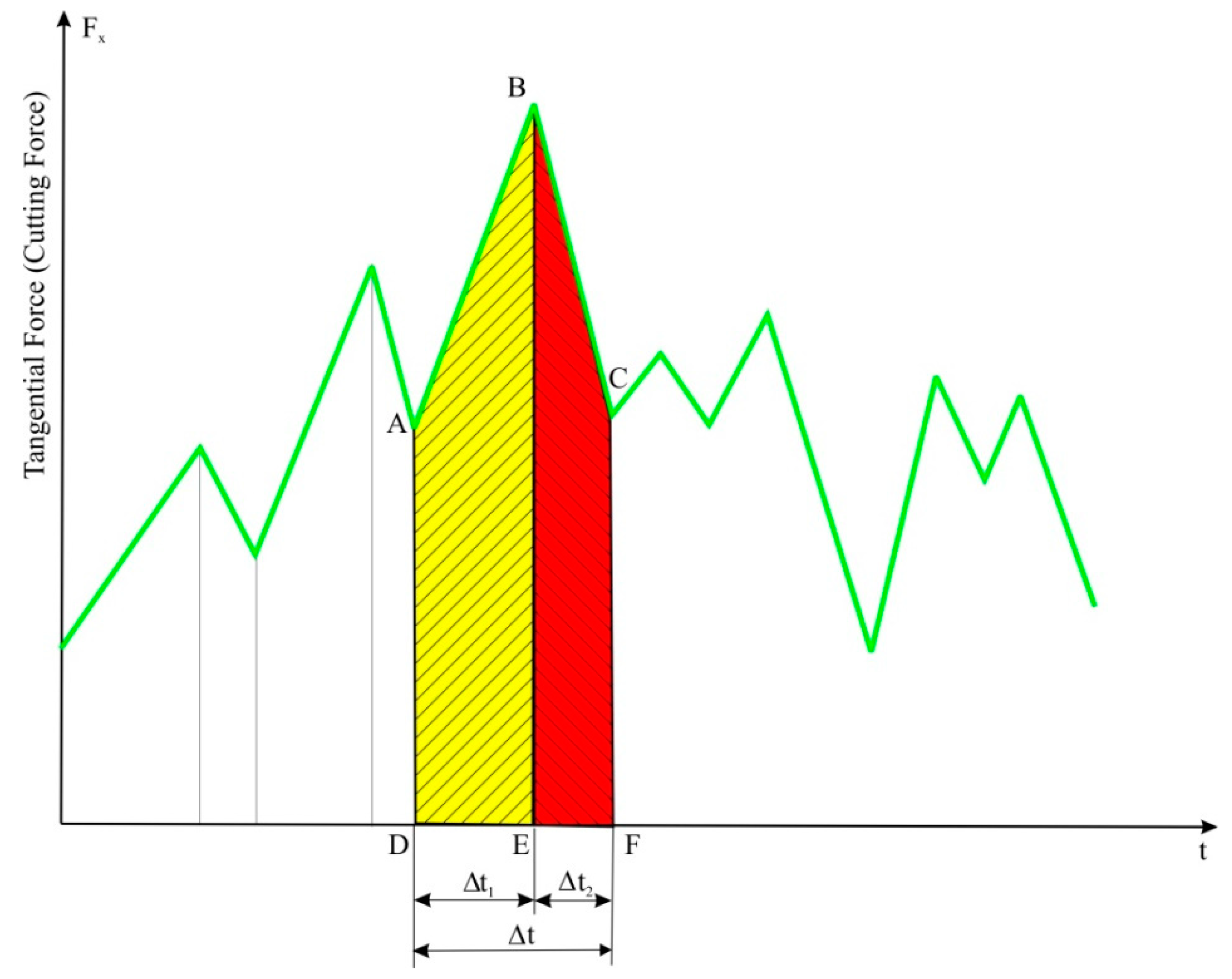
If the force variation in time is approximated by a polygonal line, then the portion of the graph between two successive minima (points A and C) corresponds to the formation and detachment of a chip from the rock mass (
Figure 2).
This process takes place within a time frame t. In the time interval t1, the tooth penetrates into the rock mass (A–B). The end of this period corresponds to the formation of the chip and is marked by a maximum force value. During the time period t2, the actual detachment of the chip takes place. This time range is between the maximum and minimum value of the tangential force (B–C).
For the two distinct time periods,
t1 and
t2, the corresponding values of mechanical work,
Lx1 and
Lx2 are:
where
vt is the cutting speed that can be considered approximately constant.
The appropriate impulses
Ix1 and
Ix2 are:
The mechanical work performed for the formation and removal of the chip is:
The area between the force line and the time axis is proportional to the energy transmitted by the tooth to the rock mass in the cutting process.
In
Figure 2, the ABED area is proportional to the energy consumed for chip formation, and the BCFE area is proportional to the energy consumed to overcome the friction during chip removal.
Chip formation during the breaking process of the rock mass is a phenomenon of comminution (crushing-grinding), which is dependent on a large number of parameters whose influence and variation have a random nature. To establish the link between the specific energy of the rock breaking and the size of the resulting chips, Charles’s relation [
30] is used, namely:
where:
is the specific energy related to a volume unit;
is the average dimension of the resulted chips;
is a constant of proportionality;
is a parameter depending on the nature of rock.
For
, we obtain Rittinger’s relation as follows:
where
D and
d are the initial and the final values of the particle’s size, respectively. It is computed as follows:
When the breaking from the rock mass is performed, its dimension being considerably greater than that of the chip’s, we can consider
and (6) use the following formula:
For Equation (4), in the case of
, we obtain the Kick-Kirpichev’s formula as follows:
where:
An intermediary hypothesis leads to Bond’s formula, obtained for
, as:
where:
In the case of
, this becomes:
The aforementioned formulae are useful for deriving the relationship between energy consumption and the grain size of the excavated rock. An interesting interpretation of Equation (7) is given in paper [
31], which identifies the parameter
as the specific cutting resistance A, relative to the depth of cut, as the ratio between the tangential force and the depth of cut, which is an invariant and represents a good metric of rock cuttability.
3. General Considerations for Cutting Coal with BWE
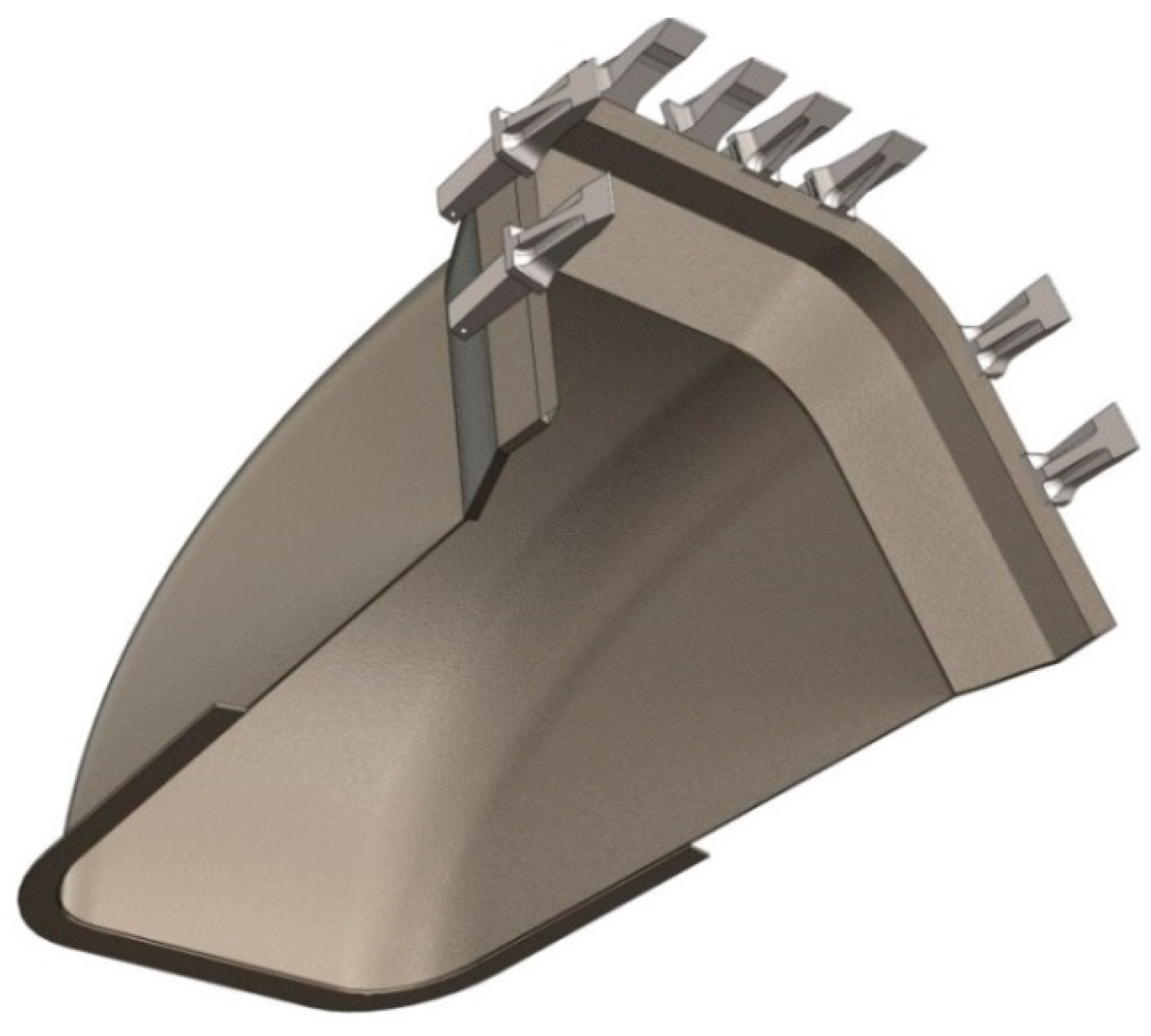
Bucket wheel excavators (BWEs), used for the removal of overburden and extraction of coal in open pit mines, are continuously-acting machines that cut the rock using a set of buckets fitted with teeth (
Figure 3) mounted on the bucket wheel (
Figure 4). At the same time, the buckets also collect and carry out the removed material until it is discharged into the on-board conveyor belt. Our model is based on the EsRc 1400 BWE, which has a bucket wheel with a cutting diameter of 11.5 m, equipped with 9 cutting-loading buckets. Each bucket is fitted with 8 cutting teeth.
Figure 4 shows the forces acting on the bucket-wheel buckets. Thus, the force tangents at the periphery of the bucket wheel are generated by the cutting process and only act on the buckets upon being in contact with the rock mass. Vertical forces correspond to the weight of the material loaded into the buckets and act on them until the excavated material is discharged onto the on-board conveyor. These forces are negligible relative to the tangential forces.
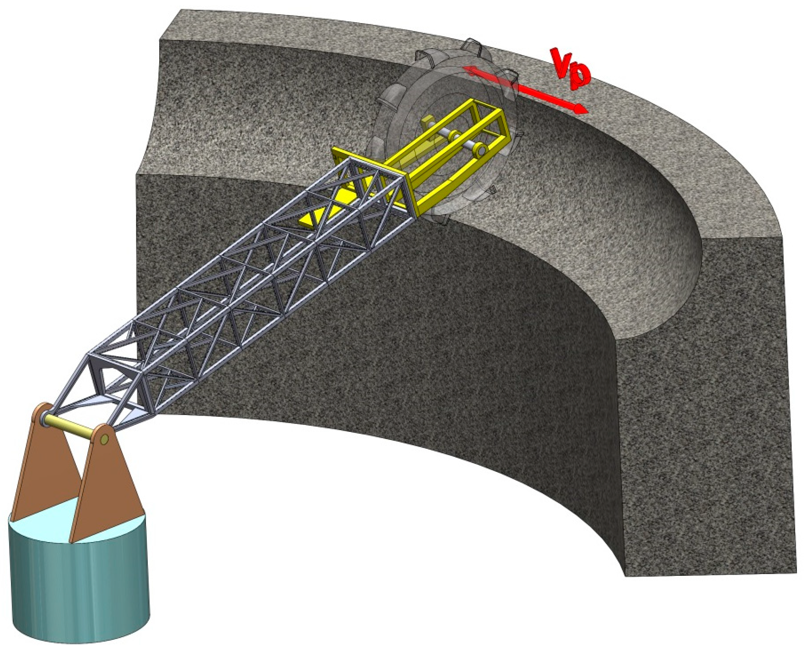
The bucket wheel is mounted on the excavator arm (boom), which performs a slewing motion with a speed V
p in a horizontal plane. This movement of the excavator arm allows the extraction of rock mass by slices, as visible in
Figure 5.
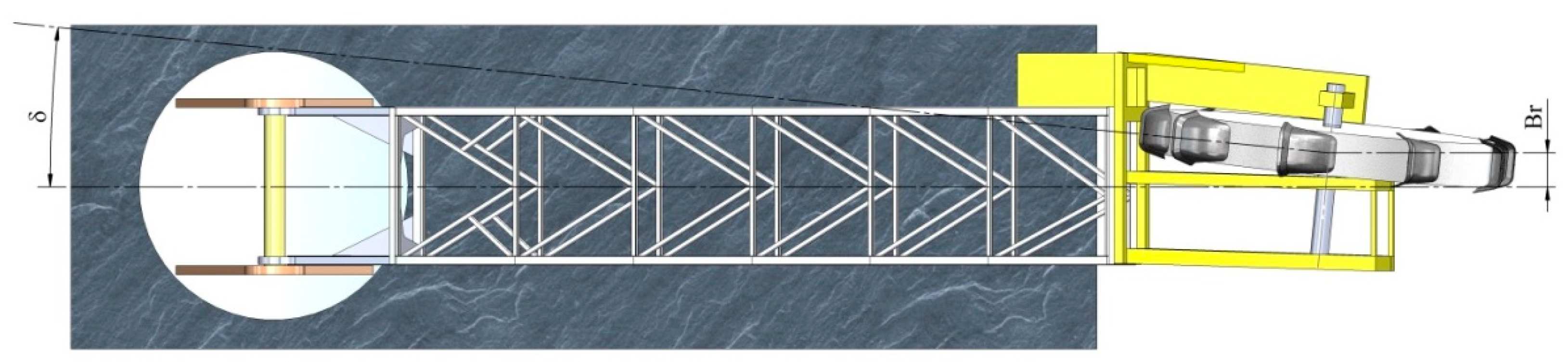
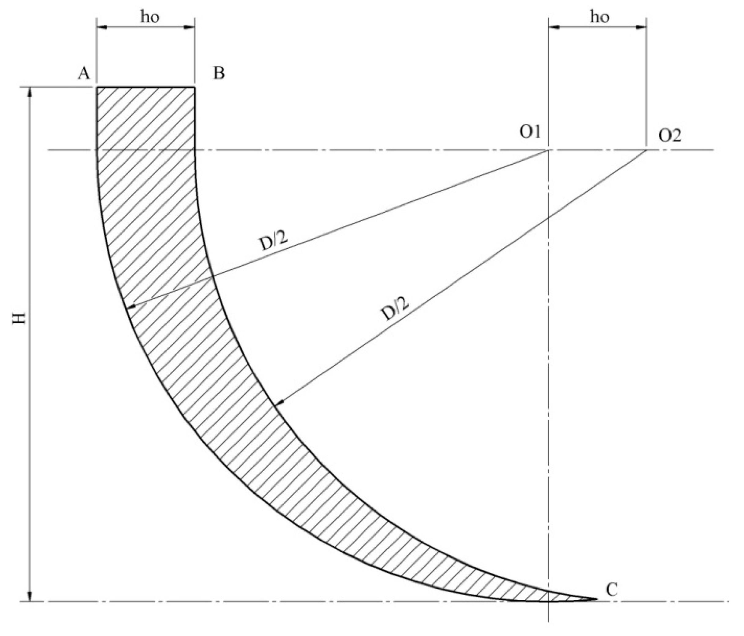
The main geometric characteristics that determine the dimensions of the extracted slices are shown in
Figure 6 and
Figure 7. Thus, in
Figure 6, D is the cutting diameter of the bucket wheel, R
p is the slewing radius, γ is the tilt angle of the arm in the vertical plane, L
s is the length of the arm, H
s is the height of the rotation axis of the arm from the level of the berm’s floor, H
sp is the distance between the center of rotation of the bucket wheel and the lower plane of the arm.
In
Figure 7, B
r is the distance between the bucket wheel center of rotation and the vertical arm symmetry plane, and
δ is the angle between the longitudinal axis of the bucket wheel and the arm pivot axis.
5. Results and Discussions
As shown, the volume of the slice model was determined for excavation heights ranging from 3.5 to 7.5 m, with a step of 0.2 m. The resulting values are presented in
Table 3. The calculation of excavation energy and the corresponding power was made for each volume, taking into account three specific excavation energy values. The three values correspond to the ends and middle of their variation range. The overall efficiency of the excavator’s bucket wheel drive system is 80%. Thus, the power values at the drive engine axis are those shown in
Table 3.
In
Figure 16, we presented the change in power according to height
H for the three specific excavation energy values, regression lines, and their corresponding equations as well as the constant value of the nominal power
Pn of the bucket wheel actuating engine.
The power variation is approximately linear. As expected, for all specific energy values, the power increases with the increase in the height
H of excavation. The analysis of the diagrams in
Figure 16 shows that for the maximum value of the specific energy considered, the power required by the excavation process exceeds the nominal engine power for a value of height
H in the range of 5.5–6.5 m. The equation of the regression line (
Figure 16) corresponding to this situation is:
Based on Equation (19), for a power equal to the nominal power value of the engine Pn = 630 kW, we determined the value of height Hmax for the imposed cutting parameters and for the slewing cycle time of the boom. The value of this height is Hmax = 5.68 m
Safe operation of the bucket wheel engine requires that the maximum excavation power be less than its rated power. Under these conditions, it is necessary to determine the slewing time so that the excavation power will not exceed the rated power of the engine according to the following relationship:
Based on this relationship (20), the resulting value of the minimum slewing time for the analyzed excavation conditions is Tmin = 585 s. Achieving an excavation time greater than or equal to Tmin assumes a lower slewing speed than m/s.
6. Conclusions
The actuating power requirement of the BWE drive was derived using the specific cutting energy issued from the measured cutting force on a measuring rig, from samples collected from open pit mines, through measurement of the slewing time of an operating excavator, and the excavated volume of a slice obtained by numerical modeling.
In this respect, the basic laws and principles of mechanical rock cutting using tooth are reviewed and presented in a suitable approach.
Accordingly, a method is proposed for the estimation of the load of the bucket wheel drive motor, by taking into account only the specific energy for the cutting of the material, the excavated volume at one slewing, and the time required to excavate this volume.
This method is used for establishing the correlation between the height of the excavated slice and the slewing speed of the boom, and correcting the slewing time so that the excavation power does not exceed the rated power of the engine.
Three values for specific energy determined on samples using a test rig, namely 0.15, 0.22, and 0.27 kWh/m3, were used for the calculation of the total energy and power for the excavation of one slice, with different values for the bench height H, between 3.5 m (the minimal rational value for excavation with BWEs) and 7.5 m (about 2/3 of the bucket wheel diameter, the maximum possible, from the perspective of slope stability).
The obtained power values are in the range of 157 kW–847 kW; their regression lines are plotted as a function of height, with specific energy as a parameter. The values were compared with the nominal power of the bucket wheel drive. For the first two values of the specific energy, the power is below the nominal value for the entire range of the working height, and in case of the maximum value, it exceeds the nominal value at a height of 5.68 m. For safe excavation in this kind of rock, the slewing time for height exceeding this value must be extended (slewing speed reduced) by about 25%.
The obtained results are useful for the optimization of the bucket wheel drive power and thus improve energy efficiency, increase the performance of excavators, and reduce operating costs.


 ,
, 


