Article

Performance Optimization of Solar-Assisted Heat Pump System for Water Heating Applications

1
CSIR—Central Building Research Institute, Roorkee 247667, India
2
Academy of Scientific and Innovative Research (AcSIR), Ghaziabad 201002, India
3
Thapar Institute of Engineering and Technology, Patiala 147001, India
4
College of Engineering, Mathematics and Physical Sciences, Renewable Energy, University of Exeter, Penryn, Cornwall TR10 9FE, UK
*
Authors to whom correspondence should be addressed.
Energies 2021, 14(12), 3534; https://doi.org/10.3390/en14123534
Submission received: 23 April 2021 / Revised: 5 June 2021 / Accepted: 10 June 2021 / Published: 14 June 2021

Abstract

:
The use of solar energy in water heating applications, such as in solar-assisted heat pump systems, has great benefits, such as reductions in heat transfer losses, control over incident solar heat, and generation of environmentally benign water heat. In the present study, we performed parametric optimization based on an experimental model of a solar-assisted heat pump system for water heating (SAHPSWH) in the context of colder climatic regions receiving minimal solar radiation. Various parameters were investigated, such as the different glazing arrangements, the distances between fluid-circulating tubes, and the absorber sheet arrangement. The results showed that double glazing was more efficient than single glazing, with average COP values of 3.37 and 2.69, respectively, and with similar heat gain rates. When the evaporator tube was soldered below the absorber plate, the COP was 1.19 times greater than when the tube was soldered above the absorber plate. We also analyzed whether the collector efficiency factor F′ has an inverse relationship with the tube distance and a direct relationship with the absorber plate thickness. Through this experimental study, we verified that the SAHPSWH is reliable if designed judiciously. This promising energy-saving system is particularly suitable for areas abundant in solar radiation, such as in India, where the needs for space conditioning and water heating are constant.

Graphical Abstract

1. Introduction

To construct energy-efficient sustainable buildings in compliance with the emerging regulations for global warming and greenhouse gas (GHG) emissions, several changes are required [1,2]. The use of renewable sources of energy to achieve this goal has largely been endorsed [3]. Among the renewable sources, solar energy is the most readily available source of clean energy, with minimal costs and environmental impacts [4]. Applications based on solar thermal energy have gained massive attention from 1970′s onwards, following the beginning of the energy crisis [5]. The process of collecting solar arrays in the form of energy and converting them into useful heat for water heating, space conditioning, or agricultural or industrial applications is the basis of solar thermal applications [6]. Solar water heating accounts for a major proportion of all applications in the market; however, various technical flaws, such as uncertainty related to the heat gain efficiency and heat loss, act as barriers to its promotion [7]. The integration of heat pumps for thermal applications can potentially rectify such issues [8]. The solar-assisted heat pump system for water heating (SAHPSWH) has advantages over conventional solar water heaters in terms of performance and initial investment, even under changing conditions and uneven weather. The conventional systems contain water as the working fluid, while hybrid water heating systems use a refrigerant as the working fluid, which transfers heat to the water [9]. The SAHPSWH solves the common issues of conventional systems regarding the high investment costs for collector components and the problems that arise due to corrosion. In contrast, the SAHPSWH is able to work under moderate climatic conditions with solar radiation, enhancing the energy efficiency of buildings [10]. A plethora of research studies have experimentally and numerically [11] evaluated the potential of solar thermal hot water collectors and their combination with heat pumps to reduce site energy consumption in heating applications.
Jose et al. analyzed a SAHPSWH experimentally for sub-zero temperature conditions and observed a COP value of 3.01 when heating 300 L from 14 to 55 °C at an ambient temperature of 21.9 °C over 638 min, along with observing a transient increase in the heating process during the first 15 min before reaching a trans-steady-state [12]. A study based on an economic comparison between a SAHPSWH and a conventional system for tropical and sub-tropical regions showed decreased annual operating costs, with a notable payback time and the need for different configurations based on climatic variations [13].
By modifying solar collectors with corrugated metal roofing and a copper tube, along with a compressor speed of 20 rps and mass flow rate of 0.01 kg/s, the COP values obtained were between 2.5 and 5.0. The suitable mass for the storage tank was 400 kg with a payback time of 2.3 years [14]. A combined SAHPSWH with serial and parallel modes was experimentally and numerically validated, with the results suggesting the use of the serial mode in winter and parallel mode in summer, with an annual average COP of 5.7 [15]. A numerical study validated the performance of the SAHPSWH under frosting conditions, showing reliable heating performance with an average COP of 2.75 and delayed frost formation in comparison with a traditional system. This clearly showed that with decreased ambient temperature and increased solar radiation intensity, frost formation can be prohibited [16].
In [17], an experimental setup involving a SAHPSWH was structured for the purpose of both water and space heating, resulting in a COP of 2.1 for water heating and an average COP of 2.5 for space heating under variable climate conditions. Tagliafico et al. [18] showed the SAHPSWH approach to be very efficient, even for uneven weather conditions, proving the approach to be environmentally friendlier than a traditional solar heater integrated into a gas burner. The average savings in energy consumption based on different glazing configurations were also analyzed.
Cutic et al. [19] determined that COP levels are significantly altered by alterations in solar radiation based on convection theory, enabling the absorption of heat due to higher ambient temperatures and lower evaporation temperatures. Bastos et al. [20] studied the SAHPSWH prototype for the purpose of heating residential water via numerical simulations and experimental validation, proving that the power consumed by the compressor varied due to radiation and wind speed. Additionally, a decrease was observed in the COP because of a pressure loss in the evaporator and due to the compressor not being thermally insulated.
Buker and Riffat [21] studied a system in which solar thermal collectors were combined with heat pumps in a single SAHPSWH, which can be used for various purposes. They reviewed various systems from the past and present using visualizations, systematic representations, and component classification. They experienced challenges in classifying the systems based on a variety of parameters, configurations, and performance criteria, which increased the level of complexity. Additionally, they found that there were separate effects of solar heat energy on the collector efficiency and heat pump, concluding that the SAHPSWH has great potential and could be an alternative for various purposes and different climatic zones around the world.
Chaturvedi et al. [22] studied a sustainable SAHPSWH for low-temperature water heating applications, analyzing the energy savings and economic feasibility of the system. The thermal performance of the system was simulated with the help of computer software, which embedded location-based irradiation, collector, heat pump, and other data. The economic feasibility was checked with the help of the life cycle cost (LCC) method. It was found that the direct expansion approach of the SAHPSWH when compared with a conventional electric water heater was economical, conserving energy by 60%. This system can fulfill the demands of low-temperature water heating applications.
From the above studies, it can be inferred that the SAHPSWH is a good alternative for various climatic zones around the world in terms of cost-effectiveness and energy conservation. The COP values for the system vary with different structural arrangements or with variations in solar radiation intensity and ambient temperature. The economic analysis conducted for the system both numerically and experimentally validated its proficiency, showing that different meteorological conditions require specific configurations to achieve better performance. Although several studies have been presented in this review, the full range of applications of this technology is still to be shown, since laboratory-based experiments and real-world conditions are different. This study represents one such real-world scenario, involving different optimization strategies. To the best of our knowledge, as highlighted in the literature, there is no evidence of experimental optimization based on permutations and combinations of tube arrangements and different glazing layers for a composite climate. In this study, an experimental effort is made to optimize the design parameters and identify the best design strategies that may help in reducing the complexity while classifying the system.
An experimental study is performed in a composite climate in India at 29.8543° N, 77.8880° E, during the winter season, with an average temperature range of 15–20 °C. This is done in order to tune the conditions to the colder climatic zone of India, so that the results of this study can be used by designers for colder climates. With the help of mathematical modeling, the system components are designed. The SAHPSWH is essentially designed for domestic applications, but with further exploration could be used for commercial applications. The experiment is conducted in an ingenious manner by using a multiobjective optimization approach, resulting in different seasonal arrangements with certain permutations and combinations. Minute effects of plate and tube arrangements in accordance with suitable weather are observed. An extensive glazing and tube arrangement study is performed in the present experiments. Firstly, the effects of different configurations of evaporator tubes on the collector performance are evaluated, while simultaneously the effects of glazing on the overall performance of the system are observed, showing that this technology is sustainable for water heating applications.
The remainder of the paper is as follows. Section 2 describes the case study and methodology employed for the experiment. Section 3 provides insights into the experimental setup and instruments used. Section 4 presents the results of the experimental investigation, while the last section provides concluding remarks.

2. Methodology

The solar water heater’s performance can be enhanced either by reducing the top heat loss or by improving the convective heat transfer coefficients by changing the working fluid and extracting that heat via a heat exchanger. In this study, the primary concern was the enhancement of the thermal performance of the SAHPSWH. The effects of different parameters, such as the configuration of the collector tubes, glazing material, ambient conditions, and solar intensity on the flat plate collector efficiency, were assessed to expand its commercial applications. An experimental setup was constructed as shown in Figure 1, in which necessary parameters and component specifications, such as the absorber plate thickness, the distance between the collector tubes, and tube diameter, were first optimized using mathematical models, along with climatic variations measured by various measurement devices. The experiment was performed in a composite climate in India in a low-cost bamboo house to completely replicate the winter climatic conditions in the country, which was then supported by theoretical analysis. The readings during the experiment were taken at five-minute intervals.

2.1. Mathematical Modeling

For the prediction of the thermal performance, a 1-D mathematical model was built to predict the thermal performance, which was grounded on certain assumptions:
  • The system is at a quasi-steady state within the chosen time interval;
  • Negligible pressure drops occur in the evaporator, condenser, and piping;
  • Both at the exits of the condenser and the evaporator, the refrigerant is considered to be saturated;
  • Compression of the refrigerant vapor is assumed to follow a polytropic process;
  • Expansion of the refrigerant liquid is considered to be isenthalpic;
  • The hot water storage tank is assumed to be non-stratified [23,24,25,26,27,28,29].

2.2. Thermal Performance of the Glazed Flat Plate Collector

Various operational and design variables influence the performance of solar collectors. The useful heat gain of the collector (Qu) can be evaluated using three governing parameters: the collector efficiency factor F′, the overall heat loss coefficient UL, and the effective transmittance–absorptance product of the cover system (τα). Under steady-state conditions, when tubes are placed above the operating absorber plate, the Qu of a glazed collector can be evaluated as [30]:
Q u = F A c τ α I T U L T e T a
UL is primarily due to the convection and radiation heat transfer from the top surface of the collector to the surroundings. UL can be evaluated as follows:
U L = U b + U t + U e
The bottom heat loss and edge heat loss are both assumed to be negligible. The top loss coefficient can be computed with the help of an empirical equation derived by Klein [31]:
U t = M C T P T P T a M + f e + 1 h w 1 + σ T P 2 + T a 2 T P + T a ε p + 0.059 Mh w 1 + 2 M + f 1 + 0.133 ε p ε g M
where:
  f = 1 + 0.089 h w 0.116 h w ε p 1 + 0.07866 M
e = 0.43 1 100 T P
and:
C = 520 1 0.000051 β 2   for   0 < β < 70 ° ;   use   β = 70 °   when   70 ° < β < 90 °
For the single-glazed flat plate collector, M = 1, while for the double-glazed flat plate collector, M = 2.
The convection heat transfer coefficient, hw, for the outer glass cover is determined regarding the wind velocity V on the collector surface by the following formulae in cases where the forced flow convection prevails:
h w = 5.7 + 3.8 V
A. Tubes soldered above the absorber plate
When tubes are soldered above the absorber plate, the following expression developed by Hottel–Whilliar–Bliss is used to determine F′ [32]:
F = 1 WU L π D o h fi + 1 D o W + 1 WU L C bond + W W D o F
where,
F = tan h m W D o / 2 m W D o / 2
and
m = U L / k p δ p
B. Tubes soldered below the absorber plate
When tubes are soldered below the absorber plate, F′ can be evaluated by using the following expression developed by Hottel–Whilliar–Bliss [33,34]
F = 1 U L W 1 U L D o + W D o F + 1 C b + 1 π D i h fi
F = tan h m W D o / 2 m W D o / 2
m = U L / k p δ p
The refrigerant mass flow rate can be determined from the volumetric efficiency of the compressor by using the equations derived by Huang and Chyng [35]:
m ˙ r = η ν × V D ν
where:
η ν = 0.0163 × P 2 P 1 + 0.6563
The efficiency of the flat plate collector is as follows:
η = Q u A c I T
C. Coefficient of Performance (COP) of the SAHPWSH System
The performance of the hybrid model can be determined by its coefficient of performance.
The COP of the heat pump can be evaluated as:
COP = Themal   energy   rejected   by   the   condensor Energy   input   to   the   compressor
COP = Q c W comp

3. Experimental Setup and Instrumentation

The SAHPSWH shown in Figure 2 is a configuration that directly uses the solar collector in place of the evaporator in the cycle to reduce inefficient thermodynamic processes across eliminated components. Based on different studies and the present observations, the SAHPSWH has several advantages, which were attributed to the plate thickness being in the range of 1–5 mm, resulting in a significant increase in the COP by 0.5% but with no further increases found after 5 mm. Copper and aluminium are regarded as ideal materials for manufacturing solar collectors, as they have good K values and high ductility. Using R-134a as the refrigerant in the system can result in COP values at least 15% higher than those obtained using refrigerant mixtures (R-404a, R-407c, and R-410a). The critical design properties of the refrigerant allowing satisfactory system performance are the high thermal conductivity, evaporation enthalpy, and critical temperature. R-134a leads to minimum corrosion problems; thus, its life is typically ten times that of the collector carrying water as a fluid. The very low freezing point of the refrigerant can be advantageous in experiments. By eliminating the intermediate exchanger required in the conventional system, this improves the thermal performance of the SAHPSWH. The system uses a solar collector for the evaporator–compressor to increase the system performance, using a condenser as the heat transfer unit and a capillary as the expansion device, with the following specifications for the main components.
Collector: In the study, we used a flat plate collector measuring 1.83 m (L) × 1.22 m (W) × 0.1 m (T) with transparent glazing as a cover on the top of a 0.3-mm-thick dark copper plate absorber incorporated in an extruded aluminum collector box. Different types of glazing were utilized to minimalize the heat from the absorber plate top. Fiberglass wool was used as insulation to minimize the heat loss from the bottom and side of the collector, along with an insulation cover for the probable exposure area responsible for the occurrence of heat loss. Solar radiation passes through the transparent glazing on the absorber plate over a 2.1 m2 ±   0.1 m2 absorbing area. The heat absorbed is then transferred to the R-134a refrigerant flowing in the tubes, with inner and outer diameters of 7.8 and 8.5 mm, respectively, brazed with an absorber plate. These absorber plates were layered with selective black chrome paint to absorb maximum radiation.
Compressor: A reciprocating hermetically sealed compressor with an input power of 245 W and a flow rate of 5.79 cc/rev was incorporated, working on the basic principle of increasing the pressure of the refrigerant by reducing the volume of the fluid. The compressor increases the refrigerant pressure, which significantly contributes towards increases in the refrigerant temperature.
Capillary: An optimized 0.91-mm-diameter copper capillary with a length of 3.048 m was used in the construction. Two parallel 1.52 mm capillaries were used with a copper filter. Before entering the evaporator again, it became necessary to normalize the temperature and pressure of the refrigerant. Therefore, after losing latent heat, a reduction in pressure can be achieved via the diffusion action within the capillary, thereby increasing the volume of the refrigerant fluid, leading to a decrease in the pressure amongst the refrigerant.
Condenser: The condenser was used here to transfer heat to the water. The main function of a condenser is to condense a refrigerant from its gaseous state to a liquid state, after which its latent heat is moved to the storage tank. The condenser consisted of copper tubes with an outer diameter (9.525 mm) and length of 9.75 m immersed in the storage tank, which was assumed to be non-stratified, i.e., losses can be neglected while determining the coefficient of performance.
Instrumentation/Measuring Devices: The apparatus was in the appropriate arrangement to evaluate the system performance under different conditions. The measuring devices used to collect the necessary data were a 4-channel SZ-7504 temperature scanner, a SZ-7569-P temperature scanner, a pressure gauge, a pyranometer, an anemometer, a sling psychrometer, an energy meter, a voltmeter, and an ammeter, with a differential pressure switch as a safety device. To calculate the COP of the system, temperature readings were taken from 4 points, namely at the inlet of the evaporator–collector, the outlet of the evaporator–collector, the discharge port of the compressor, and the condenser outlet using type 1 and type 2 thermocouples. Table 1 shows the measuring devices with their measurement and uncertainty ranges.

4. Results and Discussion

Experiments with different sheet and tube arrangements in the flat plate collector of the SAHPSWH with single-glazed and double-glazed evaporators were conducted under different conditions. The effects of the tank temperature and evaporation temperature on the COP of the hybrid system, of the heat transfer rate across the condenser, of solar radiation on the tank temperature, and of the various parameters of the solar flat plate collector were investigated.

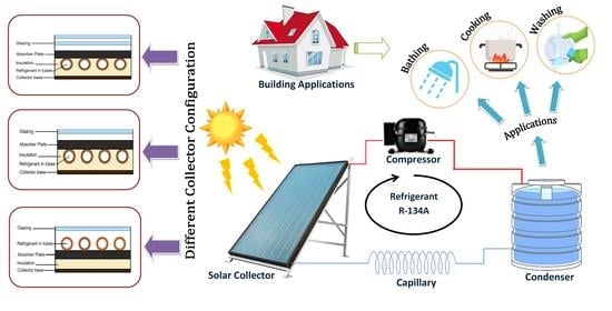
4.1. Effects of Different Tube Configurations

The nomenclature for the absorber plate and tube used for the experimental study is shown in Figure 3, where Di is the internal diameter of the tube, Do is the external diameter of the tube, b represents the bond width between the serpentine tube and the absorber plate with thickness δ, and δt is the thickness of the serpentine tube used.
Geometrical and physical data for the tubes obtained from the mathematical modelling for the optimization of the SAHPWHS are represented in Table 2.
The following two cases were considered to evaluate the effects of different tube configurations on the solar plate collector. Case 1: In this case, the evaporator tubes were soldered above the absorber plate, with the cross-section area of the serpentine tubes shown in Figure 4a. Case 2: In this case, the evaporator tubes were soldered beneath the absorber plate SAHPSWH, with the cross-section area of the serpentine tubes shown in Figure 4b.
The experiment was performed in a cold climate after establishing steady-state conditions with varying solar intensities on different days and with variations in ambient temperatures. The data recordings for solar intensity were carried out at 30 min intervals for the two cases, which were almost the same as observed in Figure 5.
The thickness of the absorber plate and pitch W (center-to-center distance of tubes) were mathematically computed for economical optimization of the experiment, as a low value of W will result in an increased length and a higher δ value will increase the material cost. Additionally, the F′ value was observed to be strongly influenced by W and δ in Figure 6a,b, as F′ increased with an increase in the thickness of the absorber plate and correspondingly decreased with an increase in the W value; therefore, the optimal pitch and thickness for absorber plate for the experiment were 0.1 and 0.003 m, respectively.
The effect of the efficiency of the collector (η) on the F′ (Figure 7) resembled the prominence of the collector tube arrangement, i.e., when placed below the absorber plate, η values ranged from 46% to 58%, with variations in F′ ranging between 0.75 and 0.83, while η values ranged from 60% to 75% when the tubes were placed above the absorber plate, with varying F′ values ranging from 0.91 to 0.95.
Figure 8a depicts the increases in evaporator temperature with increasing solar radiation. Increases in evaporator temperature also increased the performance of the SAHPSWH.
Figure 8b shows the effects of the evaporator temperature on the condenser temperature, showing that with the increases in evaporator temperature, the working fluid condensing temperature also increased. Nevertheless, the effects of the solar radiation on the evaporator temperature were greater than that of the condenser temperature. When solar radiation started decreasing, the evaporator temperature decreased irrespective of the condensing temperature, showing that at a higher temperature, evaporation takes place in the system, which in turn improves the performance of the system.
The evaporator temperature is not allowed to exceed a certain value, as the compressor may get damaged when pushed beyond its operating limits. In the case of the below tube arrangement, the evaporation temperature may have been equal to ambient temperature; hence, better performance for the SAHPSWH was achieved as compared to the above tube arrangement shown in Figure 9.
An increase in COP with the increasing evaporation temperature due to its higher heat transfer rate than condenser can be observed in Figure 10. The relations between the collector efficiency factor (F′) and collector efficiency (η) for different sheet and tube arrangements are presented in Table 3, which shows that the efficiency of the below tube arrangement was better than the above tube evaporator arrangement.

4.2. Effect of Different Glazing

Experiments were performed with a single-glazed flat plate collector and a double-glazed flat plate collector, as shown in Figure 11a,b.
Figure 12 presents the increases in storage tank temperature with increasing evaporation temperature. With a limited compressor capacity temperature, the evaporator is not allowed to exceed a certain limit. According to the performance characteristic analysis for the single-glazed evaporator, the evaporation temperature could not surpass 23.1 °C, which is near ambient temperature; however, for the double-glazed evaporator, it exceeded the ambient temperature of 36.7 °C, achieving better performance for the heat pump.
For single glazing, the evaporation temperature range was 5.9–22.6 °C and the maximum heat gain was 0.0696 kWh, while for double glazing, the evaporation temperature range was 30.5–36.7 °C and the maximum heat gain was 0.104 kWh. If we compare both cases, due to high evaporation temperature, greater heat gain was found with double glazing. Therefore, double glazing results in better performance than single glazing. This also shows that the heat pump with the double-glazed evaporator produced higher evaporation temperatures and greater heat gain at the condenser than the single-glazed evaporator, resulting in better performance.
Figure 13 shows the effects of the evaporation temperature on COP. With an increase in solar radiation, the evaporation temperature also increases. The condensation rate, i.e., Qw, increases with higher evaporation temperatures and the difference between the inlet and outlet reservoir temperatures also decreases; thus, the heat pump COP increases with increasing evaporation temperatures. The maximum COP value for the heat pump in the case of a single-glazed evaporator was 5.2, while in the case of the double-glazed evaporator, the maximum COP values reached 6.96; hence, it has been shown in the figures that the SAHPSWH with the double-glazed evaporator provides better COP values than the single-glazed evaporator.
Figure 14a shows the variations of the water tank temperature with solar radiation during the period of the experiments. As the radiation values increase, the evaporator temperatures also increase, meaning the heat transfer rate at the condenser also increases, due to which the water tank temperature increases. Figure 14b shows the evaporation temperature variation with solar radiation during the period of the experiments. It was already mentioned that as the radiation values increase, the evaporation temperatures also increase.
It can be observed from Figure 15 that the performance of the collector can be approximated by measuring the solar intensity (IT), fluid inlet temperature (Tin), and ambient air temperature (Ta), as the efficiency of the system becomes a linear function if FR, τ, α, and UL are assumed to be constant for a particular flow rate and collector. Figure 16 shows that the collector efficiency highly depends on the collector’s heat removal factor. The slope of the line ( – FR UL) in Figure 17 represents the rate of heat loss, which is lower in this case as compared to the single glazing arrangement.
Figure 17 shows that the overall heat loss coefficient has a linear relationship with solar intensity, but for double glazing the overall heat loss coefficient is comparatively lower than for single glazing because the top heat loss coefficient is reduced as the number of glazing layers increases. Figure 18 shows the variation of solar radiation with time during the period of the experiments. There is no difference between the solar radiation in both cases. Table 4 shows the overall results of the experiments, depicting higher COP values when evaporator tubes are placed below the absorber plate with a double glazing arrangement.

5. Conclusions

This study was undertaken to examine the performance of the SAHPSWH and to find the best sheet and tube arrangement for flat plate collectors in colder climates of India. The experiment was performed in a composite climate during winter months. The tilt angle of the solar collector was 50° during the experiment. The key conclusions are listed as follows:
  • The results showed that 30 L of water could be heated from 23 °C to 50 °C in 55 to 75 min when evaporator tubes were soldered above the absorber plate, with energy consumption rates of about 0.30 to 0.39 kWh and with COP values varying between 2.17 and 2.47;
  • When evaporator tubes were soldered below the absorber plate, water was heated from 23 °C to 50 °C in 55 to 85 min, while the energy consumption ranged from 0.18 to 0.29 kWh and the COP values of the system ranged from 3.12 to 3.91;
  • It is evident that for both cases, the heat gain was almost same, while the maximum COP was achieved in the second case. This result clearly shows that the performance of the system with the below tube arrangement was better than the above tube arrangement;
  • The flat plate collector efficiency ranged from 46% to 58% when the tubes were placed below the absorber plate, with F′ values ranging between 0.75 to 0.83. The efficiency ranged between 60% and 75% when the tubes were placed above the absorber plate, with F′ values ranging from 0.91 to 0.95;
  • The efficiency factor of the collector (F′) directly affects the efficiency of the solar flat plate collector (η), which is influenced by two parameters, namely the center-to-center distance of the absorber tubes W and the absorber plate thickness δ. The tube distance W had a strong influence on F′, which resulted in a decrease in F′ with an increase in W. Consequently, by increasing the thickness of the absorber plate, a significant increase in F′ was observed;
  • For different glazing arrangements, the results showed that in the SAHPSWH, 30 L of water could be heated from 20 to 50 °C in 95–110 min with single glazing and with energy consumption of about 0.35 to 0.43 kWh and with COP ranging from 2.26 to 2.98. In the second case, the SAHPSWH with the double-glazed flat plate collector heated 30 L of water in the morning session from 20 to 50 °C in about 55–90 min, with energy consumption of about 0.25 to 0.34 kWh and with COP values ranging from 2.86 to 3.89. For both cases, the energy gain was almost same. This result clearly shows that the system performance with the double-glazed flat plate collector was better than with the single-glazed flat plate collector in the SAHPSWH;
  • The collector efficiency is strongly influenced by the parameter (Ti–Ta)/IT; if this parameter increases then collector efficiency decreases, because the slope of this line – (FR UL) represents the rate of heat loss from the collector. This slope decreased as the number of glazing layers increased from zero to three.
The SAHPSWH model in this study showed the best energy savings and has applicability for variable weather conditions. This is especially important for regions with a composite climate such as India, where space conditioning and water heating are required year-round. The present study has verified that the SAHPSWH is very reliable if it is carefully designed.

Author Contributions

Conceptualization, C.S.M.; methodology, C.S.M.; validation, C.S.M.; formal analysis, B.P.R., L.S., and N.A.; investigation, C.S.M., B.P.R., L.S., and N.A.; resources, C.S.M.; data curation, B.P.R., L.S., and N.A.; writing—original draft preparation, C.S.M.; writing—review and editing, C.S.M., B.P.R., L.S., N.A. and A.G.; visualization, B.P.R. and C.S.M.; supervision, C.S.M.; funding acquisition, C.S.M. and A.G. All authors have read and agreed to the published version of the manuscript.

Funding

This research received no external funding.

Data Availability Statement

The data are not publicly available due to privacy considerations.

Acknowledgements

The paper is submitted for publication with the permission of the Director, CSIR-Central Building Research Institute, Roorkee.

Conflicts of Interest

The authors declare no conflict of interest.

Nomenclature

SymbolNomenclatureUnit
cSpecific heat capacityJkg−1K−1
MNumber of covers-
COPCoefficient of performance-
AcArea of collectorm2
hwWind heat transfer coefficientWm−2K−1
ITIncident solar radiation on the collectorWm−2
KPThermal conductivity of absorber plateWm−1K−1
QuUseful heat gain by collectorW
TaAmbient temperature
TPThe temperature of the absorber plate
ULOverall heat loss coefficientWm−2C−1
UtTop loss coefficientWm−1K−1
UbBottom loss coefficientWm−1K−1
UeEdge loss coefficientWm−1K−1
VWind velocityms−1
F′Collector efficiency factor-
TeEvaporator temperature
ε p Emissivity of absorber plate-
ε g Emissivity of glass cover-
βInclination angle of collector°
WPitch of tubesm
bWidth of bondm
DoTube outside diameterm
DiTube inside diameterm
hfiInlet fluid heat transfer coefficientWm−2K−1
CbondBond conductancemKW−1
FFin efficiency -
δ p Thickness of absorber platem
m ˙ r Mass flow rate of the refrigerant (R-134a)Kgs−1
η ν Volumetric efficiency of the collector-
P2Pressure at the outlet of compressor–inlet of condenserKgs−1
P1Pressure at the inlet of compressor–exit of evaporatorKgs−1
η Efficiency -

References

  1. Aggarwal, V.; Meena, C.S.; Kumar, A.; Alam, T.; Kumar, A.; Ghosh, A.; Ghosh, A. Potential and future prospects of geothermal energy in space conditioning of buildings: India and worldwide review. Sustainability 2020, 12, 8428. [Google Scholar] [CrossRef]
  2. Agarwal, N.; Meena, C.S.; Raj, B.P.; Saini, L.; Kumar, A.; Gopalakrishnan, N.; Kumar, A.; Balam, N.B.; Alam, T.; Kapoor, N.R.; et al. Indoor Air Quality Improvement in COVID-19 Pandemic: Review. Sustain. Cities Soc. 2021, 70, 102942. [Google Scholar] [CrossRef] [PubMed]
  3. Zeng, R.; Wang, X.; Di, H.; Jiang, F.; Zhang, Y. New concepts and approach for developing energy efficient buildings: Ideal specific heat for building internal thermal mass. Energy Build. 2011, 43, 1081–1090. [Google Scholar] [CrossRef]
  4. Bellos, E.; Tzivanidis, C.; Moschos, K.; Antonopoulos, K.A. Energetic and financial evaluation of solar assisted heat pump space heating systems. Energy Convers. Manag. 2016, 120, 306–319. [Google Scholar] [CrossRef]
  5. Huang, Y.; Niu, J.; Chung, T. Study on performance of energy-efficient retrofitting measures on commercial building external walls in cooling-dominant cities. Appl. Energy 2013, 103, 97–108. [Google Scholar] [CrossRef]
  6. Tzivanidis, C.; Bellos, E.; Mitsopoulos, G.; Antonopoulos, K.A.; Delis, A. Energetic and financial evaluation of a solar assisted heat pump heating system with other usual heating systems in Athens. Appl. Therm. Eng. 2016, 106, 87–97. [Google Scholar] [CrossRef]
  7. Nozik, A.J. Photoelectrochemistry: Applications to Solar Energy Conversion. Ann. Rev. Phys. Chem. 2003, 29, 189–222. [Google Scholar] [CrossRef]
  8. Lewis, N.S. Toward cost-effective solar energy use. Science 2007, 315, 798–801. [Google Scholar] [CrossRef] [Green Version]
  9. Li, B. Integration of Solar Systems with Heat Pumps and Other Technologies. In Handbook of Energy Systems in Green Buildings; Wang, R., Zhai, X., Eds.; Springer: Berlin/Heidelberg, Germany, 2017; pp. 1372–1407. [Google Scholar]
  10. Tagliafico, L.A.; Scarpa, F.; Valsuani, F. Direct Expansion Solar-Assisted Heat Pumps—A Clean Steady State Approach for Overall Performnace Analysis. Appl. Therm. Eng. 2014, 66, 216–226. [Google Scholar] [CrossRef]
  11. Alam, T.; Meena, C.S.; Balam, N.B.; Kumar, A.; Cozzolino, R. Thermo-Hydraulic Performance Characteristics and Optimization of Protrusion Rib Roughness in Solar Air Heater. Energies 2021, 14, 3159. [Google Scholar] [CrossRef]
  12. Fernández-seara, J.; Piñeiro, C.; Dopazo, J.A.; Fernandes, F.; Sousa, P.X.B. Experimental analysis of a direct expansion solar assisted heat pump with integral storage tank for domestic water heating under zero solar radiation conditions. Energy Convers. Manag. 2012, 59, 1–8. [Google Scholar] [CrossRef]
  13. Li, Y.; Kao, W. Performance analysis and economic assessment of solar thermal and heat pump combisystems for subtropical and tropical region. Sol. Energy 2017, 153, 301–316. [Google Scholar] [CrossRef]
  14. Nuntaphan, A.; Chansena, C.; Kiatsiriroat, T. Performance analysis of solar water heater combined with heat pump using refrigerant mixture. Appl. Energy 2009, 86, 748–756. [Google Scholar] [CrossRef]
  15. Huan, C.; Li, S.; Wang, F.; Liu, L.; Zhao, Y.; Wang, Z.; Tao, P. Performance Analysis of a Combined Solar-Assisted Heat Pump Heating System in Xi’an, China. Energies 2019, 12, 2515. [Google Scholar] [CrossRef] [Green Version]
  16. Kong, X.; Li, J.; Wang, B.; Li, Y. Numerical study of a direct-expansion solar-assisted heat pump water heater under frosting conditions based on experiments. Sol. Energy 2020, 196, 10–21. [Google Scholar] [CrossRef]
  17. Cutic, T.; Pasanec, J.; Baleta, J.; Soldo, V.; Curko, T. Mobile Solar-Assisted Heat Pump with Direct Expansion. In Proceedings of the EuroSun 2012—ISES Europe Solar Conference, Rijeka, Croatia, 18–20 September 2012. [Google Scholar]
  18. Bastos, H.M.C.; Torres, P.J.G.; Álvarez, C.E.C. Numerical simulation and experimental validation of a solar-assisted heat pump system for heating residential water. Int. J. Refrig. 2018, 86, 28–39. [Google Scholar] [CrossRef]
  19. Buker, M.S.; Riffat, S.B. Solar assisted heat pump systems for low temperature water heating applications: A systematic review. Renew. Sustain. Energy Rev. 2016, 55, 399–413. [Google Scholar] [CrossRef]
  20. Chaturvedi, S.K.; Abdel-Salam, T.M.; Sreedharan, S.S.; Gorozabel, F.B. Two-Stage Direct Expansion Solar-Assisted Heat Pump for High Temperature Applications. Appl. Therm. Eng. 2009, 29, 2093–2099. [Google Scholar] [CrossRef]
  21. Morrison, G.L. Simulation of Packaged Solar Heat Pump Water Heaters. Sol. Energy 1994, 53, 149–257. [Google Scholar] [CrossRef]
  22. Mehdaoui, F.; Hazami, M.; Naili, N.; Farhat, A. Energetic performances of an Optimized Passive Solar Heating Prototype used for Tunisian Buildings Air Heating Applications. Energy Convers. Manag. 2014, 87, 285–296. [Google Scholar] [CrossRef]
  23. Bridgeman, A.G. Experimental Analysis of an Indirect Solar Assisted Heat Pump for DomesticWater Heating. Ph.D. Thesis, Queen’s University, Kinsgton, ON, Canada, 2010. [Google Scholar]
  24. DeGrove, J.M. The Integration of Heat Resources in a Solar Thermal Heat Pump Hydronic System. Ph.D. Thesis, Purdue University, West Lafayette, IN, USA, 2015. [Google Scholar]
  25. Khalaf, K. Experimental Characterization and Modelling of a Heat Pump Water Heater. Ph.D. Thesis, Carleton University, Ottawa, ON, Canada, 2017. [Google Scholar]
  26. Fu, Y. Investigation of Solar Assisted Heat Pump System Integrated with High Rise Residential Building. Ph.D. Thesis, University of Nottingham, Nottingham, UK, 2014. [Google Scholar]
  27. Hu, Z.; Zhang, S.; Chu, W.; He, W.; Yu, C.; Yu, H. Numerical Analysis and Preliminary Experiment of a Solar Assisted Heat Pump Drying System for Chinese Wolfberry. Energies 2020, 13, 4306. [Google Scholar] [CrossRef]
  28. Valancius, R.; Singh, R.M.; Jurelionis, A.; Vaiciunas, J. A Review of Heat Pump Systems and Applications in Cold Climates: Evidence from Lithuania. Energies 2019, 12, 4331. [Google Scholar] [CrossRef] [Green Version]
  29. Zhao, Z.; Zhang, Y.; Mi, H.; Zhou, Y.; Zhang, Y. Experimental Research of a Water-Source Heat Pump Water Heater System. Energies 2018, 11, 1205. [Google Scholar] [CrossRef] [Green Version]
  30. Mohanraj, M.; Belyayev, Y.; Jayaraj, S.; Kaltayev, A. Research and developments on solar assisted compression heat pump systems–A comprehensive review (Part A: Modeling and modifications). Renew. Sustain. Energy Rev. 2018, 83, 90–123. [Google Scholar] [CrossRef]
  31. Thygesen, R. An Analysis of Different Solar-Assisted Heating Systems and Their Effect on the Energy Performance of Multifamily Buildings—A Swedish Case. Energies 2017, 10, 88. [Google Scholar] [CrossRef] [Green Version]
  32. Klein, S.A. Calculation of Flat Plate Collector Loss Coefficients. Sol. Energy 1975, 17, 79–80. [Google Scholar] [CrossRef]
  33. Duffie, J.A.; Beckman, W.A. Solar Engineering of Thermal Processes; John Wiley and Sons, Inc.: Hoboken, NJ, USA, 1991; pp. 164–165. [Google Scholar]
  34. Duffie, J.A.; Beckman, W.A. Solar Engineering of Thermal Processes; John Wiley and Sons, Inc.: Hoboken, NJ, USA, 1991; pp. 148–149. [Google Scholar]
  35. Chyng, J.P.; Lee, C.P.; Haung, B.J. Performance analysis of a solar-assisted heat pump water heater. Sol. Energy 2003, 74, 33–44. [Google Scholar] [CrossRef]
Figure 1. In-field experimental setup (location: 29.8543° N, 77.8880° E).
Energies 14 03534 g001
Figure 2. Schematic diagram of the SAHPSWH.
Energies 14 03534 g002
Figure 3. Nomenclature used for absorber plate and tube configuration.
Energies 14 03534 g003
Figure 4. Cross-sections of the serpentine tubes: (a) above the absorber plate; (b) below the absorber plate.
Energies 14 03534 g004
Figure 5. Solar intensity variations with time.
Energies 14 03534 g005
Figure 6. Collector efficiency factor variations due to different factors: (a) pitch of tubes; (b) absorber plate thickness.
Energies 14 03534 g006
Figure 7. Collector efficiency factor variations.
Energies 14 03534 g007
Figure 8. Effects of various factors on evaporator temperature: (a) solar radiation; (b) condenser temperature.
Energies 14 03534 g008
Figure 9. Variations in the temperature difference (Te–Ta) with time.
Energies 14 03534 g009
Figure 10. COP of the system with varying evaporator temperature.
Energies 14 03534 g010
Figure 11. Different evaporator setups: (a) single-glazed evaporator; (b) double-glazed evaporator.
Energies 14 03534 g011
Figure 12. Evaporator temperature variations with storage tank temperature.
Energies 14 03534 g012
Figure 13. Effects of evaporation temperature on COP.
Energies 14 03534 g013
Figure 14. Temperature variations due to solar radiation: (a) water tank temperature; (b) evaporator temperature.
Energies 14 03534 g014
Figure 15. Performance of a typical flat-plate solar collector.
Energies 14 03534 g015
Figure 16. Heat removal factor variations due to the efficiency of the collector.
Energies 14 03534 g016
Figure 17. Variations of the overall heat loss coefficient with solar intensity.
Energies 14 03534 g017
Figure 18. Solar radiation variation with time.
Energies 14 03534 g018
Table 1. Measuring devices with measurement range and uncertainty data.
Measuring Instrument Measurement Range Uncertainty
Type 1 thermocouple −50–99 °C±0.1 °C
Type 2 thermocouple−100–200 °C±0.1 °C
Pressure gauge (bourdon type)600–4000 mbar±1%
Pyranometer TBQ-20–2000 Wm−27–14 µV·W−1m2
Anemometer 0.9–0.35 m/s0.2–0.6%
Table 2. Geometrical and physical data for evaporator tubes.
Geometrical DataPhysical Data
W (m)0.1IT (Wm−2)284–705
Di (m)0.0078UL (Wm−2K−1)5.26–6.08
Do (m)0.0085hfi (Wm−2K−1)1000
δ (m)0.0003k (Wm−1K−1)387
Ac (m2)2.23τ α0.8
Table 3. Collector efficiency factor and collector efficiency values when evaporator tubes were placed above and below the plate.
(a) Above the Plate(b) Below the Plate
TestF′η/100Test F′η/100
Day 10.80.54Day 10.950.75
Day 20.820.58Day 20.950.72
Day 30.790.56Day 30.940.69
Table 4. Key results of the experiment.
Different ConfigurationTemperature RaisedEnergy Consumption (KWh)Time (min)COP
Tube above absorber plate27 °C0.30–0.3955–752.17–2.47
Tube below absorber plate27 °C0.18–0.2955–853.12–3.91
Single glazing30 °C0.35–0.4395–1102.26–2.98
Double glazing30 °C0.25–0.3455–902.86–3.89.
Publisher’s Note: MDPI stays neutral with regard to jurisdictional claims in published maps and institutional affiliations.

