1. Introduction
Large wind turbines have recently been developed into a variable-speed variable-pitch (VSVP) type that can control the generator torque and blade pitch to operate more efficiently. The various control methods have been studied to control the VSVP wind turbines, but the control strategies are mostly similar including this study. In general, the control strategy of VSVP wind turbines can be divided into two categories based on the rated wind speed [
1,
2]. In regions with wind speeds lower than the rated value, the generator torque is controlled for the wind turbine to follow the maximum power point for that wind speed. In regions with wind speeds higher than the rated wind speed, the blade pitch angle is controlled for the wind turbine to maintain the rated power regardless of wind speed variation. In addition to tracking the maximum power point and maintaining the rated power, an algorithm for smooth connection between the two control regions is used near the rated wind speed [
2,
3].
The basic controls to meet these strategies are based on the single-input single-output (SISO) controller, and the power control has two control loops including the generator torque and the blade pitch controls. For additional load reduction algorithms including tower damper, and individual pitch control (IPC), additional control loops are required. The tower damper can be implemented by adding an additional pitch loop with an input of Nacelle acceleration to reduce the tower load [
4]. The IPC can be constructed by adding an additional pitch loop to individual blades with an input of bending moments at the blade roots to reduce the blade load [
5].
Wind turbines are complex systems composed with various elements including the rotor, the gearbox, the generator, the power converter, the controller, and the tower, etc. Additionally, the operating point of the wind turbine is determined by the blade pitch angle, rotor speed, and wind speed [
6]. The SISO based control is based on a single input for a particular control loop and therefore all the effects from many different wind turbine states from various elements cannot be considered for the control. Therefore, this acts as a limitation against the improvement of the controller performance.
For this reason, multiple-input multiple-output (MIMO) controllers have been studied as a better alternative to the conventional controller. The MIMO based controls are divided into optimal and robust controls. The optimal control is the control method to make the state of the system optimal and the robust control is the control method focusing on the robustness against the model inaccuracy or external disturbance rather than the optimization of the system state. In this study, optimal control method was revisited to replace the conventional SISO controller for better performances.
Recently, the optimal control technique for the wind turbines has been studied based on obtaining optimal gain by minimizing linear quadratic cost function [
7,
8,
9,
10,
11]. The linear quadratic Gaussian (LQG) method, which estimates the state of the system as a Kalman filter in which Gaussian white noise is considered to have the optimal gain, was proposed in [
7,
8]. The proposed method was found to reduce the deviation of rotor speed, power and fatigue load compared to the conventional PI controls. The model prediction control (MPC) method, in which future outputs are predicted using previous inputs and outputs along the reference trajectory from the prediction horizon according to the system output, was described in [
9]. The proposed controller was found to reduce the ripples of power and current. In [
10,
11], the linear quadratic regulator with integral action (LQRI) method was proposed. The LQRI was found to improve the linear quadratic regulator (LQR) control and to reduce the steady state error in the rotor speed and the current. One of the limitations of these optimal control techniques that replace the conventional PI control completely is that their experimental validations using a VSVP wind turbine are very limited.
Without replacing the conventional PI control with an optimal control completely, there have been efforts to merge additional feed-forward terms [
12], or the LQR control algorithms [
13,
14] to the conventional PI control algorithms. This is because the reliability of the conventional control has been experimentally proven with the commercial modern wind turbines. The proposed feed-forward method was designed by obtaining wind speed information with light detection and ranging (LIDAR) installed on top of the Nacelle of the wind turbine. Using the pre-acquired wind speed information, additional pitch loops were constructed to reduce the rotor speed and power deviation in the rated wind power region. This is not the linear quadratic (LQ) problem of optimal control but it was a study to improve the performance of the conventional PI control by an additional feedforward term in the pitch control loop.
Similarly, the LQR-PI control proposed previously is based on the idea that an addition feedforward LQR loop can be used to improve the conventional PI control without modifying the conventional algorithm much. Therefore, the LQR-PI control depends on the conventional PI performance and uses a single weight matrix to be applied to the rated power region. The proposed algorithm was found to reduce the deviation of generator speed in the rated power region compared with the performance by the conventional PI controller. However, the experimental validation of these feed forward controllers with an actual VSVP wind turbine is very rare in the literature, and the feedforward algorithms are different from the optimal control methods because their performances are still much affected by the conventional PI controllers.
The other limitation of the proposed optimal control is that it is difficult to properly consider the nonlinear effects of wind turbines by the LQ problem only. In the LQ problem for optimizing wind turbines, one linearization model alone is not sufficient to ensure optimal performance and robustness for all operating regions including power maximization regions, rated power regions, and the transition regions. Therefore, the fuzzy logic is introduced to alleviate the associated problems. Using fuzzy logic, several linear systems can be combined according to the operating region of wind turbines to obtain an approximation to the entire nonlinear system and apply gains and weights with the nonlinearity considered. It is not the first attempt to introduce a new algorithm to solve the weighting problem in the LQ problem [
15,
16,
17].
The fuzzy inference techniques are widely used in many areas as well as wind power and have an advantage to compensate and further improve the control performance by linking them with machine learning techniques such as neural network and genetic algorithm [
18,
19,
20,
21,
22]. Recently, a study was conducted on parallel distributed controllers using the Takagi–Sugeno (T-S) fuzzy model [
16]. In that study, the LQG controller with fuzzy logic was used to consider the nonlinearity of wind turbines, and the control performance was improved. However, in that study, the target wind turbine was not a commonly used VSVP wind turbine but a variable-speed fixed-pitch (VSFP) wind turbine. In addition, the performance verification of the controller was performed only through steady-state simulation.
Therefore, the purpose of this study was to revisit the optimal control to improve the wind turbine performance in the rated power region compared with the conventional PI control. As the optimal control, the LQR control has been selected because of its good control performance. However, the LQR controller is vulnerable to uncertainties in wind speed estimation and various wind turbine states, and therefore, the LQR control based on the fuzzy logic (LQRF) has been finally selected as an alternative to the conventional PI control. For this, the LQRF controller was designed for NREL 5 MW wind turbine, and dynamic simulations were performed for verification with a commercial aero-elastic code. Additionally, for an experimental validation, the LQRF was applied to a wind turbine scaled model and tests were performed in a wind tunnel under a turbulent wind condition.
3. Controller Design
This section describes the design of controllers such as the LQR controls, wind speed estimators, and fuzzy logic. Equation (1) is an expression of the wind turbine system in the form of a state space. In addition, this was prepared to add the integral state of the rotor speed to the state vector. In the design of LQR controllers, direct transmission matrix D was not taken into account, and output matrix
C was only considered for the rotor speed.
Because it is usually most important to keep the rotor speed at a preset value, an integral action term was added to Equation (1) to reduce the deviation from the target rotor speed [
25]. In Equation (2), the state, input, and output vectors of the linear system are described.
The system can be stabilized by minimizing the quadratic cost function (3). To achieve this, the state feedback gain must be applied to the input through solution obtained by solving the algebraic Riccati equation. This gain was scheduled by the estimated value of the wind speed estimator, thus reducing the sensitivity of wind speed.
The wind speed was estimated using the 3D look-up table of the estimated aerodynamic torque, pitch angle, and rotor speed [
13]. The drive train model can be represented by Newtonian kinetic equations for each inertial mass on the low-speed shaft and the high-speed shaft, which can be reduced to one equation, such as Equation (4) through the gear ratio [
3]. It is possible to estimate aerodynamic torque, and a 3D look-up table was generated by using MATLAB through a function minimization algorithm to estimate the wind speed.
Figure 2 shows the structure of the wind speed estimator. The rotor speed filtered out the high frequency using a low-pass filter.
To verify the performance of the wind speed estimator,
Figure 3 shows the rotor-averaged wind speed obtained from DNVGL-bladed (4.6, DNV-GL, Oslo, and Norway). As a result of estimating the wind speed with 20% turbulence intensity of the average wind speed of 18 m/s, it was almost identical.
The T–S fuzzy model approximates the entire fuzzy model through a combination of linear fuzzy models and can therefore represent local dynamics with each fuzzy rule [
20]. Thus, nonlinear systems and control inputs, such as Equations (5) and (7), can be interpolated using fuzzy logic. The fraction term is a normalization of the Membership functions determined by fuzzy logic. The system decision variable
z(
t) is determined by the estimated wind speed information. The LQR controller must be designed for each linear subsystem in Figure 5b, and then the input
u’(t) is obtained using all subsystem inputs by Equation (7). Because the target trajectory, fuzzy logic, and gain scheduling of LQR control are all determined by the estimated wind speed, the control algorithm of this study may be vulnerable to the uncertainty of the estimated wind speed. Equation (6) serves to supplement the vulnerability by allowing the ratio of the previous and final calculated inputs to the abnormal wind speed to be interpolated once more by fuzzy logic.
The uncertainty such as noise or suspected change in the estimated wind speed can be approximatively determined by wind speed rate estimated by generator torque, rotor speed and blade pitch angle information. Equation (8) describes the system decision variable determined by the estimated wind speed information.
Figure 4 shows the membership function for the nonlinearity of wind turbines and the uncertainty of the estimated wind speed. Calculations of the fuzzy technology assessment method were made using the fuzzy logic toolbox of MATLAB [
26]. In the case of
Figure 4a, the several subsystems must be integrated to construct a nonlinear system, and the form of membership functions is determined intuitively by designers to deduce overlapping sub-systems for convenience. In the case of
Figure 4b, the corresponding results should be deduced as the system decision variable,
z(
t), grows. Furthermore, the S-shaped curve was chosen so that the value would not exceed 1. The total output is obtained by defuzzification.
The PI baseline controller, to compare with the LQRF controller, controls the pitch angle by PI control, and the generator torque scheduled at rotational speed as the control mode is switched by SR flip-flop logic. Proportional gain is scheduled to reduce the sensitivity of each wind speed.
Figure 5 shows the block diagram of the baseline PI control and LQRF control algorithm.
In the case of the state matrix in Equation (2), the main states in the system were selected and the meaning of the parameter was given in symbols section. In the case of Equation (9), an example of weighted tuning is shown. In LQ problems, the diagonal component of the Q matrix is matched with the state matrix of Equation (2). This means the controlled weights for each state. The sensitivity varies nonlinearly depending on the environmental conditions and structural characteristics of wind turbine. The diagonal component of the R matrix is matched with the input matrix in Equation (2) and determines the weight of the control command of the blade pitch angle and generator torque. Because the nonlinear system consisted of a combination of three linear systems, the weighting matrix coefficients to be considered are different for each subsystem. For example, there is no need to consider pitch angle when wind speed is in below rated region. Equation (9) is a weighted matrix that considers these problems.
4. Simulation
The control method was developed by MATLAB/Simulink (R2019b, The MathWorks, Inc., Natick, MA, USA) and compiled into the dynamic link library (DLL). These external controls were simulated in the commercial analysis program DNVGL-Bladed.
NREL 5MW wind turbines, the target wind turbines of this study, were simulated in winds with an average wind speed of 12 m/s and 18m/s with a turbulence intensity of 20%. The dynamic simulation was performed for 600 s and is shown in
Figure 6. In the simulation, the baseline PI controller and the proposed LQRF controller were applied. The accuracy of the wind speed estimator used in the LQRF controller differed by up to 1.9% compared to the rotor-averaged wind speed. The indicators for evaluating the performance of the controller are the mean value and standard deviation for the rotor speed and power, and the tower fore-aft vibration. The reason is that the structural stability of wind turbines and the state of stable power production can be visually and numerically understood. The numerical comparison results of the simulations are given in
Table 2 and
Table 3.
The average wind speed of 12 m/s is close to the rated wind speed of the NREL 5MW wind turbine, so it is possible to see the frequent use of torque and pitch.
As can be seen in
Figure 6, the results for two different controllers are mostly similar. However, the results with the proposed LQRF control shows less deviation from the mean value than the results with the conventional PI control. This is because in the LQRF control the various wind turbine states in Equation (2) are considered for the controller output commands. However, the error between the measured and the rated generator speed is the only input to the conventional PI controller, and this single state determines the control output.
As a result, the rotor speed deviation was reduced by 10.27% and tower vibration by 14.14%. At average wind speed of 18 m/s, the LQRF controller can confirm that torque is frequently used to reduce the rotor speed deviation by 16.38%, power deviation by 50.00%, and tower vibration deviation by 6.82%.
Figure 6b shows that the generator torque gets a constant value of rated torque in the PI control to maintain the rated power. However, the LQRF control frequently adjust the generator torque to reduce the power fluctuations and the tower vibrations while maintaining the rated power.
The LQRF control was also applied to a wind turbine scaled model, and similar dynamic simulations were performed to compare the performances of LQRF and conventional PI controllers. This is because the simulation results with the wind turbine scaled model can be experimentally verified in a wind tunnel unlike the case of NREL 5MW wind turbine. The simulations were performed at two different mean wind speeds, 6 m/s and 8 m/s at a turbulence intensity of 10%. Unlike large wind turbines, the dynamic simulations were performed for 60 s, since it is sufficient to identify the dynamic behavior of the wind turbine scaled model. The results are shown in
Figure 7.
Figure 7a, b are the simulation results at the mean wind speeds of 6 m/s and 8 m/s, respectively. Both compares the performances with the LQRF and the conventional PI controls.
In
Figure 7a, it can be seen that more frequent and larger blade pitch angles were used in the LQRF control than in the PI control, like the results for the NREL 5MW wind turbines. This resulted in reducing the tower vibrations. However, using a larger pitch angle reduces the rotor speed more, and this results in the power reduction. It can be also seen that the generator torque is not constant but adjusted for the LQRF control case so that the power output is not much fluctuated compared with the results with the convention PI control. This can also be seen in the simulations of the NREL 5MW wind turbine. The results of the controller performance at the wind speed of 8 m/s are listed in
Table 4, indicating that the rotor speed deviation was reduced by 5.90%, and the power deviation was reduced by 4.17%. Additionally, the tower vibration was reduced by 17.65%.
Compared with the results in
Figure 7a, the results from two different controllers look more similar in
Figure 7b. This is because it is the result with high wind speeds, and the wind turbine scaled model operates in the rated power region only. However, it can be seen that the fluctuations in the values are much reduced with the LQRF control. Quantitatively, the rotor speed deviation was reduced by 47.86%, and the power deviation was reduced by 60.78%. Additionally, the tower vibration was reduced by 27.27%. The results of the controller performance at wind speed of 8 m/s are listed in
Table 5.
5. Wind Tunnel Test
A wind tunnel test was conducted at a large wind tunnel test center (Jeolla-do, Korea) to verify the performance and applicability of the LQRF controller. The length, width, and height of the wind tunnel were 40 × 12 × 2.5 m. To make the wind tunnel test more realistic, the turbulence intensity that can be achieved in the wind tunnel which is approximately 10% was chosen. The turbulence intensity was realized with spire structures at the inlet of the wind tunnel.
Figure 8 shows the configuration and view of the wind tunnel. Supervisory and power control of wind turbines were possible by linking a programmable logic controller, and real-time monitoring and control was performed with a sampling frequency of 250 Hz as it was connected to a personal computer (PC) and a local area network. The blade and tower root were equipped with a load measurement system by a strain gauge, and mechanical loss data obtained through a test bench was applied to the controller.
Figure 9 shows the wind tunnel test results. Unlike in the simulations, measurement noise was observed in generators and pitch actuators. The two controllers have different input winds because they are the data tested at different times. However, tests were conducted in an environment with the same average wind speed and turbulence intensity. According to the data analysis, the LQRF controller used more torque and pitch angle than the PI controller did, as shown in the simulation, which was used to reduce the deviation of the rotor speed, power, and tower vibration.
The PI control uses the error between the measured generator speed and the rated speed only as an input to the controller to calculate the pitch command, and no other states are considered. Therefore, the blade pitch angle cannot be adjusted finely compared to the LQRF controller which calculates the command by considering contributions from multiple wind turbine states. These differences in the blade pitch angle commands by two different controllers can be seen in
Figure 9.
The numerical comparisons of the wind tunnel tests are presented in
Table 6. With the proposed LQRF control, the rotor speed deviation was reduced by 36.39%, and the power deviation was reduced by 38.94%. Additionally, the tower vibration was reduced by 12.41%.
6. Discussion
In this section, the performance of the proposed LQRF controller is compared with those of other LQR algorithms presented in the literature through dynamic simulations [
13,
25].
Figure 10 shows multi-input single-output (MISO) based LQR control algorithms used for the blade pitch control. The simplest form of the LQR controller is to replace the pitch control part of the baseline PI controller with the MISO based LQR controller as shown in
Figure 10a. Unlike the conventional PI control algorithm, the tower deflection, blade pitch angle and the generator torque, etc. as well as the generator speed, can be used as multiple inputs to the controller. Another form of the MISO based LQR control is shown in
Figure 10b. It has an additional loop of the LQR control in the blade pitch control loop of a conventional PI controller, therefore in this case, the LQR control doesn’t replace the conventional PI control [
13]. For both MISO based controllers, they use the mode switch to implement different control schemes for different control regions including the maximum power coefficient region, transition region and the rated power region [
1,
2,
3].
Figure 11 shows the MIMO-based LQR control algorithm [
25]. This controller is not limited to the blade pitch control but it uses both blade pitch angle and the generator torque commands simultaneously as outputs for power control. The torque control of LQR-MIMO control can be additionally controlled to reduce the deviation of the power, rotor speed and tower vibration compared to the conventional torque control. The LQR-MIMO uses multiple wind turbine states as inputs to find out optimal generator torque and the blade pitch angle commands. It doesn’t use a mode switch that is used in the conventional PI based controllers.
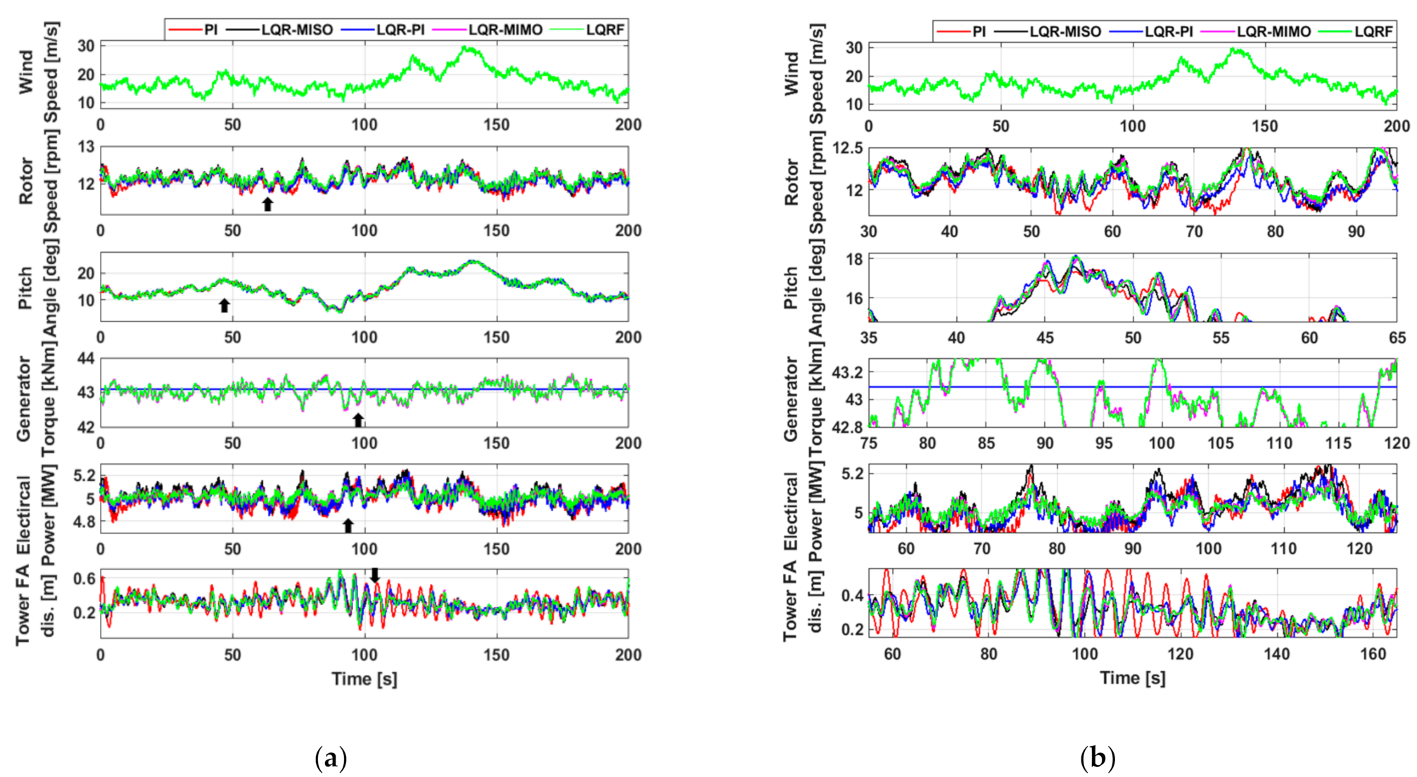
Dynamic simulations have been performed to compare performances of the proposed LQRF controller with those of the conventional PI, LQR-MISO, LQR-PI, and LQR-MIMO controllers that can be seen in the literature. Simulations were conducted with the NREL 5MW wind turbine at two different mean wind speeds, 12 m/s and 18 m/s, with a turbulence intensity of 20%. The results are shown in
Figure 12 and
Figure 13, respectively. Simulation results of the optimal control techniques can vary by the weights to the contribution from multiple wind turbine states that the designer determines. In these simulations, the weights were determined to reduce the rotor speed deviation while keeping the deviation of the tower top displacement small as shown in Equation (9).
Figure 12 shows the simulation results with the wind speed of 12 m/s.
Figure 12a, b are the zoomed-out and zoomed-in views of the same results, respectively. As can be seen in the figures, the results with the five different controllers mostly look similar. However, there exist differences in the deviation. In
Figure 12a, sudden drops are shown in the generator torque and the power when the conventional PI control was used. However, for other controllers the drops are reduced by different magnitudes. This kind of sudden drops in the generator torque and the power are often observed with the conventional PI controller due to the switching mechanism of the mode switch [
27] in turbulent winds. These sudden drops are shown more clearly in
Figure 12b. The conventional PI, LQR-MISO, LQR-PI controllers use similar torque and pitch control loops with a mode switch, and as the result, such sudden drops in the generator torque and the power are shown in all cases. However, the drop gets reduced with the LQR-MISO, and reduced further with the LQR-PI control. This kind of sudden drops are not shown in the LQR-MIMO, and the LQRF control because no mode switch is used in those controllers. In the rotor speed, the conventional PI and the LQR-MISO yielded the highest deviation. The rotor speed deviation was reduced for the LQR-PI, LQR-MIMO, and the LQRF control.
The simulation results are shown quantitatively in
Table 7. The mean values are not much different for simulations with five different controllers. However, there exist somewhat larger differences in the standard deviations. Based on the table, the LQR-PI, LQR-MIMO and the LQRF show better performances than the conventional PI and the LQR-MISO. Additionally, although the differences are not significant but the LQR-PI and the LQR-MIMO have similar performances but the LQRF shows the best performance. This means that the LQR-PI is a good choice in the case when the minimum change is required from the conventional PI. However, the LQR-PI is not a MIMO controller, and therefore the improvement of the performance is limited. The LQRF controller seems to be a good choice in the case when the conventional PI controller can be completely replaced by a new controller. This is because it is a MIMO controller that doesn’t need the mode switch and also the generator torque commands and the blade pitch commands are adjusted simultaneously to achieve better performances compared to the LQR-PI. Additionally, it shows slightly better performance than the LQR-MIMO control because it can consider nonlinear effects using fuzzy logic.
Figure 13 shows the simulation results with the wind speed of 18 m/s.
Figure 13a, b are the zoomed-out and zoomed-in views of the results, respectively. As in
Figure 12, the performances of five different controllers are not much different as a whole but they show some differences in the magnitude of deviations. The sudden drops in the generator torque and the power shown in
Figure 12 are not shown in
Figure 13 because the wind speed remains well above the rated wind speed at all time.
In
Figure 13a, the PI, LQR-MISO, and LQR-PI controllers maintain the constant rated generator torque because they are based on the conventional PI control, and the constant rated torque was used as the torque command for the rated power region in the conventional PI of this study. However, the LQR-MIMO, LQRF controllers continuously adjust the generator torque commands so that the power output is not much fluctuated from the rated power. The differences in the deviations of simulation results can be seen more clearly in
Figure 13b. As well as the power deviation, the rotor speed and the tower vibration are found to be much reduced by the LQRF controller compared with those by the conventional PI controller.
The quantitative simulation results are shown in
Table 8. As can be seen from the table, the LQR-PI, LQR-MIMO and the LQRF control show significantly better performances (smaller deviation) compared with the conventional PI and the LQR-MISO control. Although the LQR-PI, LQR-MIMO, and the LQRF control showed similar good performances, the LQRF was found to have slightly better performances than the other controllers like in
Table 7.
7. Conclusions
In this study, an LQR controller based on fuzzy logic (LQRF) is proposed for large wind turbines was designed. The controller is a MIMO controller that replaces the conventional torque and pitch controllers with a mode switch. For simulations, the proposed controller was applied to both the NREL 5MW wind turbine and a wind turbine scaled model with functions similar to those of large wind turbines. It was found from simulations that the proposed controller reduced the standard deviations of the power, rotor speed, and the tower vibration of both wind turbines compared with the conventional torque and pitch control.
The improvements in the performance were also experimentally verified with the wind turbine scaled model through wind tunnel tests. With the proposed LQRF controller, the standard deviations of the rotor speed and the power were reduced by 36.39% and 38.94%, respectively, and the tower vibration was reduced by 12.41%.
The LQ problem in this study has been tried to further optimize the performance of the controller using fuzzy logic to consider nonlinearity, but the problem of tuning time of weights remains. These problems are expected to be improved by combining learning-capable neural network techniques or genetic and evolutionary algorithms with the fuzzy inference technique used in this study. This approach will make the design process of optimal control techniques more systematic and easier.


