Article

PLC Automation and Control Strategy in a Stirling Solar Power System

1
National R&D Institute for Cryogenic and Isotopic Technologies, 240050 Rm. Valcea, Romania
2
Department of Engineering Thermodynamics, University POLITEHNICA of Bucharest, 060042 Bucharest, Romania
3
Faculty of Electrical Engineering and Computer Science, University “Stefan cel Mare” of Suceava, 720229 Suceava, Romania
4
Faculty of Building Services, Technical University of Cluj-Napoca, 400114 Cluj-Napoca, Romania
5
Energetics Faculty, University POLITEHNICA of Bucharest, 060042 Bucharest, Romania
*
Authors to whom correspondence should be addressed.
Energies 2020, 13(8), 1917; https://doi.org/10.3390/en13081917
Submission received: 23 March 2020 / Revised: 8 April 2020 / Accepted: 12 April 2020 / Published: 14 April 2020
(This article belongs to the Special Issue Fuel Cell Renewable Hybrid Power Systems)

Abstract

:
The Stirling engine together with a solar concentrator represents a solution for increasing energy efficiency. Thus, within the National Research and Development Institute for Cryogenic and Isotopic Technologies, an automation system was designed and implemented in order to control the processes inside the solar conversion unit using a programmable logic controller from Schneider Electric. The acquired parameters from the installed sensors were monitored using Unity Pro L software. The main objective of this paper is to solve the starting, operating, and shut-down sequences in safe conditions, as well as monitor the working parameters.

1. Introduction

The impact of integrating renewable energy sources from the environment solves one of the major problems regarding global warming and CO2 emissions. Fossil fuel resources, hydrocarbons, coal, and natural gas are all limited, cause pollution, and have a strong influence on carbon emissions, affecting the environment irreversibly [1].
Green, renewable energy sources, as an alternative to fossil fuels, are used by hybrid energy systems [2] based on high-efficiency technologies. For example, the solar concentrator that provides the energy needed to drive a Stirling engine [3], with a working cycle having the same name, created by the Scotsman Robert Stirling and patented in 1816 [4]. Thus, the Stirling engine appears as a promising option in the supply of energy compared to other traditional solutions based on renewable energy sources, with a reduced polluting effect similar to that of geothermal, solar, or biomass energy [5,6].
In the specialist literature, Zabalaga et al. presented in [7] an analysis in terms of energy efficiency and economic profitability of a hybrid energy system consisting of photovoltaic panels, a Stirling engine, and a battery system [8]. The dimensioning, using Homer software and, later, the simulation [9,10,11] of the starting and cooling sequences in MATLAB/Simulink T.M. 8.9 demonstrated a 69% reduction in greenhouse gas emissions, an 11% improvement in annual costs, and a 5% increase of energy efficiency compared to conventional diesel engine systems [12,13,14].
In [15], Islas et al. conducted a research study on the influence of several design variables and operating parameters over the performance of a 2 kW alpha-type Stirling engine, as well as methods for optimizing the major factors affecting engine efficiency. An important aspect is temperature and pressure control in the primary and secondary circuits of the Stirling engine.
Malali et al. discuss in [16] the effects of circumsolar radiation on the thermal efficiency of a Stirling engine–solar concentrator system, the mathematical model being realized in MATLAB. In the optimal case, the parameters thus obtained are used in the design of the hybrid system.
In [17], Zare and Saleh used the mathematical model of the Stirling engine and the Lyapunov method to predict the optimal operating conditions of a Stirling engine [18,19]. The starting sequences and the oscillations that may occur during operation were especially studied.
Buscemi et al. presented in [20] a hybrid energy system consisting of a solar concentrator and a 32 kW Stirling engine installed in Southern Italy. Their model is capable of predicting annual energy production, especially taking into account the level of dirt on the solar concentrator mirrors [21,22].
In [23], Arora et al. developed a genetic evolutionary algorithm in MATLAB for choosing the optimum values of the decision variables in order to obtain maximum power in terms of energy and heat, as well as an increased economic efficiency [24,25].
Based on the scientific literature, the novelty of this paper consists of the design and implementation of an automation and control system for the operation of a Stirling engine—this system being used so far only in other types of industrial installations.
Even though the use of programmable logic controllers (PLCs) and industrial automations is widely presented in literature, there are few to no cases where these are used in Stirling engine systems for the generation of both electrical and thermal energy, which increased the research team’s interest in approaching this topic.
One particular element of this automation, in comparison to others from the industrial sector, is related to the specificity of the Stirling engine system, namely the adaptation to operating requirements, starting sequences, normal operation, control and valve actuation for loading and unloading the working fluid, operation of the fan and cooling pump, controlled shut-down, overload protection, actuation of the safety curtain of the primary exchanger, monitoring of working parameters, temperature, and speed.
Another aspect was to ensure the recording of the parameters, the global automation transmission through bidirectional ethernet connection, including the positioning of the solar concentrator on the maximum flux of solar thermal irradiation, according to the data collected by the Solys2 weather station, which determines the solar coordinates of the Stirling engine solar concentrator location.
In this context, the installation developed in the National Research and Development Institute for Cryogenic and Isotopic Technologies in Romania has integrated a Stirling engine working together with a solar concentrator with the purpose of cogeneration of electricity (10 kW electric) and thermal energy (25 kW thermal) at a low cost [26].
In this paper, we have designed, tested, and optimized the starting, operating, and stopping sequences of a Tedom-modified Stirling alpha V191 engine, representing the conversion unit of the Sunflower 35 solar concentrator [27], through an automation system. In the laboratory, we designed the electrical installation and the automation system, we implemented practically the automation system [28,29], and we programmed the PLCs in order to realize the starting sequences and the opening of the valves for both the cooling system of the compressor and the charging system with helium. The automation also provides the protection and alarm system, control of the protection curtain, and command and control of the electric generator, the heat exchanger, and fan control for the Stirling engine.
Programmable logic controllers (PLCs) emulate the electrical scheme and the computer equipment built around a processor and are capable of controlling, through digital and analog input/output modules, one or more pieces of industrial equipment based on dedicated software [30].
The specific objectives of the present study, based on the automation design, are the following:
-
real-time monitoring of the parameters given by temperature, pressure, and rotation sensors;
-
recording of the operation results—electrical and thermal energy produced by the Stirling engine with solar concentrator, operating times, and various reports;
-
automation of start and stop sequences of the Stirling engine with an integrated protection system;
-
optimization of energy production according to the solar irradiation;
-
alarm management and security procedures (depending on various weather factors, on a working gas pressure drop, or on a rise in temperature outside the working domain);
-
remote transmission of the generated and acquired signals;
-
integration of the installation in complex cogeneration systems, as well as in energy optimization systems.
The main objective and focus of this paper is to solve the starting, operating, and shut-down sequences in safe conditions, as well as monitor the working parameters. The performance indicators are given by the stabilization of the temperature of the heat exchanger towards the working temperature, of the engine speed, and of the working pressure according to the values given by the producer [27].
The main findings are as follows:
  • implementation of the start and stop sequences of the test stand in safe conditions;
  • development of a human–machine interface (HMI) and an application for monitoring and data acquisition for the purpose of reporting safe operation;
  • automatization of the maximum solar radiation tracking system.
The solar concentrator using a Stirling engine offers a promising solution compared to other thermal installations that use solar energy, which is an unlimited renewable energy. The most-developed solar solutions currently used are the following:
photovoltaic panels;
tower solar concentrators;
thermal power stations, having solar collectors with parabolic trough or Fresnel systems (parabolic trough collectors (PTC) or linear Fresnel reflectors (LFR));
solar concentrators with a Stirling engine.
Even though photovoltaic panels are a great development, the solar concentrators using a Stirling engine accomplish a higher conversion efficiency of solar energy into electricity—29.4% [31]. By comparison, solar collectors that have a parabolic trough or Fresnel-type system can achieve a solar-to-electricity conversion efficiency of only 18–22% [32]. We observe a significant advantage for the Stirling solar concentrators. The tower solar concentrators achieve a solar-to-electricity conversion efficiency of about 20–27% [32], closer to that of the Stirling solar concentrator, but with considerably higher execution costs.
Another revealing analysis is related to the cost of obtaining a kWh, as presented by Zayeda [33]. The Stirling solar concentrator has a promising cost of USD 0.2565/kWh, compared to USD 0.4/kWh for the solar tower concentrators, and USD 0.14–0.16/kWh for solar collectors with a parabolic trough or Fresnel system. The best cost is for the photovoltaic panels, at USD 0.06/kWh.
Awana has shown in [34] the advantages of solar concentrators over photovoltaic systems. That is, a 35.7% higher electricity production, but also a better capacity-use factor and a better solar-to-electric conversion efficiency.
It was also shown that Stirling solar concentrators have led to a significant reduction in the cost of electricity production and, in addition, that the use of Stirling solar concentrator systems working on cogeneration of electric and thermal energy achieved an efficiency of over 60%.
The article was structured as follows: in the first part, in the introduction, the main objectives of the work were stated, up -to-date information was presented relating to PLC automation and control strategies used in Stirling solar power systems and a comparative study was conducted regarding the conversion efficiency and the cost of the proposed system with respect to other solar solutions. The second chapter, “Structure of the Automation and Control system”, presented two automation systems and identified the most suitable one, according to the equipment to be monitored/controlled. The third chapter, “Operating Principle”, presented the electrical schemes of the main and secondary circuits of the Stirling engine, as well as the automation schemes of the proposed system. In chapter four, “Case Study”, the experimental test stand was presented together with the data acquisition, control, and monitoring of the process parameters in tandem with the HMI interface. The results and discussions were presented in the fifth chapter and, finally, in the sixth chapter, the work was summarized and future perspectives were presented.

2. Structure of the Automation and Control System

2.1. Proposed Automation Systems: National Instruments and Schneider Electric

In order to realize the proposed installation, two solutions have been taken into account for the automation of the system, highlighting the advantages and disadvantages of each solution.
The first solution considered is to use the LabVIEW 19.0 HMI (human–machine interface) graphics interface provided by National Instruments, which offers various hardware platforms on which LabVIEW program developers implement operator interfaces, using programmable controllers that allow reconfigurable inputs/outputs (RIO), combining an improved, robust architecture with small industrial input/output modules, and time-sensitive networking (TSN). For monitoring the processes, either a PC (Personal Computer) can be connected remotely through a data transmission interface or a touchscreen can be used to enter the sequences directly. Figure 1 shows the hardware and software platform offered by National Instruments.
The second solution proposed is to use a system which has a Schneider Electric programmable automaton (Figure 2), a PLC control application made in Unity Pro L software (Figure 3), and the SCADA (HMI) graphical control and monitoring interface. In order to program these PLCs, the ladder diagram (LD) and function block diagram (FBD) programming languages are used, according to IEC (International Electrotechnical Commission) standard 61131-3.
Following a multicriterial analysis, taking into account the availability, the quality-price ratio, the software interface, and the applicability for the developed installation, the second option (Schneider Electric) was chosen.

2.2. Equipment Monitored/Controlled by the Automation System

The signals entering the automation system are given by temperature, pressure, and frequency sensors and the controlled equipment is represented by solenoid valves, fan, pump motors, electromagnets, an actuator motor, and a start motor impulse. Hardware components include connectors, input/output modules, PLCs with a processing unit, a multi-rack motherboard, and analog processing modules. Table 1 presents the main equipment to be monitored/controlled:

3. Operating Principle

In order to achieve and optimize the proposed installation, the Stirling solar conversion unit was studied and two main circuits were identified, depending on the working fluid, functionality, and destination:
-
main circuit of the Stirling engine (working fluid—Helium);
-
secondary circuit of the Stirling engine—cooling circuit (working fluid—water).
Figure 4 shows the main components of the Sunflower 35 solar concentrator, Figure 5 presents the Stirling solar conversion unit, and Figure 6 describes the test stand.
The test stand presented in Figure 6 contains the following components:
burner Gulliver BS2D, made by Riello, Italy, having the following characteristics: thermal power, 35/40 ÷ 91 kW; propane tank, 1.3/1.6 ÷ 3.5 Nm3/h; volume 26 L; burner control MG569; electrical power: 0.180 kW;
fan CA/line—10, made by SODECA, Spain, having the following characteristics: power 0.095 kW; speed 2460 ÷ 2720 s−1;
thermocouple type K, made by CAOM, Pascani, Romania;
mixing tube, Ø300 mm, length 800 mm, material 304 L;
gas exhaust pipe.
The use of the stand was justified by the numerous interactions, adjustments, modifications, and tests that would have been much more difficult and would not have allowed a fast reaction if the solar concentrator had been used as the heat source.

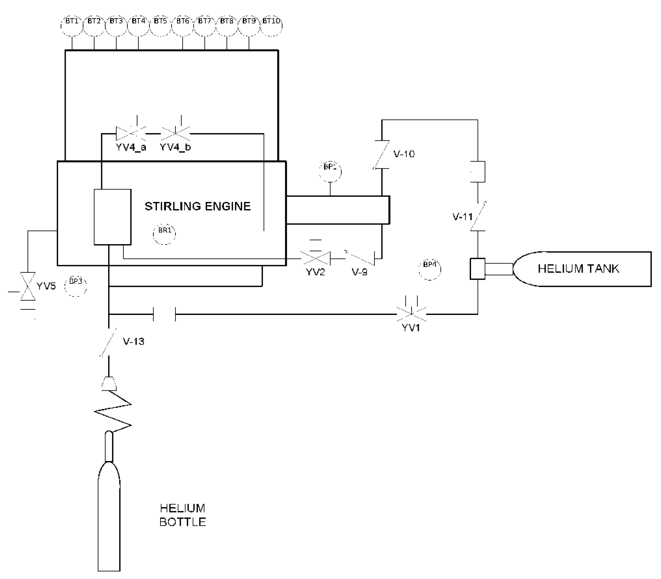
3.1. Main Circuit of the Stirling Engine (Working Fluid—Helium)

The main circuit of the Stirling engine is the most complex, having the following main blocks of equipment:
  • temperature sensors positioned on the main exchanger (hot bulb). Physically, there are 20 sensors, of which only 10, BT1–BT10, are used for temperature monitoring on the main exchanger and are placed in the connector in the local connection box, from where they are interconnected in the input/output connectors from the automation cabinet. The other 10 sensors are kept as back-up in case the used ones fail;
  • two pressure switches, one on the oil circuit, BP1, and the other on the water circuit, BP2;
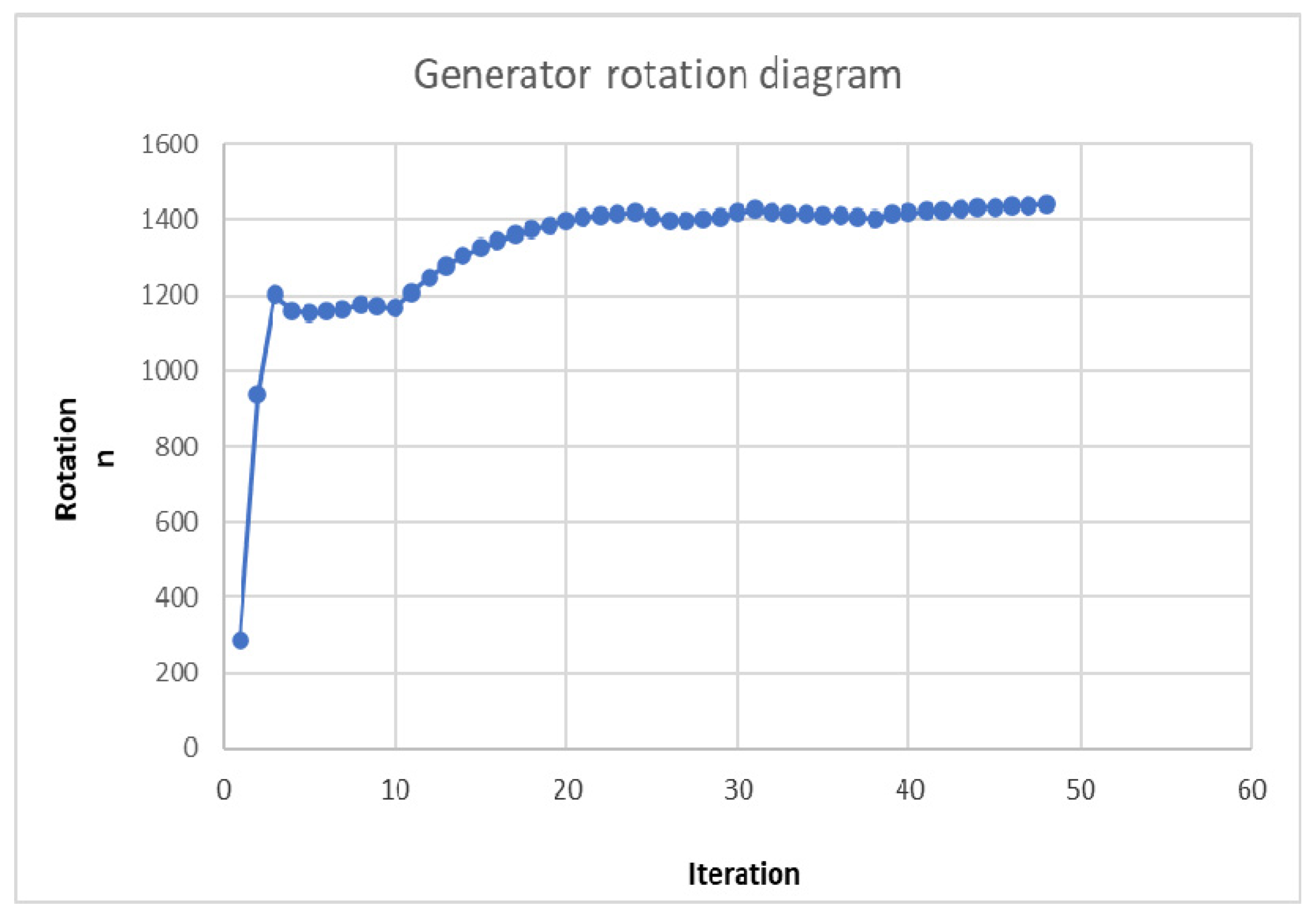
  • generator speed sensor BR1;
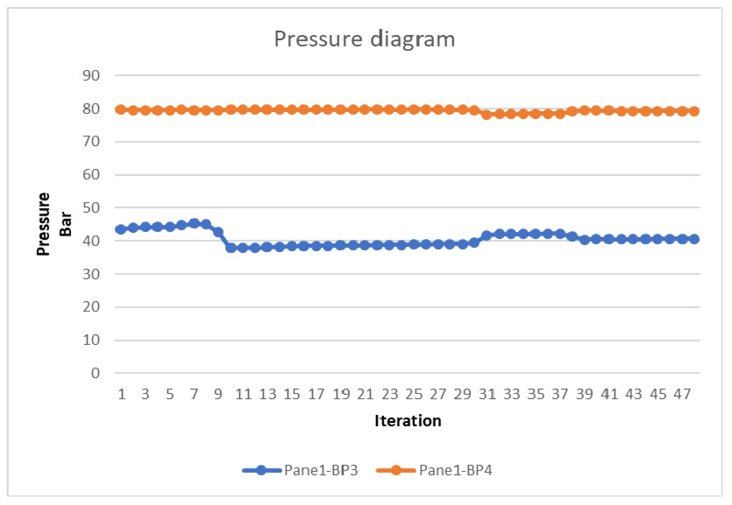
  • two pressure transmitters, one on the water heat-exchanger and the other on the oil circuit BP3, BP4;
  • the rotation sensor, BR1, which reads the rotations on the Stirling engine flywheel;
  • solenoid actuators, motors, etc.
Figure 7 shows the main circuit of the Stirling engine (working fluid—Helium)

3.2. Secondary Circuit of the Stirling Engine: Cooling Circuit (Working Fluid—Water)

The secondary circuit of the Stirling engine not only performs the cooling of the Stirling engine, but also supplies the thermal agent, being able to generate a power of up to 25 kW, identifying the following main blocks of equipment:
-
temperature sensors mounted on the cooling water circuit, BT11 and BT12;
-
pressure switch BP2 on the water circuit;
-
actuators, valves, motors, pulse compensator, etc.
Figure 8 presents the block diagram of the secondary circuit of the Stirling engine: cooling circuit (working fluid—water):

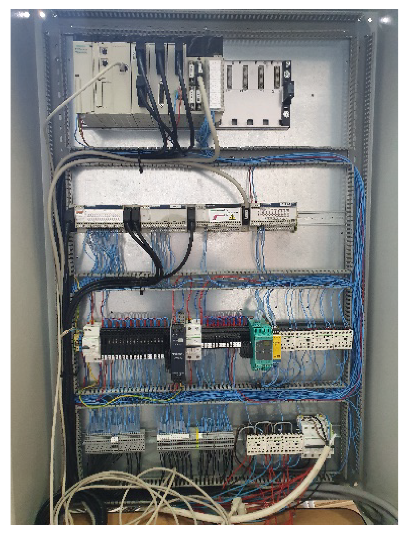
3.3. Electrical Automation Schemes

Starting from the two circuits, in which the components to be controlled by the Stirling engine automation were presented, the following schemes were developed:
  • connection diagrams of the temperature sensors from the primary exchanger BT1–BT10, from the cooling circuit BT12, rotation sensors BR1, pressure sensors BP3 and BP4, and the temperature sensor BT11, made in the rack modules two and three;
  • connection diagram of the actuation of the motors M1 – M4, realized in rack modules 4, 5, and 6;
  • power supply diagram for 24 VDC and 230 VAC;
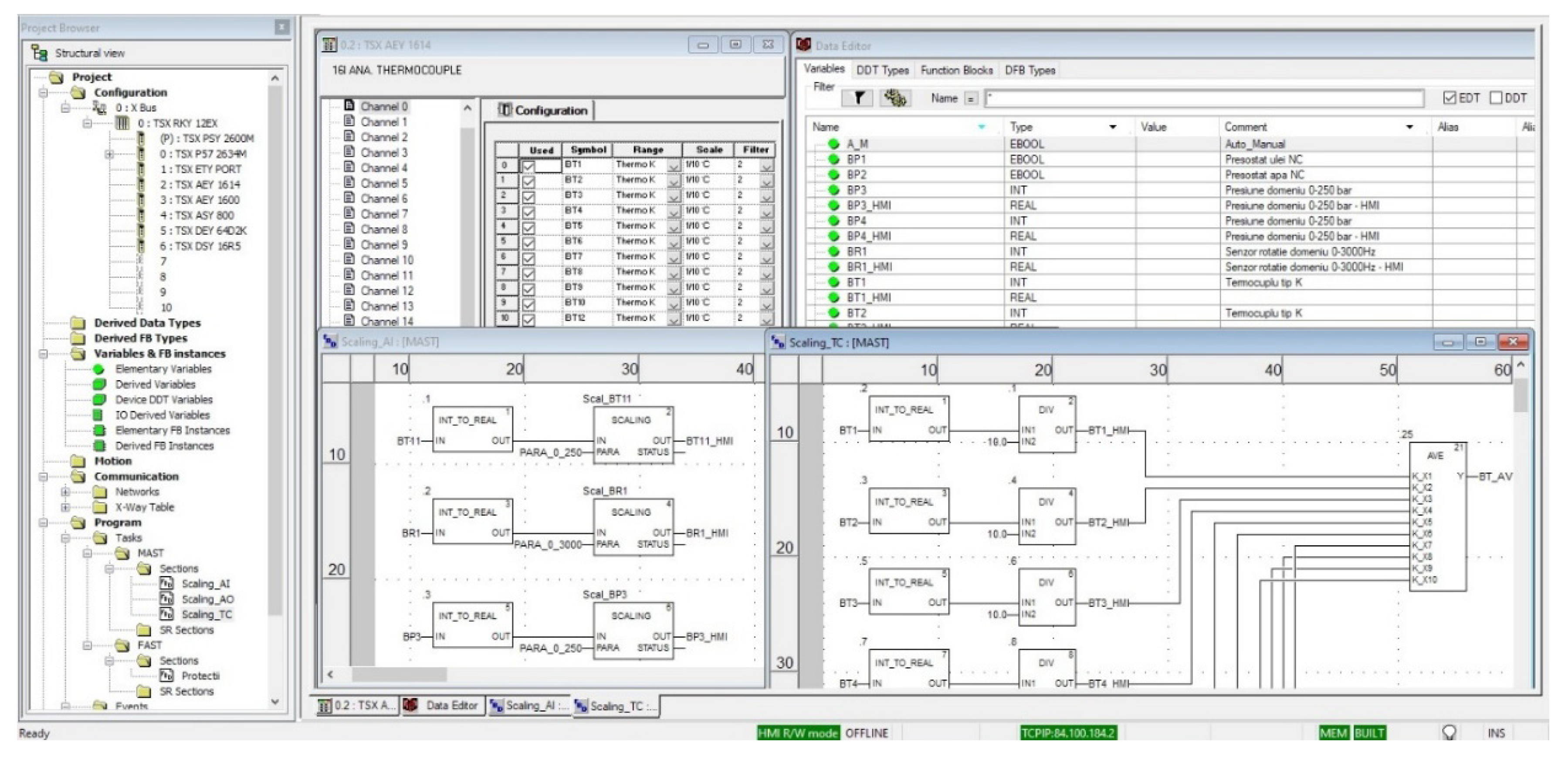
  • automation loops of temperature sensors BT1–BT10, and BT12, rack module two (Figure 9);
  • automation loops of the pressure sensors BP3, BP4, the rotation sensor BR1, and the temperature sensor on the housing of the motor crankcase BT11, rack module three (Figure 10);
  • automation loops of pressure sensors BP1, BP2, and actuator M2, rack modules four and five;
  • automation loops for actuating the solenoid valves YV1, YV2, YV4_a, YV4_b, YV5, and YV6, rack module six;
  • automation loops for actuating the motors M1, M2, M3, and M4, rack module six.

4. Case Study

The monitored parameters of the experimental set-up which are presented in Table 2 are the following: temperature, pressure, and rotation.
The experimental stand is composed of: the CPU (Central Processing Unit) with automation panel assembly (Figure 11), the local CPU connections box (Figure 12), and the automation panel box (Figure 13). Figure 14 shows the positioning of the temperature sensors on the primary exchanger.
The main objective of this study was to ensure the operation and functioning of the Stirling engine in safe conditions with the achievement of the designed performances.
The sensors mounted on the engine generate the following types of signal:
  • for continuous measurements—analogic signal 4–20 mA;
  • for discrete signals—zero potential contact.
The control signals generated from the control interface are of the following type:
  • for continuous signal—analogic signal 0–10 V;
  • for discrete signal—digital signal 24 VDC.
The signals from the motor are acquired in the connection box mounted on the Stirling engine and are transmitted to the control panel via multilayer cables. The control of the installation is implemented on a programable automaton—Modicon premium type.
The Stirling engine instrumentation system provides the following functions:
  • temperature measurement.
Twelve temperatures are measured through 11 thermocouple type-K sensors and one PT100-type sensor [37,38,39]. Minimum- or maximum-type alarms are generated in the PLC in order to keep the process within normal limits.
  • Pressure measurement.
Two relative pressures are measured in the mixing tank and the compression chamber through pressure transducers with an output signal of 4–20 mA; minimum- or maximum-type alarms are generated in the PLC in order to keep the process within normal limits.
  • Engine rotation measurement.
Engine rotation is measured by a frequency sensor connected to a signal interface that generates an output signal of 4–20 mA corresponding to the engine rotation.
  • Pump/fan control.
The control of the pump and of the fan is done as needed, either manually or automatically. Thus, in the distributed control system (DCS), command keys are virtually implemented for choosing manual or automatic man/auto mode, as well as for the manual on/off control. In manual mode, the pump and the fan are switched on/off directly by the operator by choosing the on or off position. In automatic mode, the pump and the fan start and stop according to the logic implemented in the DCS.
  • Control of automatic valves.
Valve control is done as needed, either manually or automatically. Thus, in the DCS, command keys are implemented virtually for choosing the manual/automatic (man/auto) mode, as well as for the manual control open/close. In manual mode, the valves are opened/closed directly by the operator by choosing the open or close position. In automatic mode, the valves open and close according to the logic implemented in the DCS.

4.1. Acquisition, Control, and Monitoring of the Process Parameters

The control system is a distributed type and consists of a Schneider Electric (PLC) programable automaton and a PLC control application done in Unity Pro software using the SCADA (HMI) human–machine control and monitoring interface.
The signals from the transducers and from the system equipment are taken over by the PLC where they are processed according to the program loaded in the internal memory of the programable automaton. The PLC transmits the data to the SCADA application through an OPC (Open Platform Communication) server (OLE (Object Linking and Embedding) for process control) via ethernet communication.
The architecture and structure of the program loaded in the PLC is realized in the programming language ladder diagram (LD) and function block diagram (FBD), according to the IEC standard 61131-3 (Figure 15) using the Unity Pro application.

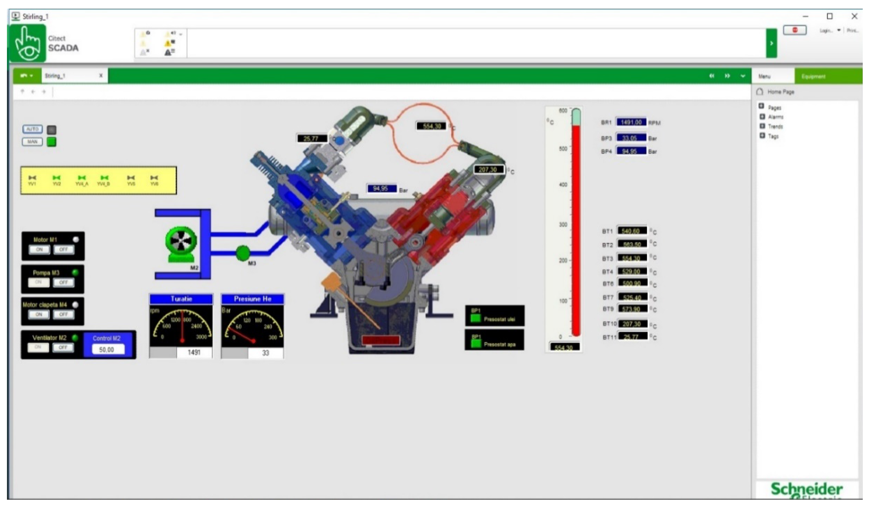
4.2. Human-Machine Interface HMI

The human-machine interface (HMI) for controlling and monitoring the parameters of the Stirling engine system is realized on the Citect Scada platform from Schneider Electric (Figure 16).
The HMI provides an interface between the system and its human user. This graphical interface converts the data received from the control system into human-intuitive representations of the process systems. The operator visualizes the scheme of the system, and can control the on/off of the dynamic equipment (cooling-water recirculation pump, fan, and solar radiation shutter motor), as well as adjusting the fan speed depending on the cooling-water temperature of the engine.
Two operating modes were realized: manual (MAN) and automatic (AUTO). In MAN mode, each equipment can be operated individually for single tests. When the AUTO mode is active (during normal engine operation), the protection program starts (protection related to minimum and maximum pressures, minimum and maximum temperatures, cooling pump on, cooling fan on, and state of pressure switches for cooling water pressure and helium pressure). The AUTO mode is made in Unity Pro and loaded into the PLC memory, each process parameter being automatically controlled by the PLC.
The graphic symbols for the equipment are created so that the condition of the equipment is indicated at any time by colors representing normal operation, start/stop, as well as the discrepancy between the command and the state of the equipment.
The collected data are saved in Excel files using the trend and process analyst functions in the Citect Scada application.
The significance of the colors on the graphical interface is presented in Table 3.

5. Results and Discussions

The testing procedure is the following:
powering the automation installation;
operation of the YV1 valve for charging the He circuit of the Stirling engine at 80 bar;
starting the supply of thermal energy with a propane thermal burner, with the following steps:
setting the temperature to 450–500 °C;
positioning of the type-K thermocouple for the primary exchanger of the Stirling engine;
propane supply by opening the 26 L cylinder tap;
ignition of the burner;
adjustment of air flow through the mixing chamber;
reading of the temperature transmitted by the type-K thermocouple.
When the minimum operating temperature exceeds 450 °C, start the Stirling engine using the Siemens electric generator connected to the engine, in order to start the rotation.
At this moment, the Stirling engine quickly enters the operating mode. The data monitored by the automation which are presented in this section confirm the stability of its operation. The small variations are due to the variation of the heat source over time—repeated tests were performed, the values collected were maintained in the same ranges.
For the shut-down sequence, the Riello burner heat source is reduced and, when the temperature drops to 350 °C, the engine diminishes its speed and stops.
Following the functioning tests, the automation and control installation has achieved stable operation under secure conditions.
The experimental data derived from the acquired and monitored parameters are further presented in the form of graphs using the trend and process analyst functions of the Citect Scada application.
In the graph presenting the variation of temperatures monitored by the automation (Figure 17), it can be clearly observed that the temperatures collected by the sensors located on the primary exchanger of the Stirling engine have a fast stabilization towards the working temperature, according to thermal power provided by the heat source. Each iteration is done at 330 ms.
Similarly, in the engine rotations/minute graph (Figure 18), the speed of the engine quickly reaches the synchronization speed of 1475 rot/min, keeping it constant.
These observations lead to the conclusion that the automation system performs the control of the operating processes of the Stirling engine.
The presentation of pressure monitoring on the Stirling BP3 engine and of the Helium cylinder pressure BP4 is shown in Figure 19.
By realizing the automation of the power generation unit using a Stirling engine, we performed the first stage for starting up the main module.
Another main stage is the implementation of the automation and control of the solar concentrator positioning. The supply of the sun position was made by a Solys2 installation (Figure 20) manufactured by Kipp & Zonen in order to determine the sun’s position. It uses two pyranometers, one for global radiation measurement and the other for diffused radiation, as well as a pyrheliometer with temperature sensor for direct solar radiation measurement.
The acquisition system transmits data to the control unit of the solar concentrator director that will position the axis of the concentrator in the direction of the sun through the two motors that control the rotations for elevation (vertical plane) and azimuth (horizontal plane), in order to obtain the maximum radiation.
According to [40], a computational analysis was completed using Ansys Fluent software, creating a model on which some simulations were performed for the exposure to thermal radiation around 1000 W/m2, a model validated by the experimental results.
Regarding the use of the engine with the realized automation and other energy sources, the tests performed confirmed the operation in the following cases:
the previously presented test which used a thermal energy source represented by a Riello gas burner;
another test which used a battery of electrical resistors with a nominal power of 12 kW, which ensured the operation at a lower, but stable level.
The Stirling engine has worked with different heat sources, with stable and repeatable operation under safe conditions.

6. Conclusions

The purpose of this study was to realize the automation of the solar energy conversion unit with respect to the system having a Stirling engine, electric generator, and secondary heat exchanger, which provides the electrical and thermal energy produced by the Stirling engine solar concentrator.
This automation aims to solve the starting sequences, the functioning in safe conditions, monitoring of the parameters during operation, protecting it, and safely stopping it.
These objectives have been met, however, depending on the behavior of the installation over time, they will be improved and completed as a result of the process of optimizing the functioning of the automation. By using an auxiliary source that supplies 16 kW, the functioning of the engine was obtained and control and security was ensured throughout the operation of the Stirling engine.
Since the integration and promotion of renewable energy sources is in continual growth, this attracted our attention to the use of a solar concentrator with a Stirling engine.
The advantages of automating the Stirling solar concentrator consist of:
-
creation of start and stop sequences of the test stand in safe conditions;
-
improved security protocols;
-
development of a monitoring application and data acquisition for reporting purposes;
-
positioning of the solar concentrator in the direction of the sun in order to obtain the maximum radiation.
The next steps will be to improve the security protocols in operation, as well as their succession.

Author Contributions

Conceptualization, D.-A.M., V.B., and I.M.; methodology, D.-A.M., C.B., and I.Ș.; software, D.-A.M., C.B., and I.M.; validation, V.B., M.S.R., and E.C.; formal analysis, D.-A.M. and C.B.; investigation, D.-A.M. and V.B.; resources, D.-A.M., C.B., and I.Ș.; data curation, V.B. and I.M.; writing—original draft preparation, D.-A.M.; writing—review and editing, M.S.R. and I.M.; visualization, D.-A.M., C.B., and I.Ș.; supervision, V.B., M.S.R., E.C., and I.M.; project administration, V.B.; funding acquisition, D.-A.M. All authors have read and agreed to the published version of the manuscript.

Funding

This research received no external funding.

Acknowledgments

This work was supported by a grant from the Romanian Ministry of Research and Innovation, CCCDI-UEFISCDI, project numbers PN-III-P1-1.2-PCCDI-2017-0776/No. 36 and PCCDI/15.03.2018, within PNCDI III. This work was carried out through the Nucleus Program, financed by the Ministry of Education and Research, project number PN 19 11 02 02.

Conflicts of Interest

The authors declare no conflict of interest.

References

  1. Kuban, L.; Stempka, J.; Tyliszczak, A. A 3D-CFD study of a g-type Stirling engine. Energy 2019, 169, 142–159. [Google Scholar] [CrossRef]
  2. Burke, M.J.; Stephens, J.C. Political power and renewable energy futures: A critical review. Energy Res. Soc. Sci. 2018, 35, 78–93. [Google Scholar] [CrossRef]
  3. Mancini, T.; Heller, P.; Butler, B.; Osborn, B.; Schiel, W.; Goldberg, V.; Buck, R.; Diver, R.; Andraka, C.; Moreno, J. Dish-Stirling systems: An overview of development and status. J. Sol. Energy Eng. 2003, 125, 135–151. [Google Scholar] [CrossRef]
  4. Stirling engine. Available online: https://en.wikipedia.org/wiki/Stirling_engine (accessed on 17 January 2020).
  5. Kongtragool, B.; Wongwises, S. A review of solar-powered stirling engines and low temperature differential stirling engine. Renew. Sustain. Energy Rev. 2003, 7, 131–154. [Google Scholar] [CrossRef]
  6. CSP World Website. Available online: http://www.cspworld.org/cspworldmap (accessed on 17 January 2020).
  7. Zabalaga, P.J.; Cardozo, E.; Campero, L.C.; Ramos, J.A. Performance Analysis of a Stirling Engine Hybrid Power System. Energies 2020, 13, 980. [Google Scholar] [CrossRef] [Green Version]
  8. Toro, C.; Rocco, M.V.; Colombo, E. Exergy and Thermoeconomic Analyses of Central Receiver Concentrated Solar Plants Using Air as Heat Transfer Fluid. Energies 2016, 9, 885. [Google Scholar] [CrossRef] [Green Version]
  9. Badea, G.; Felseghi, R.-A.; Varlam, M.; Filote, C.; Culcer, M.; Iliescu, M.; Răboacă, M.S. Design and Simulation of Romanian Solar Energy Charging Station for Electric Vehicles. Energies 2019, 12, 74. [Google Scholar] [CrossRef] [Green Version]
  10. Raboaca, M.S. Sustaining the passive house with hybrid energy photovoltaic panels—Fuel cell. Prog. Cryog. Isot. Sep. 2015, 18, 65–72. [Google Scholar]
  11. Cannistraro, M.; Mainardi, E.; Bottarelli, M. Testing a Dual-Source Heat Pump. Math. Modeling Eng. Probl. 2018, 5, 205–221. [Google Scholar] [CrossRef] [Green Version]
  12. González-Roubaud, E.; Pérez-Osorio, D.; Prieto, C. Review of commercial thermal energy storage in concentrated solar power plants: Steam vs. molten salts. Renew. Sustain. Energy Rev. 2017, 80, 133–148. [Google Scholar] [CrossRef]
  13. Dowling, A.W.; Zheng, T.; Zavala, V.M. Economic assessment of concentrated solar power technologies: A review. Renew. Sustain. Energy Rev. 2017, 72, 1019–1032. [Google Scholar] [CrossRef]
  14. Felseghi, R.A.; Carcadea, E.; Raboaca, M.S.; Trufin, C.N.; Filote, C. Hydrogen Fuel Cell Technology for the Sustainable Future of Stationary Applications. Energies 2019, 12, 4593. [Google Scholar] [CrossRef] [Green Version]
  15. Islas, S.; Beltran-Chacon, R.; Velazquez, N.; Leal-Chavez, D.; Lopez-Zavala, R.; Aguilar-Jimenez, J.A. A numerical study of the influence of design variable interactions on the performance of a Stirling engine System. Appl. Therm. Eng. 2020, 170, 115039. [Google Scholar] [CrossRef]
  16. Malali, P.; Chaturvedi, S.; Agarwala, R. Effects of circumsolar radiation on the optimal performance of a Stirling heat engine coupled with a parabolic dish solar collector. Appl. Therm. Eng. 2019, 159, 113961. [Google Scholar] [CrossRef]
  17. Zare, S.; Tavakolpur-Saleh, A.R. Predicting onset conditions of a free piston Stirling engine. Appl. Energy 2020, 262, 114488. [Google Scholar] [CrossRef]
  18. Vieira de Souza, L.E.; Gilmanova Cavalcante, A.M. Concentrated Solar Power deployment in emerging economies: The cases of China and Brazil. Renew. Sustain. Energy Rev. 2017, 72, 1094–1103. [Google Scholar] [CrossRef]
  19. Mohammadnia, A.; Ziapour, B.; Sedaghati, F.; Rosendhal, L.; Rezania, A. Utilizing thermoelectric generator as cavity temperature controller for temperature management in dish-Stirling engine. Applied Thermal Engineering 2020, 165, 114568. [Google Scholar] [CrossRef]
  20. Buscemi, A.; Lo Brano, V.; Chiaruzzi, C.; Ciulla, G.; Kalogeri, C. A validated energy model of a solar dish-Stirling system considering the cleanliness of mirrors. Appl. Energy 2020, 260, 114378. [Google Scholar] [CrossRef] [Green Version]
  21. Pelay, U.; Luo, L.; Fan, Y.; Stitou, D.; Rood, M. Thermal energy storage systems for concentrated solar power plants. Renew. Sustain. Energy Rev. 2017, 79, 82–100. [Google Scholar] [CrossRef]
  22. Liu, M.; Tay, N.H.S.; Bell, S.; Belusko, M.; Jacob, R.; Will, G.; Saman, W.; Bruno, F. Review on concentrating solar power plants and new developments in high temperature thermal energy storage technologies. Renew. Sustain. Energy Rev. 2016, 53, 1411–1432. [Google Scholar] [CrossRef]
  23. Arora, R.; Kaushik, S.C.; Kumar, R.; Arora, R. Multi-objective thermo-economic optimization of solar parabolic dish Stirling heat engine with regenerative losses using NSGA-II and decision making. Electr. Power Energy Syst. 2016, 74, 25–35. [Google Scholar] [CrossRef]
  24. Kannan, N.; Vakeesan, D. Solar energy for future world: A review. Renew. Sustain. Energy Rev. 2016, 62, 1092–1105. [Google Scholar] [CrossRef]
  25. Lovegrove, K.; Wyder, J.; Agrawal, A.; Borhuah, D.; McDonald, J.; Urkalan, K. Concentrating Solar Power in India; Report Commissioned by the Australian Government and Prepared by ITP Power; ITP Power: Bangkok, Thailand, 2011; ISBN 978-1-921299-52-0. [Google Scholar]
  26. Răboacă, M.S.; Badea, G.; Enache, A.; Filote, C.; Răsoi, G.; Rata, M.; Lavric, A.; Felseghi, R.A. Concentrating Solar Power Technologies. Energies 2019, 12, 1048. [Google Scholar] [CrossRef] [Green Version]
  27. Manual Instruction—V1.0—Sunflower 35 CONCENTRATION SOLAR PLANT—STROJÍRNY BOHDALICE. Available online: http://www.concentrating.eu/index.php/power-conversion-unit (accessed on 30 November 2014).
  28. Raboaca, M.S.; Dumitrescu, C.; Manta, I. Aircraft Trajectory Tracking Using Radar Equipment with Fuzzy Logic Algorithm. Mathematics 2020, 8, 207. [Google Scholar] [CrossRef] [Green Version]
  29. Aschilean, I.; Rasoi, G.; Raboaca, M.S.; Filote, C.; Culcer, M. Design and Concept of an Energy System Based on Renewable Sources for Greenhouse Sustainable Agriculture. Energies 2018, 11, 1201. [Google Scholar] [CrossRef] [Green Version]
  30. Alphonsus, E.R.; Abdullah, M.O. Mohammad Omar Abdullah. A review on the applications of programmable logic controllers (PLCs). Renew. Sustain. Energy Rev. 2016, 60, 1185–1205. [Google Scholar] [CrossRef]
  31. Punnathanam, V.; Koetcha, P. Effective multi-objective optimization of Stirling engine systems. Appl. Therm. Eng. 2016, 108, 261–276. [Google Scholar] [CrossRef]
  32. Pitz-Paal, P. Parabolic Trough—Linear Fresnel—Power Tower: A Technology Comparison. Available online: http://www.iass-potsdam.de/sites/default/files/files/12.5-iass_pitz-paal.pdf (accessed on 6 April 2020).
  33. Zayeda, M.; Zhaoa, J.; Lia, W.; Elsheik, A.; Zhaoa, Z.; Lia, K. Performance prediction and techno-economic analysis of solar dish/stirling system for electricity generation. Appl. Therm. Eng. 2020, 164, 114427. [Google Scholar] [CrossRef]
  34. Awana, A.; Zubaira, M.; Praveena, R.P.; Bhattib, A. Design and comparative analysis of photovoltaic and parabolic trough based CSP plants. Sol. Energy 2019, 183, 551–565. [Google Scholar] [CrossRef]
  35. CompactRIO. Available online: http://www.ni.com/ro-ro/shop/compactrio.html (accessed on 17 January 2020).
  36. Where is an Example MODICON RTU Unity Pro Project using DNP3 Protocol. Available online: https://www.schneider-electric.com/en/faqs/FA339010/ (accessed on 17 January 2020).
  37. Kabir, E.; Kumar, P.; Kumar, S.; Adelodun, A.A.; Kim, K.H. Solar energy: Potential and future prospects. Renew. Sustain. Energy Rev. 2018, 82, 894–900. [Google Scholar] [CrossRef]
  38. Law, E.W.; Kay, M.; Taylor, R.A. Calculating the financial value of a concentrated solar thermal plant operated using direct normal irradiance forecasts. Sol. Energy 2016, 125, 267–281. [Google Scholar] [CrossRef] [Green Version]
  39. Ehtiwesh, I.A.S.; Coelho, M.C.; Sousa, A.C.M. Exergetic and environmental life cycle assessment analysis of concentrated solar power plants. Renew. Sustain. Energy Rev. 2016, 56, 145–155. [Google Scholar] [CrossRef]
  40. Mocanu, D.A.; Badescu, V.; Carcadea, E.; Armeanu, A. Computational analysis of the tubular heat exchanger of an integrated energy generation system using a solar Stirling engine. U.P.B. Sci. Bull. 2020, 82, 139–150. [Google Scholar]
Figure 1. National Instruments hardware and software platform [35].
Energies 13 01917 g001
Figure 2. Schneider Electric programmable automaton [36].
Energies 13 01917 g002
Figure 3. Unity Pro L working interface.
Energies 13 01917 g003
Figure 4. Sunflower 35 solar concentrator components [27].
Energies 13 01917 g004
Figure 5. Solar conversion unit.
Energies 13 01917 g005
Figure 6. Test Stand.
Energies 13 01917 g006
Figure 7. Main circuit of the Stirling engine. Working fluid—Helium. BT1–BT10: temperature sensors; BP1 and BP2: pressure switches; BR1: rotation sensor and generator speed sensor; BP3 and BP4: pressure transmitters.
Energies 13 01917 g007
Figure 8. Secondary circuit of the Stirling engine, water-cooling. BT11 and BT12: temperature sensors.
Energies 13 01917 g008
Figure 9. Automation loops of temperature sensors BT1 - BT8.
Energies 13 01917 g009
Figure 10. Automation loops of pressure sensors BP3 and BP4, rotation sensor BR1, and temperature sensor on the motor crankcase BT11.
Energies 13 01917 g010
Figure 11. CPU and automation panel.
Energies 13 01917 g011
Figure 12. Local CPU connections.
Energies 13 01917 g012
Figure 13. Automation panel.
Energies 13 01917 g013
Figure 14. Positioning of temperature sensors on the primary exchanger.
Energies 13 01917 g014
Figure 15. Unity PRO Software—Stirling engine.
Energies 13 01917 g015
Figure 16. HMI control and monitoring interface. Process control screen.
Energies 13 01917 g016
Figure 17. Heat exchanger temperature diagram.
Energies 13 01917 g017
Figure 18. Generator rotation diagram.
Energies 13 01917 g018
Figure 19. Helium Stirling engine and bottle pressure diagram.
Energies 13 01917 g019
Figure 20. Solys2 solar detection station.
Energies 13 01917 g020
Table 1. Monitored/controlled equipment.
EquipmentModel
Pressure sensorsDrucksensor BA 520, Huba Control AG
I = 4....20 mA; U1 ≤ 30 V; I1 ≤ 100 mA; P1 ≤ 750 mW T = −30 ÷ 120 °C
FanEbm-papst Mulfingen GmbH&Co, W3G630GQ;3721-BA-ENU
Single phase; 230V; Speed: 1000 rot/min; P = 720 W; 140 Pa; T = −250 ÷ 60 °C
Rotation sensorBESM08EH-PSC15B-S04G, BALLUF
Ue = 24 Vcc; Ie = 200 mA; H = 15%; Ir = 20 µA; f = 3000 Hz; IP68; T = −25 ÷ 70 °C
Frequency signal adapterZKFD2-UFC-11.D produced by PEPPER+FUCHS which converts the frequency into proportional current 4 ÷ 20 mA
24 V DC supply (Power Rail); 1 mHz … 10 kHz; Ie 0/4 mA … 20 mA
Slot extension rackModicon Premium TSXRKY12EX
Communication module processorTSXP573634M
Power supply moduleTSXPSY2600M
ETHERNETTSX ETY 110 module
One analog input moduleTSX AEY 1600—16 voltage/current inputs
One analog input moduleTSX AEY 1614–16 thermocouple inputs
One analog output moduleTSX ASY 800—8 voltage/current outputs
One discrete output moduleTSX DSY 16R5—16 discrete relay outputs
One discrete input moduleTSX DEY 64D2K—64 discrete inputs
Table 2. Parameters of the experimental set-up.
No.TAGTypeDomainMeasured Parameter
1BT1Type K temperature sensor0–1000 °CHelium
2BT2Type K temperature sensor0–1000 °CHelium
3BT3Type K temperature sensor0–1000 °CHelium
4BT4Type K temperature sensor0–1000 °CHelium
5BT5Type K temperature sensor0–1000 °CHelium
6BT6Type K temperature sensor0–1000 °CHelium
7BT7Type K temperature sensor0–1000 °CHelium
8BT8Type K temperature sensor0–1000 °CHelium
9BT9Type K temperature sensor0–1000 °CHelium
10BT10Type K temperature sensor0–1000 °CHelium
11BT11Type PT100 temperature sensor0–250 °CCooling water
12BT12Type K temperature sensor0–1000 °CHelium
13BP3Pressure transmitter0–250 bar (g)Helium
14BP4Pressure transmitter0–250 bar (g)Helium
15BR1Rotation sensor0–3000 HzRotation
Table 3. Graphic interface color-assignment interpretation.
ValvesDynamic Equipment (Pumps, Compressors)Electric Heaters
ColorStateColorStateColorState
GrayClosedGrayOnGrayUnpowered
GreenOpenGreenOffGreenPowered
RedDiscrepancy/missingRedNo voltage
OrangeIn motion/partially open

