1. Introduction
The dynamic technological development of electric vehicles (EV) and different support instruments introduced in various countries according to EU directives encourage individual customers to invest in EVs. The goal of the European Union is to reduce the greenhouse gas emissions into the atmosphere by 2050 by 60% compared to 1990. One of the assumptions to achieve the above objective is halving the number of vehicles with conventional drive in the urban transport by 2030 and total elimination of such vehicles from cities by 2050 [
1].
There are three main types of EVs available on the market: hybrid vehicles (HEV), hybrid vehicles with the possibility of charging a battery pack (PHEV) and fully electric vehicles (BEV) [
2,
3]. The BEV vehicles are the subject of this paper. Due to the high energy density, reasonable battery life and acceptable recharging speed the lithium-ion batteries are used to power this type of vehicle [
4].
The increasing number of EVs may bring a significant impact on the supply network. The most negative aspect for the network is an uncontrolled EV charging process, especially if it takes place during a time overlapping with high power demand. The increase of peak load due to mass charging may lead to branch congestion and large voltage drops. This problem is described in the literature. The assessment framework of a plug-in electric vehicles (PEV) impact on the supplying network is proposed in [
5] taking into account the great uncertainty in many crucial assumptions and parameters (e.g., EV battery charging power and time). In [
6,
7] the rating of electricity demand profile is assessed on the basis of information about EV user behaviors. Furthermore, in [
8] the diagrams of medium voltage (MV) network loading are presented for a scenario where 52% of all used cars are EVs. It is shown that dump charging can cause peak a power increase by about 100% and controllable charging is necessary to avoid network disruptions. Similarly, in [
9,
10] the impact of the increased number of EVs on the operation of low voltage (LV) power network by both controlled and uncontrolled EVs charging is analyzed. Different charging strategies are tested and compared in [
11,
12,
13]. The concept of using renewables, in particular the solar panels, in charging infrastructure is discussed in [
14].
The impact of EVs on the supply network significantly depends on EV user behaviors. If EV is used for commercial purposes or to travel for longer distances, it requires the infrastructure of fast and superfast chargers. In that case the location of charging points must be based on factors such as EV ranges, road infrastructure, investment costs, etc. In certain cases, there will be a need to reinforce a supply network and so the planning is crucial to minimize additional costs. The methodology for planning minimal fast charging infrastructure deployment is evaluated and depicted in [
15].
If the user exploits EV on relatively short distances, for example for commuting, the EV can be charged at home in the evening. At present this is the most typical scenario and it will be discussed further. While the EV is connected to the home electrical installation, the energy stored in EV battery can be used to support the installation operation and improve the reliability of supply. Such an EV service, called the vehicle-to-home (V2H), is especially useful in the case of supply network failure or when the EV user wants to reduce energy costs by using an EV battery to supply loads in the period of high energy prices.
Benefits from using EV for additional services have already been indicated in the literature [
16]. It is shown that through demand side management (DSM) the V2H may support the local loads during severe supply network loading or outages, hence alleviating energy demand on the network and its reliability requirements. In [
17] an active management model integrated with generation curtailment mechanism and the charging/discharging management of plug-in EVs was built for the local distribution system. In [
18,
19,
20] PEVs are used for the backup power during an outage and on the basis of residential energy usage data, the duration of backup power that could be achieved is identified. Similarly, in [
21,
22] EVs are used as energy storage for a local smart grid to reduce energy costs. In [
23] the exploitation of vehicle-to-grid (V2G) services for power quality improvement is discussed. The optimal charge/discharge schedule for an EV plugged into a smart building is presented in [
24,
25] taking into account time-varying electricity pricing schemes.
At present the V2H and V2G services require an off-board bi-directional inverter which generate high additional costs. In addition, the size of such an inverter is not without significance, especially in the context of limited space in garages or parking lots. In this paper, authors analyze the usage of an on-board motor inverter (instead of off-board) for V2H services. It means that the motor inverter is used for both: motor propulsion and ancillary (V2G/V2H) services. Different approaches to the adaptation of motor converters for the ancillary services are available in the literature. The review of the drivelines in all-electric vehicles is presented in [
26]. The topology of an on-board integrated battery charger using an asymmetrical nine-phase machine is described in [
27]. In [
28], a single-phase integrated charger, using the EV propulsion machine and its traction converter, is introduced.
The presented literature concentrates on indicating the possible benefits of the V2H services for EV users and the supplying network operators. However, to implement the additional functionalities of EV some technical issues should be examined including the control of EV motor inverter. In this paper the authors present an original simulation model, which can be a useful tool for both: the examination of EV motor inverter for V2H services and for the adaptation of home installation for such services.
The paper is arranged as follows. In
Section 2 the EV user behavior scenarios are identified to justify the possibilities and significance of EV additional functionalities. Then in
Section 3 we describe the simulation model. In the next Section, we present the simulation results for the chosen case study. The paper finishes with some conclusions.
2. EV User Behavior Scenario and V2H Charging Strategy
The availability of EV to be used for V2H services depends on EV user behaviors, which are unpredictable to a large extent. However, some typical user behaviors can be identified on the basis of factors describing the way of EV exploitation, i.e.,:
the distance, which a user drives during one day;
the place, where a user charges their electric car;
the time, when a user charges his electric car.
In this paper, the following scenario of EV exploitation is assumed. The EV is used in urban and non-urban areas for commuting. The vehicle is mainly charged on a private property. The most probable choice is charging in the user’s private garage in the evening, less probable is charging in the workplace during the day.
Currently the typical charging solutions may include: AC on-board charger (rectifier), or off-board DC charger, or on-board motor converter (also used for motor propulsion, braking energy regeneration and battery charging). In a further consideration, only the controlled AC charging, with the use of motor inverter, will be dealt with.
The control strategy applied defines charging and control parameters [
29] and requires infrastructure. A vehicle used for commuting is parked most of the day and can be connected to the electric installation. Hence, it is justified to extend the charging control strategy in order to use the EV battery as energy storage for the EV user needs.
The control of the charging process can be based on the tariff signal and the power limit value set by the distribution system operator (DSO). This strategy is beneficial for both the EV user and the network operator. The EV user reduces energy costs and the DSO receives network management opportunities (such as network load control).
The utilization of energy storage devices by end-users has been known for a long time and reported in the literature [
30,
31,
32,
33]. The typical application concerns a peak-shaving. When a distinction is made in tariffs between peak and off-peak hours, it is profitable for an end-users to reduce the peak demand. The EV battery is charged during off-peak hours, when energy is cheaper, and it is discharged during peak load periods. For EV users the reduction of peak power demand means decreasing demand charges. It should be noted that the peak demand occurs usually in the evening time period, so, according to the described scenario, while the EV is parked and its battery is available for ancillary service.
Another useful application of energy storage in LV installations is the supply of loads during dips and short interruptions. Its purpose is lowering the costs of losses incurred by end-users due to such disturbances in the network.
According to authors the infrastructure for the V2H services requires both the EV motor inverter and the building installation equipped with a home energy management system (HEMS) (
Figure 1). HEMS is responsible for the calculation of the starting and ending time of charging or discharging processes. It is based on the following parameters:
current energy cost;
battery state of charge (SOC);
current energy consumption at home;
EV user needs (time when EV user exploits their car).
The vehicle should be connected to the AC power network via dedicated EVSE (Electric Vehicle Suppling Equipment) i.e., socket outlet, connecting cable and wallbox. Communication between EV and EVSE must be bi-directional.
3. Description of EV Simulation Model
3.1. Asumptions
During driving, the EV motor inverter provides power to its motor or is used for regenerative braking. While an EV is parked, the motor inverter is connected to 3-phase LV home installation and is used to charge the batteries or for the V2H services such as energy storage operation or uninterruptable power supply (UPS). This functionality requires an appropriate control system and procedures to run depending on the function being performed: drive, energy storage or UPS (when the installation is disconnected from the network). The controller is located on-board the vehicle. Its operation modes and settings should include all limitations regarding all the cooperating devices: battery, vehicle engine, electric loads and the supplying feeder.
During driving the EV driver controls the power fed to the EV motor within the limits of its rated power (using accelerator and brake pedals).
While EV is parked and connected to the home installation, the battery can be charged or discharged according to the user’s decision or predefined profile. The amount of power drawn from or returned to the customer installation is limited by EV motor rated power, technical parameters of home installation and should be managed by the HEMS. Additionally, it should be noted that every EV is equipped with the on-board battery management systems (BMS). It is responsible for battery protection, monitoring and controlling its state. The HEMS cannot and should not have priority over BMS so it cannot jeopardize the battery safety. However, HEMS has access to the additional information (the energy tariffs, current energy consumption at home or other EV user preferences). That data can be used to effectively manage services like the peak shaving or planning the charging schedule.
The UPS option requires fully autonomous operation of the controller in order to balance an active and reactive power in the user’s home installation (islanded operation). The amount of power drawn from or returned to the customer installation is limited by EV motor rated power and technical parameters of the home installation.
The objective of the presented model is to create a simulation tool to examine and evaluate the EV capability for V2H services. In particular, the model can be used to:
evaluate the possibilities of EV inverter construction in terms of the ability to provide additional functionalities for achieving technical and economic benefits for EV users;
evaluate the home electric installation with regard to its abilities for the islanded operation with the use of an EV battery system;
verify the EV control algorithms and the selection of settings according to EV user’s requirements.
3.2. Model Structure
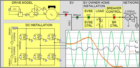
The presented EV simulation model, for which the general scheme is shown in
Figure 2, was built in the PSCAD program [
34]. The model encompasses the following modules: part of LV distribution network (NETWORK), EV user electric home installation supplied from the network (EV OWNER HOME INSTALLATION) and the on-board EV infrastructure (EV).
3.2.1. NETWORK Module
The network module consists of two blocks: SUPPLY and CONTROL of 3.ph, 2.ph, 1.ph SHORT CIRCUIT. The first block include ideal 3-phase voltage source of nominal voltage 15 kV and 15/0.4 kV distribution transformer supplying LV busbars (SUPPLY). The second allow the emulation of different, asymmetrical faults in the network and illustrate their effects at the point of coupling with end-user installation. The beginning and duration of each fault can be set using Time Fault Logic blocks.
3.2.2. EV OWNER INSTALLATION Module
User installation module is represented by R, L load block (LOAD), which through a BR switch is connected to the transformer LV busbars. The value of load impedance can be changed with constant tgφ. The EVSE terminal has electrical and control circuits. The CNT switch is controlled by the EVSE CTRL block.
The BR switch is controlled by the BRAKER CTRL block. In this block the supplying network voltage vector
vn is monitored and if the voltage exceeds permissible values, the switch is opened. The controller can close the breaker only when the voltage vectors
vn and
vh, on both sides of the switch, expressed by Equations (1) and (2), fulfil the synchronization requirements.
where:
vh, Vh, ωh, φh—instantaneous value, module, angular velocity and phase angle of voltage vector in end-user (home) installation in α, β coordinates.
vn, Vn, ωn, φn—instantaneous value, module, angular velocity and phase angle of supplying network voltage vector in α, β coordinates.
3.2.3. EV Module
The EV module consists of four parts: a drive module (DRIVE MODEL), a DC circuit (DC INSTALLATION), a harmonic filter (H.F. FILTER) and a central controller (EV CONTROLLER). They are described below.
DRIVE MODEL is based on the equation of rotary motion dynamics:
where:
J—moment of machine inertia brought to the machine shaft,
w—instantaneous value of the angular velocity of the machine rotor,
Te, Tm—electromagnetic torque and mechanical torque in the function of w.
The EV engine is represented by the module of a synchronous machine with permanent magnets. The integral part imitates the car inertia brought to the machine shaft. The input of this block is the sum of torques: electromagnetic driving Te depended on the current generated by the inverter and provided to the vehicle engine and mechanical Tm braking the car’s movement. The output is the value of the machine’s angular velocity w. It is assumed that the resistance to the movement and so the torque Tm are proportional to the angular velocity w of the car.
DC INSTALLATION represents EV battery and DC/AC motor inverter. The battery is represented by the DC source. The inverter is built as three-phase (6T) bridge of gate turn-off (GTO) thyristors. Firing pulses to thyristors are generated using pulse-width modulation (PWM) technique in the block of Inverter Current Controller. Hysteresis control is applied, in which the inverter AC current iinv reproduces the reference current vector iref determined in the block of EV CONTROLLER.
In the EV module passive filter (H.F.FILTER) and the remaining R, L, C elements visible in the simulator diagram are used to reduce current harmonics of high frequencies resulting from thyristor switches operation.
Two EV operation modes are modelled in the simulator: Driving and Parking. They can be selected by the position of MODE switch in EV CONTROL panel. For the first mode the switch should be set to the DRIVE position. It results in opening BRKpark switch and closing BRKev switch. With BRKev closed the EV inverter is connected to the stator of the synchronous machine and the EV is ready to drive. For the parking mode the position PARK at the control panel should be selected—it causes BRKpark switch to close. As a result, the connection between the EV inverter and EVSE (user installation) is established.
3.3. EV Control during Driving and Parking
The operation of EV devices is managed by an EV CONTROLLER block. For each operation mode it determines the value of reference current vector iref applied to the inverter. In the DRIVING mode the vector module is the function of control signal INV CTRL setting (representing accelerator and brake pedals). Its angular speed is equal to the synchronous machine angular velocity w.
In this case the vector of stator current is practically equal to iref vector, i.e., it rotates with the same angular velocity as the permanent magnet magnetic flux of the rotor. This results in the electromagnetic torque Te driving or braking the vehicle depending on sign of the INV CTRL signal.
In the PARKING mode, after closing the switch CNT, all control and power circuits of the car are connected to the EVSE (part of “EV USER INSTALLATION” module). The EV can perform a chosen function (charging or ancillary services). Two control options are possible depending on the state of the supply network:
In the first option the inverter transmits active power equal to the value set on the INV CTRL slider (in this case the INV CTRL setting can be determined by the Home Energy Management System). For positive signal value the current is in phase with the supplying voltage, which means that the EV batteries are charging. If the signal has a negative value, the current is in opposite phase to the voltage, which means energy is supplied to the consumer installation. EV CONTROLLER block determines reference current vector according to the formula:
where:
Equation (4) is based on the definition of instantaneous power in the machine stator. Its derivation is provided in
Appendix A.
The second option (UPS) is activated if there is a fault in the supply network. It results in the BR switch opening. In this case the EV function is to supply the consumer loads with voltage close to nominal. The reference current values are determined to ensure active and reactive power balance within the consumer installation. Simultaneously the voltage in the home installation is compared with the supplying network voltage in block BRAKE CTRL. If the network fault is eliminated the switch BR can be reclosed. Then, the EV CONTROLLER module comes back to performing the function it did before the disturbance.
4. Simulation
In order to demonstrate the performance of the developed model, the following scenarios were simulated in sequence, in single calculation cycle, i.e.,:
driving state, in which the EV is driving (accelerate and brake several times);
parking state, in which the vehicle is connected to the EVSE and operates as energy storage system;
parking state, in which the vehicle is connected to the EVSE, the battery energy storage operation is interrupted by faults in the supply network causing the EV operate as UPS system.
Time constant representing the inertia of the car was reduced in such a way that all states could be examined in one simulation and presented in one graph,
Figure 3. The states of all switches included in the simulator diagram and the waveforms of quantities enabling the evaluation of the modelled devices work in transient states were recorded. Individual operation states are presented in
Figure 4,
Figure 5,
Figure 6,
Figure 7 and
Figure 8, respectively.
In the first scenario (driving state) it was assumed that the vehicle accelerates and brakes to adapt its speed (
w) to the road traffic conditions, see
Figure 4. During the EV acceleration, electromagnetic torque (
Te) of the EV motor reaches its maximum value. When the road conditions prevent further acceleration (the driver releases the accelerator pedal), the electromagnetic torque reverses and the vehicle begins to decelerate. During the acceleration, when the invertor current (
iinv) and voltage (
vinv) are in opposite phases, the energy is transferred from batteries to the engine. Conversely, during regenerative braking, the engine operates as a generator, thus the inverter current and voltage are in phase, the energy is transferred from engine to the batteries.
During the next scenario the vehicle is parked and connected to the supply network, see
Figure 5. The bi-directional power flow is enabled, thus the execution of V2H services can be applied. This service can be controlled by the home energy management system on the basis of factors such as energy prices, user requirements, SOC of EV battery or home installation rated power. The voltages of the traction invertor (
vinv), the voltage in the home installation (
vh) and the voltage in the supply network (
vn) are equal. The inverter current (
iinv) changes (amplitude, phase) so the power can be transferred from or to the supply network. In
Figure 5 the phase of inverter current corresponds to the battery current (
IDC). When the on-board motor inverter operates as the battery charger (
IDC is positive) the voltage and invertor current are in phase. When energy is transferred to the customer installation (battery discharging,
IDC is negative) the phase between current and voltage is shifted by 180 degrees.
The next three drawings correspond to the third scenario, i.e.,: the 3-phase short circuit—
Figure 6, the 2-phase short circuit—
Figure 7 and the single-phase short circuit—
Figure 8. In all the figures, the order of events is the same. The simulation starts with the EV battery being charged. The voltages of the motor invertor, home installation and supplying network are the same. The motor invertor current and voltage are in phase. Then, the fault in the supply network occurs, which results in
vinv,
vn and
vh voltages decreasing, respective to the type of short circuit. In the response to the network fault, the protection controller trips the BR breaker. The vehicle inverter changes control strategy from battery charger to UPS and the home installation starts the islanded operation. One can notice that the home installation voltage reaches nominal value immediately. Moreover, the amplitude of invertor current changes respective to the customers loads. During island operation the EV inverter operates autonomously. When the fault in the supply network is removed, the synchronization process can be started. When the voltages in the home installation and in the supply network are in phase the BR breaker is reclosed and the EV inverter returns to the battery charging operation that can be controlled by the HEMS again.
5. Conclusions
The potential advantages of the V2H services using the off-board inverters are well described in the literature. The novelty of this paper is the reference to the applicable use of on-board 3-phase motor inverter and its control system for the both EV charging and ancillary services—V2H. Such an approach is beneficial since additional infrastructure costs are minimal.
In this paper authors concentrated on creating the accurate test-bed in the PSCAD environment that can be utilized to:
verify the EV capacity to provide V2H services;
assess the developed control system for EV on-board motor inverter;
evaluate the requirements that the home installation should meet to enable V2H services (including operation of protection devices and synchronization system);
evaluate the operation of the EV motor inverter and protection devices during faults in the supply network.
The conducted tests confirmed that the EV on-board single structure (consisting of motor inverter, its control system, switches/breakers) is sufficient to provide V2H services in the home installation equipped with:
Since there is no need for additional off-board inverter the cost of V2H services implementation can be minimized. In other words, the V2H services give the EV owner the opportunity to provide emergency power supply (with minimal additional infrastructure expenses) and potentially lower the costs of electrical energy (if a home energy management system is used).
It should be noted that the availability and effectiveness of V2H services (such as peak shaving or uninterruptable power supply) depend on energy stored in the EV batteries. Thus, it is strictly related to the vehicle usage profile (availability of EV battery).
As driving capabilities, the main functionality of EV, should not be limited by additional V2H services, the integration with the home energy management system seems to be advantageous. HEMS can determine the EV battery charging/discharging pattern including restrictions resulting from:
Although the presented simulation results confirm that the EV motor inverter technology is ready for the V2H services, the limited capacity of the EV battery and the impact of charging/discharging cycles might be an issue. On the other hand, intensive research is being carried out into the development of storage technologies, so this should not be a problem in the future.


