1. Introduction
Flapping wing micro air vehicles (FWMAVs) are biologically inspired vehicles that designers hope will mimic the maneuverability and dynamics observed in birds and insects. Energy is the key enabler of flight, both in terms of efficiency and density. FWMAVs have an additional problem because biomimetic implementations combines propulsion and control using linear actuators (muscles), creating an articulation challenge for the well understood rotating machinery.
There have been many examples over the years like the RoboBee by Harvard that was the first FWMAV to achieve liftoff and is now an untethered system [
1,
2]. RoboBee utilises piezoelectric actuators configured to undergo small bending amplitudes when energised. This bending motion is then amplified through a four-bar mechanism to achieve the desired flapping amplitude. These systems use an actuator with a high power density of 467 W/kg [
3]. This power density is high when compared to the flight muscles of a fruit fly, which has an estimated power density of 80 W/kg [
4]. However, a hindrance to the successful implementation of piezoelectric actuators is the requirement for light weight and efficient boost converters generating in the order of 200 V. This must be generated from a energy store such as such single cell batteries, super-capacitors or solar panels which are generally low voltage. This converter circuity as a result consumes a significant proportion of the mass budget of the aircraft. Alternatives to piezoelectric actuators have typically been various configurations of electromagnetic rotary motors. These include the use of wing coupled rotary motors in conjunction with large reduction gearboxes to achieve useful torques and velocities. This actuator type loses power in the gear train with reported efficiencies around 60% and electrical to aerodynamic power conversion of approximately 10% [
5]. Other examples capable of lift off have used crank and slider mechanisms that convert rotary motion from brushless motors into flapping motion [
6]. Beyond conventional rotary motors, there have been attempts to use unique motor topologies to achieve liftoff. Roll et al. used a high-frequency oscillating actuator with magnetic virtual-spring to provide a 4.0 g system with an estimated efficiency of 10% [
7] and the 80 mg craft by Zou et al. [
8] was the first to achieve liftoff with a linear electromagnetic actuator [
8]. The use of a linear electromagnetic actuator provides a compelling method of actuation as the linear motion it creates has similarities to muscles with the additional ability to apply forces in both directions. However, there has been little further research into the use of these actuators. This is a result of the poor efficiency that Zou et al. [
8] reported for these actuators. With 1.2 W of power being consumed by an 80 mg craft in flight, energy efficiency is expected to be very low.
This study will model the performance of the linear electromagnetic actuator and provide a holistic comparison of this topology compared to current generation piezoelectric actuators. Exploring how system design can affect the performance of the craft while considering the implications for power electronics.
2. Mechanics
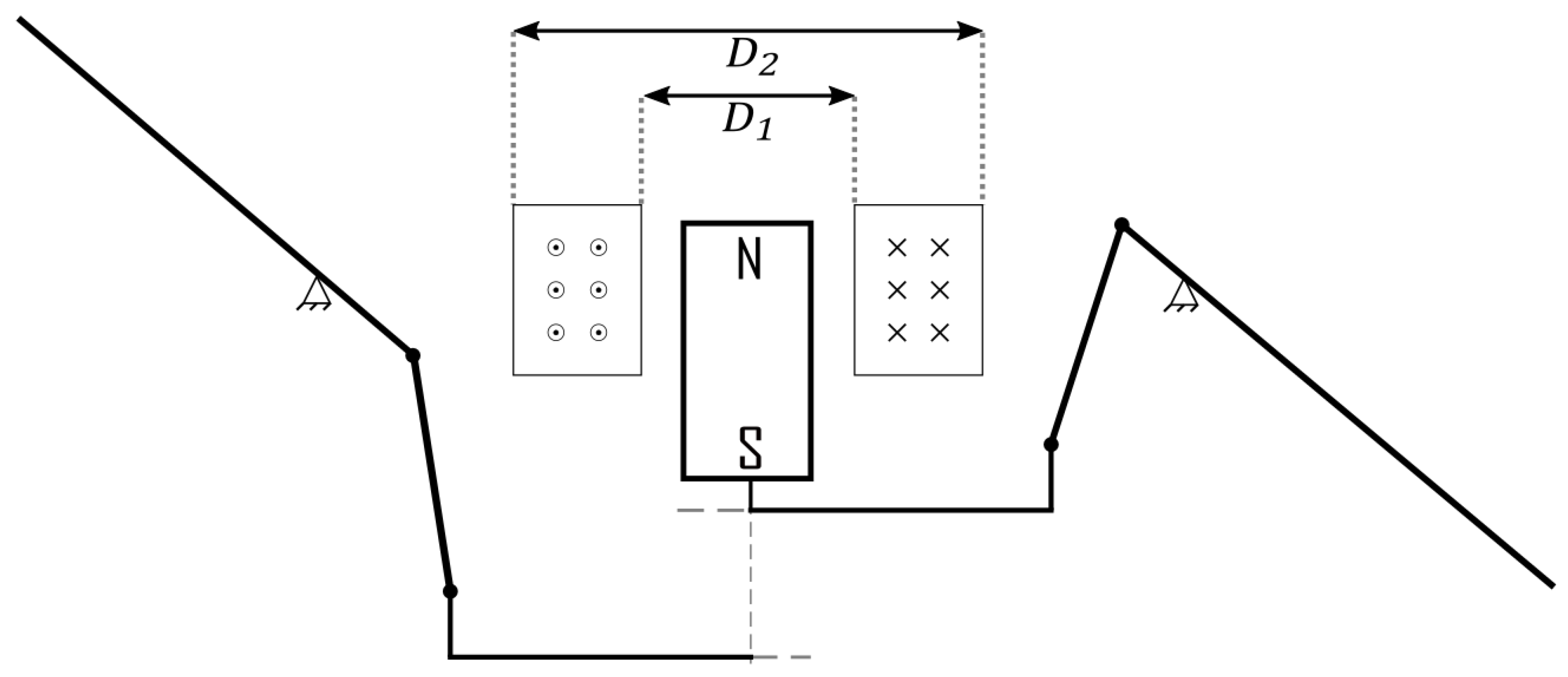
The major components of this system are the actuator, consisting of a single magnet and coil producing force, a mechanism shown in
Figure 1, to convert the linear motion into the desired wing rotation and the wings themselves that generate the lift force. The system that will be described in this analysis will be a single actuator 2 wing system of the same parameters published by Zou et al. [
8]. It is assumed that the actuator can directly control only the flapping angle and that the second degree of freedom which describes the rotation around the span axis, is controlled by the aerodynamic and inertial forces via a flexible hinge. This system will flap the wings with an amplitude of
and will assume a rotational profile of
.
2.1. Aerodynamic Forces
Rotation or flapping of a wing generates a normal force to the surface of the wing. This force can be separated into components of lift and drag which are commonly used to analyse flapping wing flight [
9]. Lift and drag can be written as
where
is the chordwise length and
and
are the coefficients of lift and drag which are functions of wing angle of attack
.
U is the relative velocity perpendicular to the longitudinal axis of the wing. In the case of hovering flight with no relative velocity between the air and the vehicle this can then be calculated at
where
is the rotational velocity of the wing, and
r is the radial distance from the wing base. The lift force can be calculated by incorporating the relative velocity of the chordwise strips of the wing with second moment of wing area (
) as performed by Ellington [
9]. The value of
represents the chord profile of the wing and is calculated as
[
10], where
is the mean chordwise length of the wing.
In a system where the flapping plane is horizontal, this means the lift vector will be perpendicular to the axis of the stroke plane, and the drag vector will be in the same plane. This condition means that the force that the actuator will be required to produce will be proportional to the drag induced on the wing. Integrating this force over the length about the vertical axis can be used to determine the mechanical moment [
11]. This moment when multiplied by the rotational velocity of the wing can be used to determine aerodynamic power.
The lift and drag coefficients of the wing are not constant throughout a flapping cycle. These coefficients are dependant on the angle of attack of the wing relative to the incident airflow. They have been determined via CFD calculations and experimental results [
10,
12].
For this system with the wings flapping at the rates specified in
Table 1, the wings require an average of 2.76 mW of power over an average wing stroke while producing 70 mg of thrust for the 80 mg vehicle. This analysis would suggest that this vehicle would be unable to achieve flight. However, other studies have found that the use of only blade element analysis tends to underestimate the lift data. The inclusion of rotational lift, wake capture and added mass can improve the accuracy of this estimate [
11]. What this number does show is that in the experimental configuration the aerodynamic power requirements are extremely low compared to the input power of the wing, with input power of 1.2 W this would give a conversion efficiency of approximately 0.2%.
2.2. Resonance
Flapping wing MAVs operating at resonance have the potential to consume significantly less energy then non-resonant systems. This has widely been used to achieve lift in several systems as it allows all mechanical power to be realised as aerodynamic propulsion that appears to the system as damping of the wing and mechanism [
1,
5,
7]. However, it has been observed that in highly maneuverable insects such as dragonflies, the measured frequency can change from 29.2–47.5 Hz [
13]. This wide frequency change can lead to instances where resonance would have detrimental results for control and glide speed [
14]. Most of the artificial systems presented are designed to operate in a very narrow frequency range. This allows the positive benefits of resonance to have its greatest effect by reducing power requirements. This reduction is due to the elasticity of the system converting the inertial energy into potential energy every wing beat. The natural frequency thus describes the point of which the elasticity and inertia of the mechanism are balanced. For a typical flapping wing MAV, this means tuning the stiffness of the mechanism to the design of the wing and the desired operating frequency. This theory has successfully been employed in flapping wing MAVs that have used piezoelectric actuators, as the actuator provides the mechanical stiffness to the mechanism. Electromagnetic actuators do not have this ability and must instead rely on the stiffness of the mechanism. Micro-robots have utilised compliant mechanism as the use of sliding, or revolute joints would be inefficient in micro-articulated structures [
15]. This design requirement means incorporating both flexible and rigid structures together to create the desired mechanism. The stiffness of these compliant mechanisms shown in
Figure 2 can be estimated by Equation (
7), where
,
,
and
are the modulus, thickness, width and length of the deforming layer. The rotational inertia of the system must be calculated to determine the natural frequency of the system. The components that contribute to this are the wings, mechanism and magnet actuator. For the example recreating the results of Zou et al. [
8] the contribution of the magnet and mechanism is significantly less than the wing and will not be included in the natural frequency estimate. Equation (
8) determines the natural frequency of a mechanical system.
The non-dimensional moment of inertia of the wings has been measured to vary across species of
Diptera and lies between 0.26–0.37 [
16]. However, this analysis will look at the general case of a flat plate with the understanding that there will be some deviation across insect species. The moment of inertia is given by Equation (
9)
For this wing, mass is 0.6 mg, and length is 13 mm, which gives rotational inertia of a single wing
. The mechanical hinge for each wing should have the following parameters
GPa,
μm,
mm and
μm. This gives a spring of stiffness
. Applying these numbers can determine the natural frequency,
, can be calculated to be 26.5 Hz. The result is significantly below the operating frequency of the system, causing additional power to be consumed by the actuator to accelerate and decelerate the wing each stroke.
This shows that linear electromagnetic actuators have not been appropriately compared with other resonate systems that apparently have higher power densities. To achieve a reasonable comparison between the different forms of actuation this system will require modifications to achieve resonance. Decreasing the weight of the wing increases the natural frequency by reducing the inertial requirements. Weight reduction may not be an option for most systems due to the bending and torsional stiffness requirements of the wing. Therefore, to increase the natural frequency, the thickness of the flexible hinge material can be increased. Changing the equivalent thickness of the mechanism from 7.5 μm to 16 μm would provide a spring constant of giving a resonant frequency of 82.6 Hz, up from 26.5 Hz. This overestimation from the operating frequency of 80 Hz is compensated for with the additional inertia of the magnet that is included in the model. The analysis shows that the wing is consuming 2.76 mW of mechanical power to operate. In the non-resonant example, the actuator is required to develop 4.01 mW. This means that only 68% of the developed mechanical power is being converted to aerodynamic power. The modification of the mechanism to operate at resonance would decrease the mechanical power requirements, increasing the power dissipation to aerodynamic damping.
3. Actuation Modelling
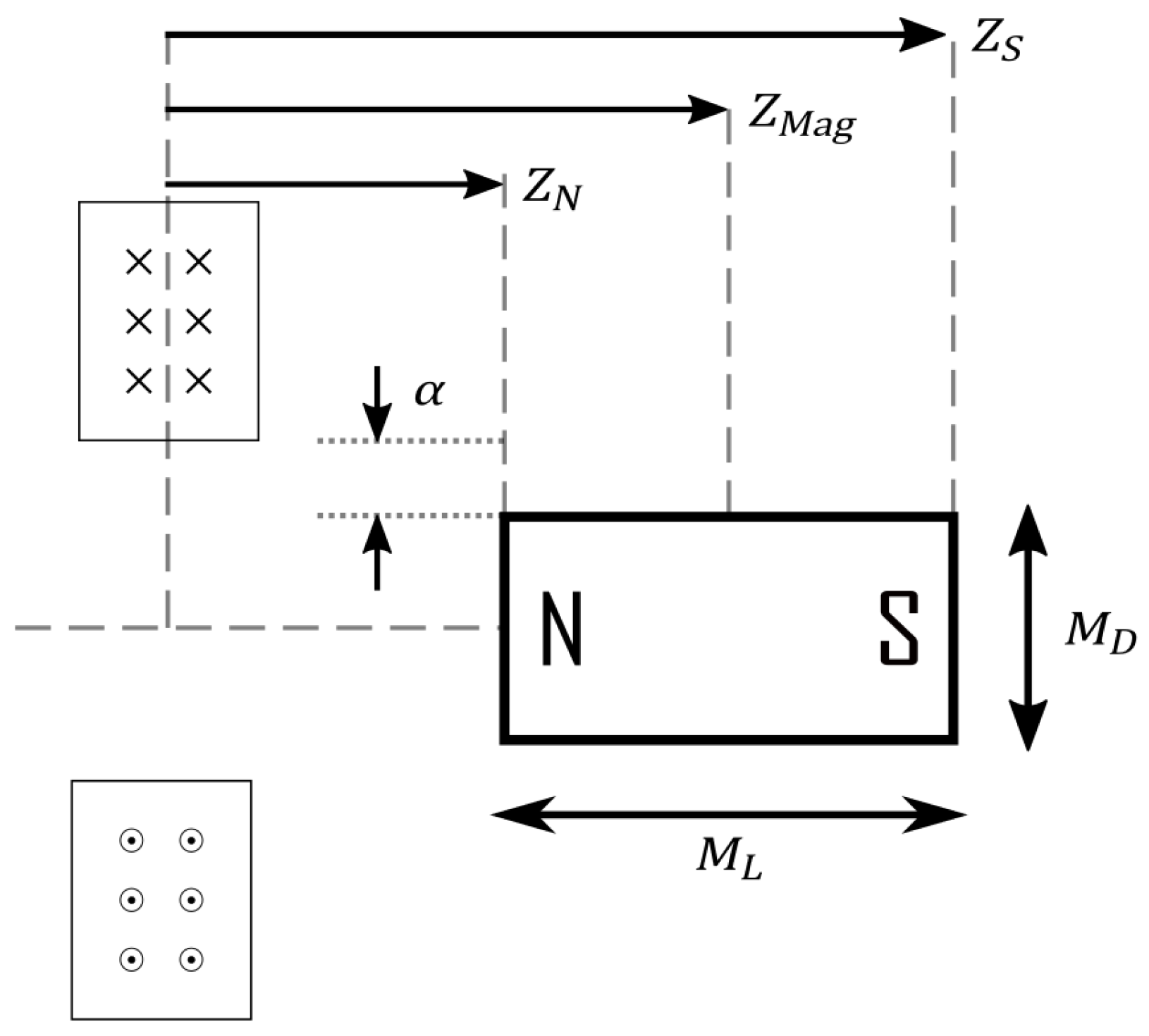
To understand how these actuators generate mechanical power, they first must be modelled. These electromagnetic linear actuators use a single coil made up of multiple turns of a conductor. When energized, this coil creates an electromagnetic field that interacts with the permanent magnet, creating either a positive or negative force depending on the polarity of the coil and magnet. This force can be used to create small displacements and generate mechanical power. A schematic diagram of these actuators is shown in
Figure 3. The force output of the actuator is characterised by the following Equation (
9).
where
is the remnant field of the magnet,
is the magnetic field produced by the magnet
and
is the permeability of free space. The magnetic field of the coil can be determined by taking the integral of the current loops of the coil along the axial length of the coil [
17,
18]. This results in Equation (
11)
where
Combining Equations (
5) and (
9) and summing the result for both the north (
) and south pole (
) of the magnet the resultant force can be calculated. The actuators parameters are shown in
Table 2 have been collected from the information reported by Zou et al. [
8]. These values are used to define the dimensions labelled in
Figure 3 which are required for the force calculations. These parameters results in the force profile(
) shown in
Figure 4. This plot shows the amount of force the actuator can generate at 1 amp for a displacement range from 0–5 mm. This shows that when the magnet is centred within the coil (0 mm displacement), the actuator cannot generate force. The mechanism zeroed where the actuator achieves peak force to maximise the force output for the entire stroke of the magnet. Required current to be applied to the actuators can thus be solved for a given force assuming there is an appropriate feedback mechanism that can determine the location of the magnet within the coil. Equation (
13) calculates the required coil current to generate the actuators force,
, given the force profile and location of the magnet.
The resulting voltage required for actuation can be calculated by Equation (
14) with the back emf of the actuator being calculated by the velocity of the magnet multiplied by
. Thus the instantaneous electrical power of the actuator can be calculated as
. This power can then be averaged over an entire flapping cycle to give a mean power consumption.
Utilising the parameters of the wing, actuator, mechanism and kinematics outlined in
Table 1 and
Table 2 the resulting moments generated by the wings and elastic mechanism can be calculated over a flapping cycle. Combined with the force model of the actuator, the current, back emf, voltage and power can be calculated. This simulation shows that with the mechanism and actuator reported by Zou et al. [
8] the average power consumption is calculated to be 1.17 W. This is compared to the approximate 1.2 W of power that was documented by the authors. This gives an actuator mechanical power efficiency of 0.34%. It is thus demonstrating that a significant amount of the electrical power delivered is being dissipated as heat. From the analysis of wing inertia and stiffness of the mechanism, it can be observed that the natural frequency of the system is much lower than the operating frequency. This causes a greater need for the actuator to accelerate and decelerate the wings each flapping cycle which requires a large amount of force at the times of the stroke when the velocity is the lowest. The low velocity and high force requirements translate to minimal developed mechanical power which is observed as a 30% increase in the mechanical power generated by the actuator.
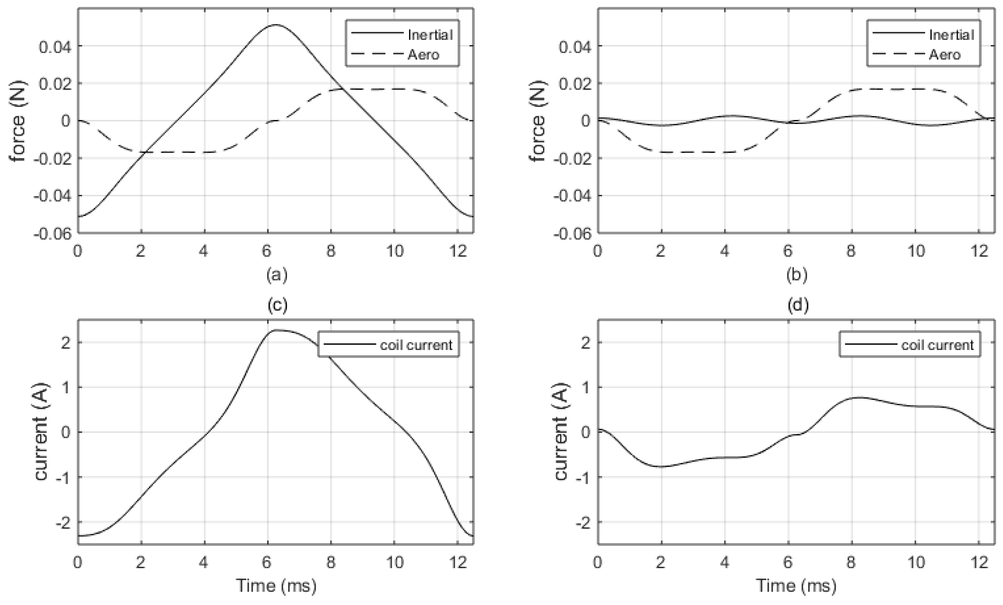
Figure 5a shows the calculated force the actuators is required to developed from the simulated aerodynamic and inertial moments that through a flapping cycle. This figure shows that with the low natural frequency, the peak force requirement from the inertial component is over twice that of the aerodynamic component. This causes the actuator to generate high forces that contribute to very little mechanical power yet dissipates large amounts of electrical power. The resonant case is also shown in
Figure 5b shows that the inertial component is almost completely removed. The only remaining component of this is due to the non-linear translation of the magnet actuator. This ensures that most of the mechanical power being developed is utilised by the aerodynamics of the system.
Figure 5c,d shows the electrical current profile of the two cases.
Figure 5c shows the electrical current is out of phase with the aerodynamic force and in phase with the inertial force shown in
Figure 5a. The resonance case shown in
Figure 5b,d shows that with the reduced inertial component the electrical current waveform is changed to become in phase with the aerodynamic damping. This change corresponds to a more efficient system that is able to convert a higher proportion of electrical power into aerodynamic power. This change has led the calculated input electrical power consumption to be reduced from 1.17 W to 0.155 W. This gives over a 7 times reduction in electrical power requirements. This is done by only decreasing the mechanical power requirement by 30%.
This work suggests that allowing an equivalent electromagnetic actuator to operate at resonance the input power consumption of the optimised system can be drastically reduced. When this is applied to the system presented by Zou et al. [
8] this corresponds to an input power requirement of approximately 13% of the original estimated power requirement. This brings the estimated input power density, in respects to the total craft mass, down from 15 kW/kg to 2 kW/kg. This is compared to the piezoelectric system by Jafferis et al., that had a system consuming 110–120 mW of power for a total vehicle mass of 259 mg [
2]. This gives an input power density of 420–460 W/kg, a difference of 4.2–4.7 times. This means that for a linear electromechanical actuator to have equivalent power density, it will require the efficiency of approximately 7%–8% up from 1.75% for the optimised version.
4. Power Electronics
Power electronics represent the interface between the actuator and the energy system. This is typically from a low voltage source such as a battery, supercapacitor or solar panel and is used to transform that energy to the required input for the actuator. For the piezoelectric actuators, the voltage needed to reach the desired strain levels is high, typically around 20,300 V [
2,
19]. To achieve these voltages a boost converter is required which requires several switching and magnetic components. This is then driving the actuators, which acts as a capacitative load. This creates losses as a significant amount of power is lost as reactive power. It was measured at 50–59 mW of reactive power compared to 26–35 mW of real power. This loss combined with the switching and magnetic component losses combined to create an overall efficiency of approximately 28% [
2]. However, this type of voltage generator has been selected as it consumes 37% of the power of an equivalent linear device [
19]. This efficiency has come at the cost of reduced payload capacity as the mass of the power electronics are significant. The overall weight of the electronics and control module for two piezoelectric actuators totalled 91 mg. This is compared to the mass of each actuator, which is estimated to be between 35–40 mg each.
The electrical requirements of a coil-based system are vastly different to that of a piezoelectric actuator. These actuators can be designed to operate at low voltages which are compatible to with sources typically available. The power electronics design is also simplified with the use of an H-bridge. This converts the DC supply to an AC source which can be used to control the actuator. The losses of these power electronics are proportional to the resistance of the gates used, which is typically very low. However, due to the losses of the actuator being dominated by ohmic losses, the additional power required to supply the system will be proportional to the resistance of the gate and the coil resistance. This applies to the resonant and non-resonant case. Utilising the same switching components from Jafferis et al. the EPC2036, the gate resistance is 73 m
and the coil resistance calculated to be approximately 530 m
. To complete the circuit, the current is required to flow through two of these gates doubling the resistance. This gives a ratio between the switch and actuator of 21.6%. Therefore with this configuration, approximately 21% more energy is required to meet the power requirements of the actuator. Changing to a lower resistant switch can further reduce this power consumption ( 10% w/ EPC2040 with
m
) but it is more efficient to increase the resistance ratio between the coil and switch. Changing the wire diameter is a method of tuning the required voltage of the coil. Halving the wire diameter and doubling the number of axial and radial turns maintains a constant actuator volume and approximate mass. This allows the actuator power consumption to remain the same with a significant decrease in current. Ohmic losses are not reduced by this due to the increase of coil resistance (up to 8.3
), but switch losses can be significantly decreased. The result of changing this ’winding ratio’ (
) is displayed in
Figure 6. with a significant decrease in the required current at the cost of an increased input voltage. This allows the switch to have an efficiency of approximately 98–99% for 73 and 30 m
switch respectively. This means that the components required for switching can be approximately 6 mg for the h-bridge with very high efficiency. The power electronics of the electromagnetic actuators can scale well as the design of the coil can be easily changed based on the actuation requirements. This design is the opposite of what is typical with piezo systems where the actuation size is limited due to the commercial availability of crystal thicknesses. This causes these actuator types to scale differently when building larger systems. It is expected if the electromagnetic actuator is scaled, the force production will scale with the volume of the actuator [
20]. Therefore, these actuators may be ideal for lower frequency systems that have significantly higher aerodynamic damping.
5. Analysis
A significant difference between piezoelectric and electromagnetic systems is that there is no mechanical limit to the power density that electromagnetics can achieve. For piezoelectric drives, the actuator energy density is defined by the strain limits and the generated blocked force [
21]. Electromagnetic actuators are instead thermally limited and must manage heat. Thus depending on the thermal capacity, the actuator will be able to deliver very high output power densities for short time periods. To remedy this, the overall efficiency and weight are assessed as critical parameters. An increase in system efficiency, given a set heat flow limitations, would increase the output power density.
The Output power density of the actuator is an important metric of performance. This has usually been calculated by taking the developed mechanical power and dividing it by the mass of the actuator. However, including the mass of the power electronics that is required for the actuator to operate is necessary to create a realistic power density. This can be applied to the piezoelectric system presented by Jafferis et al. [
2] with the reported flapping amplitude and frequency of
and 170 Hz, respectively. Taking the wing kinematics and design observed by Jafferis et al. [
2] the aerodynamic power can be estimated to be at 22–27 mW of mechanical power. This corresponds with the real power requirements that were documented [
2] and also accounting for the internal damping of the actuator [
3]. Using the estimated weight of the actuators, the output power density can be calculated as 275–385 W/kg. If the mass of the power electronics is included as it is not considered useful payload, the power density drops to 130–160 W/kg. The same calculation for the electromagnetic system presented in this work estimates 2.7 mW of mechanical power with the simulated coil weighing 52.5 mg, giving an actuator output power density of 52 W/kg. This can be increased by changing the conductive material from copper to a lower density wire such as copper clad aluminium (CCA). With copper having a density of 8.96 g/cm
and aluminium at 2.70 g/cm
a 15% copper CCA wire can have a relative density of approximately 40% compared to copper, this would decrease the mass of the actuator to at least 70% of the original, mass increasing the power density to over 75 W/kg. This power density is comparable to a fruit fly of 80 W/kg in regards to muscle mass [
4]. This means that not only are electromagnetic actuators comparable to insect flight muscles, but the performance gap between these actuators is also substantially reduced. Reducing the density of the conductor using in the coils is able to give the additional benefit of increasing the lift to mass ratio of the aircraft. This change in material has the ability to increase the calculated lift to mass ratio of the craft by 20%, from 0.94 to 1.22, meaning the input power requirement for hovering can also be reduced. The power expended in the resonant system is dependant on the aerodynamic damping of the system, a decrease in the amount of required mechanical power in a high loss system would cause the input requirements to drop by the square of the reduction. This would account for a further 40% decrease in input power requirements. This argues that if designing a FWMAV to operate at resonance, acknowledging the potential performance penalties [
14], electromagnetic actuators have a clear place with their power density and efficient power electronics. However, with a move away from resonance systems, electromagnetic actuators may be the only feasible choice for designers.
6. Conclusions
Linear electromagnetic actuators have been criticised for their high input power requirements when compared to other systems. We have shown that a combination of optimization of design and appropriate materials selection can allow these devices to approach the energy efficiency of piezo devices. We have also shown that a direct comparison of a bare electromechanical actuator and a piezo element is not reasonable, because the piezo element has inherent strain, and mechanical properties that incorporate resonance. With tuning for resonance, electromechanical actuators become very competitive, with advantages of design flexibility and the option to not be resonant when control is required. We have also shown that simple, low voltage, drive electronics of EMAs saves additional weight and reduces electrical losses compared to high voltage alternatives. Weight, power, efficiency and control must all be considered together for aerospace propulsion systems. We have shown that when all aspects are considered electromechanical actuators should be viable for flapping wing systems that emulate larger insects such as dragonflies.


