Article

Enhanced Flexible Algorithm for the Optimization of Slot Filling Factors in Electrical Machines †

by
Armin Dietz
1,
Antonino Oscar Di Tommaso
2,*,
Fabrizio Marignetti
3,
Rosario Miceli
2 and
Claudio Nevoloso
2
1
Technische Hochschule Nürnberg, Institut ELSYS, 90489 Nuremberg, Germany
2
Dipartimento di Ingegneria, University of Palermo, viale delle Scienze, Parco d’Orleans, 90128 Palermo, Italy
3
Department of electrical and Information Engineering (DIEI), University of Cassino and South Lazio, via. G. Di Biasio, 43, 03043 Cassino, Italy
*
Author to whom correspondence should be addressed.
This paper is an extended version of our paper published in: Caruso, M.; Di Tommaso, A.O.; Miceli, R.; Nevoloso, C. Algorithmic Approach for Slot Filling Factors Determination in Electrical Machines. In Proceedings of the 2018 7th International Conference on Renewable Energy Research and Applications (ICRERA), Paris, France, 14–17 October 2018; 1489–1494.
Energies 2020, 13(5), 1041; https://doi.org/10.3390/en13051041
Submission received: 14 January 2020 / Revised: 17 February 2020 / Accepted: 24 February 2020 / Published: 26 February 2020
(This article belongs to the Special Issue Advances in Rotating Electric Machines)

Abstract

:
The continuous development in the field of industrial automation and electric mobility has led to the need for more efficient electrical machines with a high power density. The improvement of electrical machines’ slot filling factors is one of the measures to satisfy these requirements. In recent years, this topic has aroused greater interest in the industrial sector, since the evolution of the winding technological manufacturing processes allows an economically sustainable realization of ordered winding arrangements, rather than random ones. Moreover, the manufacture of electrical machines’ windings must be preceded by an accurate design phase in which it is possible to evaluate the maximum slot filling factor obtainable for a given wire shape and for its dimensions. For this purpose, this paper presents an algorithmic approach for the evaluation of maximum slot filling factors in electrical machines under an ideal geometric premise. In particular, this algorithm has a greater degree of flexibility with respect to the algorithm approaches found in the literature, since the study has been extended to round, rectangular and hexagonal wire sections. Furthermore, the slot filling factor calculation was carried out both for standard and non-standard slots. The algorithmic approach proposed can be considered as an additional useful tool for the fast design of electrical machine windings.

1. Introduction

The development of more and more efficient electrical machines has become a topic of interest for various industrial sectors, such as automation or electric traction. In particular, high efficiency, high power density and cost-effective manufacturing are required in the automotive industry [1,2,3]. One possible solution to meet these requirements is to optimize the copper filling factor of stator winding [4,5,6,7,8,9,10,11]. In particular, a high copper filling factor involves a more rational and efficient use of copper with economic benefits and improved energy savings. Therefore, the optimization of the slot filling factor is a key focus in winding technology. The improvement of the slot filling factor depends mainly on the winding pattern schemes and the adopted winding manufacturing process. The simplest type of winding pattern is so-called “random winding”. In this case, the random winding process is sustainable for mass production and it is characterized by low manufacturing requirements. The main advantage is represented by its high production speed, while the disadvantages consist, generically, of lower filling factors. The highest possible filling factor is achieved by the “orthocyclic winding pattern” for round wires. This winding pattern presents a high packing density of wire, but the winding process is more complex and, therefore, more costly than the random winding process. In particular, the orthocyclic winding process requires very high manufacturing requirements to obtain an ordered wire positioning within each slot. Another possible winding pattern is the “layer winding”, where the wires are uniformly arranged in layers [12]. This winding pattern allows us to obtain higher filling factors than those of the random winding pattern. The choice of typology winding pattern depends on the functions and the design requirements of the electrical machine. Therefore, orthocyclic (or ordered) winding structures are appropriate for high power density applications.
In the past, the realization of commercial solutions that allow the economically sustainable manufacturing of distributed windings with ordered structures was very difficult due to the high economic burdens. The automated winding process technologies available for making distributed windings are: insertion winding technology, flyer winding technology and needle winding technology [13]. In recent years, these winding process technologies have undergone a great technological evolution that has allowed us to reduce manufacturing costs and winding process times with an ordered structure [13,14]. In [12], a new and innovative needle winding method that allows shifted layer winding structures for distributed round wire applications is described, thus significantly increasing the copper filling factor. In this regard, it is of considerable interest to accurately evaluate the slot filling factor obtainable during the design phase of electrical machines. In the previous century, this task was performed by means of manual graphic analysis or by testing the stator of the electrical machine during the pre-production phase. In order to carry out this process, the resources in terms of money, time and technical staff are not indifferent [15,16,17]. Therefore, a preliminary analysis of the maximum possible value of filling factor is an important step forward for the design of electrical machine windings for a given slot, wire shape and set of dimensions.
In the scientific literature, there are several definitions of slot filling factors and, generally, an electrical slot filling factor fcu and a mechanical slot filling factor fme are defined. In this study, the electrical slot filling factor fcu is given by the ratio between the total wire copper cross-section (Nw Acu) and the total slot cross-section Aslot. Furthermore, the mechanical slot filling factor fme is defined as the ratio between the total wire cross-section (Nw Aw) and the effective slot area Aeff, which is defined as the difference between the total slot cross-section Aslot and the area occupied by slot insulation. The two filling factors can be described by the following mathematical equations:
f c u = N w   A c u A s l o t
f m e = N w   A w A e f f
where Nw is the number of wires contained within a slot, Acu is the maximum copper cross-section of a single wire (useful cross-section) and Aw is the maximum cross-section of a single wire (including its insulation layer). For the purpose of this work, the electrical slot filling factor values are considered and discussed. This paper proposes an algorithmic approach for the preliminary determination of the slot filling factors. In particular, the goal of the present paper is to extend the work done in [18,19] with reference to various types of wires (this work also considers hexagonal cross-sections) and slots. Moreover, the identification of the best arrangement of wires within the slot for each slot type is suggested, with a technique aimed at the reduction of computation times. In fact, the algorithmic approach described in the previous papers calculates the slot filling factors only for circular and rectangular wire shapes. This algorithmic approach requires the definition of the coordinates of the first wire, that can be useful for the investigation of singular cases where the goal is the evaluation of the slot filling factors for a specific wire’s positioning. In fact, to research the best wire arrangement and, consequently, the highest obtainable values of the slot filling factors, the algorithm requires several executions of the procedure to obtain several values of the first wire position. Since each execution of the algorithm requires a few seconds, the time consumed can be significant.
However, the enhanced algorithm, here described, allows the determination of the maximum slot filling factor for a given slot, wire shape and set of geometrical dimensions. In particular, the algorithm procedure is designed in order to systematically investigate a large number of cases defined for several values of the coordinates of the first wire in order to optimize the computation time and find the best arrangement inside the slot, with an improved accuracy. In more detail, with a given cross-section geometry and given wire dimensions, the algorithm allows the calculation of the maximum number of wires that can be placed inside the slot. In this work, both wire and slot insulation are considered because, together, they cause a reduction of the useful slot area. In detail, with respect to the previous work, three different wire geometries, namely round, rectangular and hexagonal, are taken into consideration and the results are discussed. Since the use of hexagonal wires can present an innovative character in the design of electrical machines, attention has been paid to the comparative study of the filling factors obtainable with wires that have both circular and hexagonal cross-sections, by considering the same cross-section area.
This paper is structured as follows: Section 2 describes the state-of-the-art optimization algorithms of the slot filling factors, Section 3 describes the algorithmic approach proposed and Section 4 illustrates several cases of studies that have been carried out and the relevant obtained results.

2. State-of-the-Art Slot Filling Factor Optimization Algorithms

At the present time, the scientific literature does not include many works regarding the optimization of the slot filling factors with algorithmic approaches. Furthermore, the algorithmic approaches found in the literature refer to the case where the wire has a round cross-section. The optimal winding pattern is invariant with respect to the axis perpendicular to the stator cross-section. Therefore, the determination of the optimal winding pattern can be carried out with a bi-dimensional approach. A family of widespread algorithms is that of the orthocyclic windings algorithms (OWA). In [20], the results of this kind of algorithm are discussed. A study was carried out on the variation in the value of the mechanical and electrical slot filling factors when the radius of the circular conductor varies. In the first phase, the algorithm sets the coordinates of the center (xi; yi) of the first wire:
w i = ( x i y i ) .
Then, the wires of the same layer are plotted and the distance between the centers of two adjacent wires is equal to the diameter of the wire d. Once the first layer is finished, the wire coordinates of the upper layer are determined through the following relation:
w j = ( cos α sin α ) · d + w i
with α equal to 60° or 120° (Figure 1).
The algorithm ends when it is not possible to find a new wire position whose area intercepts the slot contour or its insulation contour; then, the slot is full.
Another algorithm approach, named the filling factor estimation algorithm (FFEA), is described in [15]. The goal of this algorithm is to reduce the design time of the winding by estimating the filling factors. In this case, the first wire is placed centrally at the slot bottom. The next wire is placed by checking all valid positions along a circle around the first wire, with a radius equal to the distance dw + tw, where dw and tw are the diameter of the wire and the safety distance or the minimum gap between two wires, respectively. For each new wire positioned, the algorithm checks whether there are overlaps with the contour of the slot, taking into account the presence of the slot insulation. If the new position is valid, the algorithm places the new neighbor wire and continues going around until all positions have been tried. The procedure ends when it is not possible to position wires that do not overlap the slot profile. The result of this algorithm is a random positioning of the wires forming the winding. Since the value of the determined filling factor depends on the initial position of the first wire, the procedure is repeated for several different initial positions.
Another interesting approach is described in [20]. This algorithm is based on the basic rules of the two algorithms described above. This algorithm is called the needle winding simulation algorithm (NWSA) because the objective is to optimize the positioning of each wire in order to simulate the process of needle winding. In this case, for the positioning of wire, a cost function is taken into consideration, accounting for the position and the downward force acting on the wires. In the algorithm, there are constraints to avoid overlapping between wires and between the wire and the slot profile. Optimal positioning is achieved by identifying the global minimum of the cost function. Authors use a genetic algorithm to search the global minimum in order to reduce convergence times.
Beyond the approaches described above, there are the dense packing algorithms, also called the wire inflation algorithms (WIA). The goal of these algorithms is to find the maximum radius of spheres within a given boundary and their corresponding coordinates when the number of spheres is fixed. In [21], an algorithm is described that simulates a system of billiard spheres within a limited space, whose radius is made to grow until it reaches a state whereby it becomes a blockade in the system. This algorithm approach is used for the dense packing of spheres in circular, triangular and hexagonal spaces [22,23,24]. This algorithm performs an event based on the physical simulation of a billiard system where the coordinates, the number and the speed of the spheres are set in advance as input data. Events are represented by the collision of each sphere with other spheres or with the borders of the system. Depending on the event type (either sphere–obstacle or sphere–sphere interaction) an elastic impact is performed, and the new velocities are calculated. At the increasing radii of the spheres, an eventual jamming occurs, resulting in a dense packing. For the purposes of maximizing the slot filling factor, the objective is to maximize the number of magnetic wires, with given radius, within the slot. In this sense, in [20], the authors, in order to make a comparison with the NWSA, have modified the described approach. In particular, the wires are understood to be charged particles exerting a Coulomb force on each other, leading to the movement of the spheres during the simulation. The results of the comparison are widely discussed.

3. Proposed Enhanced Algorithmic Approach

The basic rules of the algorithm proposed in this paper are mainly inspired by the approach proposed in [15] and the treatment of the winding patterns with ordered structures in detail [18]. The algorithm is based on a general approach that is valid for different stator slots and for different wire shapes. In detail, for round and hexagonal wires, the algorithm focuses on the windings, with orthocyclic arrangement of the wires within the slot. Moreover, the algorithm has been designed so as to be able to define some critical aspects, such as the possible presence of slot insulation, the positioning of the wire parallel to the flank or to the bottom of the slot, any safety distances between the wires forming the winding and a large number of the possible coordinates of the first wire. In this way, the algorithm presents a high degree of flexibility that makes investigating the maximum slot filling factors obtainable in many cases of study. The algorithm has been implemented in the Matlab environment and it is described in detail below.

3.1. Slot Geometrical Features Definition

Compared to the works found in the literature, where simplified models of slot have been taken into account, in this work, both a standard slot (STSL) model and the non-standard (NSTSL) ones are used. The slot profiles are defined with the presence of an insulation sheet and, therefore, its thickness dins is taken into account. In general, the slot insulation sheet is pre-folded and does not substantially modify the slot cross-section profile available for the positioning of the wires. The geometries and the related contour data of a standard slot, typically used for wires, and a non-standard one are shown in Figure 2a,b [16], respectively.
Generally, the slot profiles are supplied with CAD drawings by the manufacturers and, therefore, the geometrical parameters are easily determined. The dimensions of each slot are known and are reported in Table 1 and Table 2.
The slot profiles are defined in the xy reference frame by means of characteristic points connected by lines and arcs. The implementation of the geometric model of the slot profile is carried out as described in [18]. The cross-sections of slots are calculated in a numeric way by the trapezium rule in the same way as [15]. In particular, the slot areas are divided into different sections whose characteristic points are known (Figure 3a,b). The calculated cross-sections show a maximum deviation of less than one percent from the cross-section given by the specifications.

3.2. Magnet Wire Data

In this study, investigations into round, rectangular and hexagonal wires have been carried out. The geometrical data of the round and rectangular wires used in this paper are obtained from [25,26]. By these standards, the nameplate data, the insulation degree, tolerances and maximum dimensions allowed for each wire shape are reported. For rectangular shapes, the standard defines the shape of the wire with rounding corners. However, there is not an international standard for hexagonal wires. The use of the latter could be an innovative idea, as they can substantially improve the filling factors. Improvements must be compared with the production costs which, compared to the past, have been reduced thanks to the technological evolution of wire manufacturing processes [13,17]. Therefore, the geometric data of the hexagonal wires will be hypothesized. The geometrical reference quantities for each wire shape are defined below for:
1.
Round wire geometrical data:
  • dcu diameter wire without insulation;
  • dmax maximum diameter of wire with insulation;
  • xc and yc coordinates of wire center.
2.
Rectangular wire geometrical data:
  • L1cu width of the rectangular wire without insulation;
  • L2cu height of the rectangular wire without insulation;
  • L1max maximum width of the rectangular wire with insulation;
  • L2max maximum height of the rectangular wire with insulation;
  • rcorner corner radius;
  • xc and yc coordinates of the wire center.
3.
Hexagonal wire geometrical data:
  • rcu radius of circumference circumscribed to the hexagon without insulation;
  • rmax maximum radius of circumference circumscribed to the hexagon with insulation;
  • xc and yc coordinates of the wire center.
  • phi (ϕ) rotation angle of the hexagon.
Figure 4 shows the wire cross-sections with the related contour data.

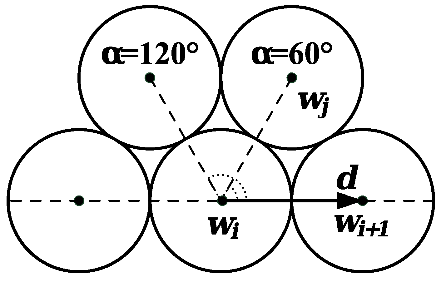
3.3. Constraints for Wire Distribution and Placement

In the algorithm, the slot models have been implemented in a xy plane with the bottom or the ground of each slot parallel to the y-axis. Each slot profile has been divided into several reference sections Figure 3a,b. These sections are referred to a one-half slot. The distribution and placement conditions of wires are defined for each section and applied in a specular way for each half of the slot. In order to avoid overlapping between the wire and the slot profile and between adjacent wires, several constraints are taken into account. Therefore, for each wire that must be positioned within the slot profile, the following gaps are considered and investigated:
  • distance between the wire and a part (arc or line) of the slot insulation sheet profile;
  • distance between the new wire and an existing wire.
In Figure 5, the distances between the slot profile and the round and rectangular wires are shown. In each region of the slot profile, the minimum value of the various distances is evaluated. In particular, for round wires, the distances are defined with respect to the center of the wire and it is imposed that
m i n { | d 1 | , | d 2 | , , | d n | } r m a x ,
whereas, in the case of rectangular and hexagonal wires, these distances are evaluated with respect to the vertices of each wire shape (Figure 6) and it is imposed that
m i n { | d 1 | , | d 2 | , , | d n | } 0 .
Regarding the distance between wires, it is possible to add an additional safety distance tw. The winding positioning pattern adopted in this work is the orthocyclic one that can be obtained in the case of round and hexagonal wires. However, an ordered arrangement was taken into consideration for rectangular shaped wires. Moreover, it is possible to vary the angle formed between the line joining the centers of the wires and the horizontal one of the xy plane (Figure 7). In this case, the new arrangement is obtained by applying the following coordinate transformation to the center of wires for round wires, and also to the vertices for rectangular and hexagonal wires:
( x i n e w y i n e w ) = ( cos β sin β sin β cos β ) ( x i y i ) .
In this sense, it is possible to evaluate the value of the slot filling factors in the case where the wires are arranged parallel to the flank or the bottom of the slot. This study has been performed with particular attention paid to round and rectangular wires since. in the hexagonal wire case, as described above, it is possible to set the rotation angle.

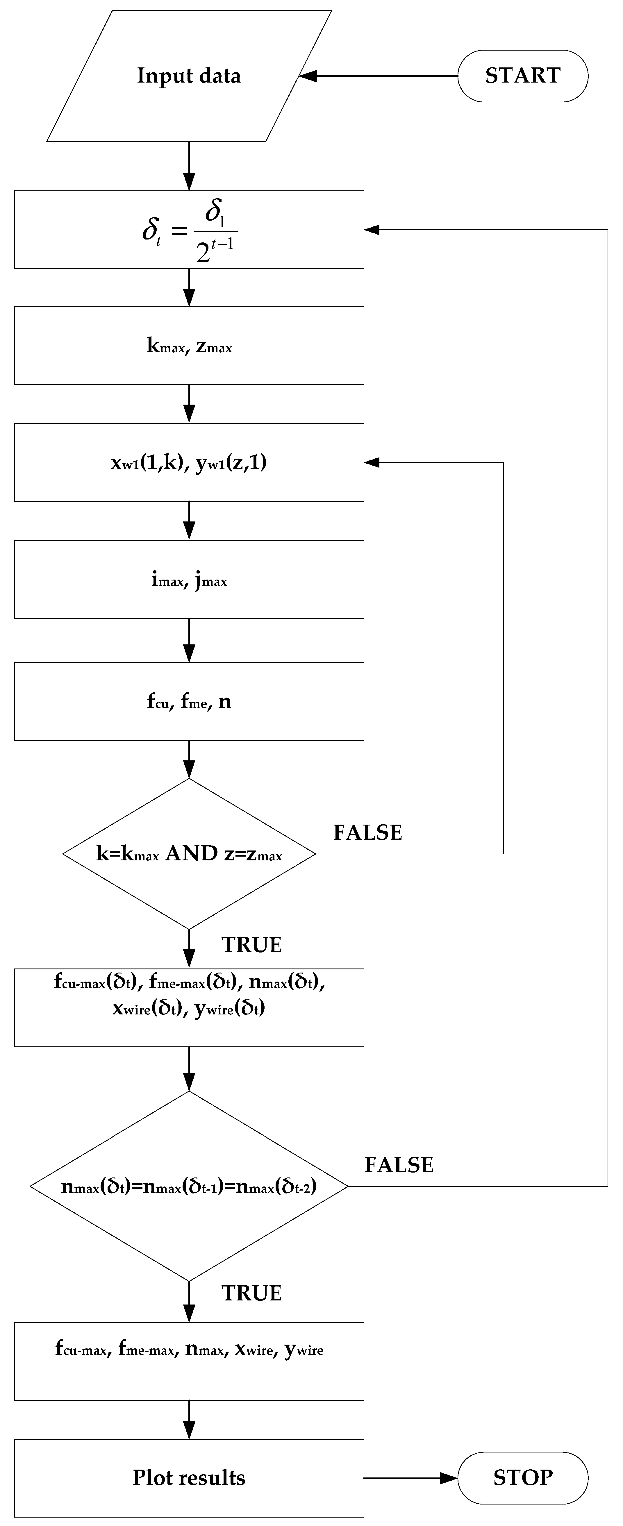
3.4. The Algorithm Procedure

As described above, the algorithm has been designed to automatically define several positions for the first wire. In this procedure, the position of the first wire is defined by its center (xw1, yw1), which it is selected in such a way that it will be located in the region of space near the lower wedge of the slot (i.e., in the lower rounded corner):
x w 1 = x i n i t + d i n s
y w 1 = y i n i t + d i n s w 2
where dins, xint, yint are the slot insulation foil thickness and the initial wire coordinates, respectively, which are chosen in such a way as to avoid overlaps with the slot profile. In order to evaluate the filling factors, several pairs of values of xint, yint are assigned. For this purpose, it is necessary to evaluate the extremes of the range, within which the initial coordinates must vary. These extremes depend on the slot geometry and the wire geometrical features. In more detail, since the slot geometry is specular with respect to the x-axis (see Figure 3) and the first wire is positioned in the region of space near the lower wedge of the slot, the lower extremes are chosen in such way that they are tangent with the lower slot wedge profile, whereas the upper extremes of the range are chosen so that an additional increase in the initial coordinates causes the loss of significant useful wires. Therefore, in the case of circular, hexagonal and rectangular shapes located in the STSL model, the extremes are respectively equal to:
( 10 ) x i n i t _ c i r c / h e x m i n = d m a x / 2 x i n i t _ c i r c / h e x m a x = 3 2 d m a x ( 11 ) y i n i t _ c i r c / h e x m i n = d m a x / 2 y i n i t _ c i r c / h e x m a x = y B + 3 2 d m a x d i n s + w 2 ( 12 ) x i n i t _ r e c t m i n = L 1 m a x / 2 x i n i t _ r e c t m a x = 3 2 L 1 m a x ( 13 ) y i n i t _ r e c t m i n = L 2 m a x / 2 y i n i t _ r e c t m a x = y B + 3 2 L 2 m a x
where yB is the y-coordinate of the characteristic point B (Figure 3a). On the other hand, for NSTSL, the extremes are equal to, respectively:
( 14 ) x i n i t _ c i r c / h e x m i n = d m a x / 2 x i n i t _ c i r c / h e x m a x = 3 2 d m a x ( 15 ) y i n i t _ c i r c / h e x m i n = d m a x / 2 y i n i t _ c i r c / h e x m a x = 3 2 d m a x ( 16 ) x i n i t _ r e c t m i n = L 1 m a x / 2 x i n i t _ r e c t m a x = 3 2 L 1 m a x ( 17 ) y i n i t _ r e c t m i n = L 2 m a x / 2 y i n i t _ r e c t m a x = 3 2 L 2 m a x
The evaluation of the filling factors, when the first wire center position (xw1, yw1) varies, is carried out by using two loops with indices k and z, with maximum values kmax and zmax. They are calculated by the following relationships:
k m a x = c e i l ( x i n i t m a x x i n i t m i n δ t )
z m a x = c e i l ( y i n i t m a x y i n i t m i n δ t )
where ceil(x) is a function that rounds x to the nearest integer greater or equal to x and δt is the variation step of the initial coordinates. The last quantity starting value δ1 is chosen at least 1/50 of the maximum dimension of the considered wire (dmax for the circular case, L2max for the rectangular case and 2rmax for the hexagonal case). In this way, the first wire center position (xw1, yw1) varies according the following relationships:
x w 1 ( 1 , k ) = x i n i t m i n + d i n s + δ t · ( k 1 )
y w 1 ( z , 1 ) = y i n i t m i n + d i n s w 2 + δ t · ( z 1 )
Furthermore, in order to investigate the possibility of finding a better wires arrangement when δt varies, several iterations with a progressive halving of δt are performed until to the maximum value of the number of wires positioned nmax presents the same value for three consecutive iterations. Obviously, this choice determines the increasing of computational time, but a more accurate research of the maximum filling factors.
In order to place the next wires, the cross-section of the slot is divided into a grid formed by i columns and j rows, where both the first column and the first row are defined as starting from the first wire position. The maximum number of columns imax and rows jmax is calculated according to the slot and wire dimensions. For round, rectangular and hexagonal wires these values are calculated by means of the following relationships, respectively:
i m a x = r o u n d ( h 3 2 d m a x )
j m a x = r o u n d ( w d m a x )
i m a x = c e i l ( h L 1 m a x )
j m a x = c e i l ( w L 2 m a x )
i m a x = c e i l ( h 3 2 r m a x )
j m a x = c e i l ( w 3 2 r m a x )
where round(x) is a function that rounds each element of x to the nearest integer. The distribution of the wires occurs through two loops that change the indices i and j in order to position the wires along with the whole slot profile. In the cases of the round and hexagonal wires, in order to obtain an orthocyclic winding pattern, the coordinates of the successive wire are calculated as previously described in Section 2. The rectangular case is widely described in [13]. The positioning of the wires is considered valid only if it meets the overlapping conditions described above. The algorithm calculates, for each possible pair of coordinates (xw1(1,k) yw1(z,1)), the number of positioned wires n, the electrical and mechanical slot filling factor values fcu and fme and the coordinates of the positioned wires (xwire, ywire). In this way, each of the quantities of interest is represented by an array, in which each element is associated to the coordinates of the first positioned wire. The search for the best wire arrangement for a fixed wire shape, its geometric dimension, type of positioning and slot profile can be achieved by identifying the maximum value of number of wires positioned nmax within the array. This procedure, as mentioned above, is repeated until the quantity, nmax(δt), presents the same value for three consecutive δt values. Therefore, once the coordinates of the first wire (xw1, yw1) associated to the best wire arrangement is determined, the algorithm provides a graphical representation of the slot containing the wires. Furthermore, the coordinates of the positioned wires (xwire, ywire) are available and the manufacturer has the ability to know and choose a reference wire for the production phase according to the winding technological process adopted. In short, the algorithm works via the following steps:
  • The algorithm asks for, as input data, the wire shape, the type of positioning and the slot profile to be used;
  • The geometric dimensions of the wire and the slot and the value of the safety distance are defined in an input file;
  • The algorithm proceeds by plotting the slot profile;
  • Subsequently, the algorithm proceeds to position the wires; for fixed coordinates of the first wire, for each of them, it checks the overlapping conditions and calculates the number of positioned wires and the value of the electrical and mechanical filling factors;
  • The algorithm repeats the evaluation procedure for each possible pair of the initial wire coordinates and generates an array for each quantity of interest;
  • It searches the best wire arrangement case (characterized by nmax wires per slot, fcu-max and fme-max) and their corresponding coordinates to the first wire;
  • The algorithm repeats the procedure until to the maximum value of the number of wires positioned nmax presents the same value for three consecutive δt values;
  • Finally, from the knowledge of the first wire position, the algorithm proceeds by plotting the slot profile containing the wires and provides, in an output, the maximum number of positioned wires nmax, the best values of the electrical and mechanical slot filling factors fcu-max and fme-max and the coordinates of all positioned wires (xwire, ywire).
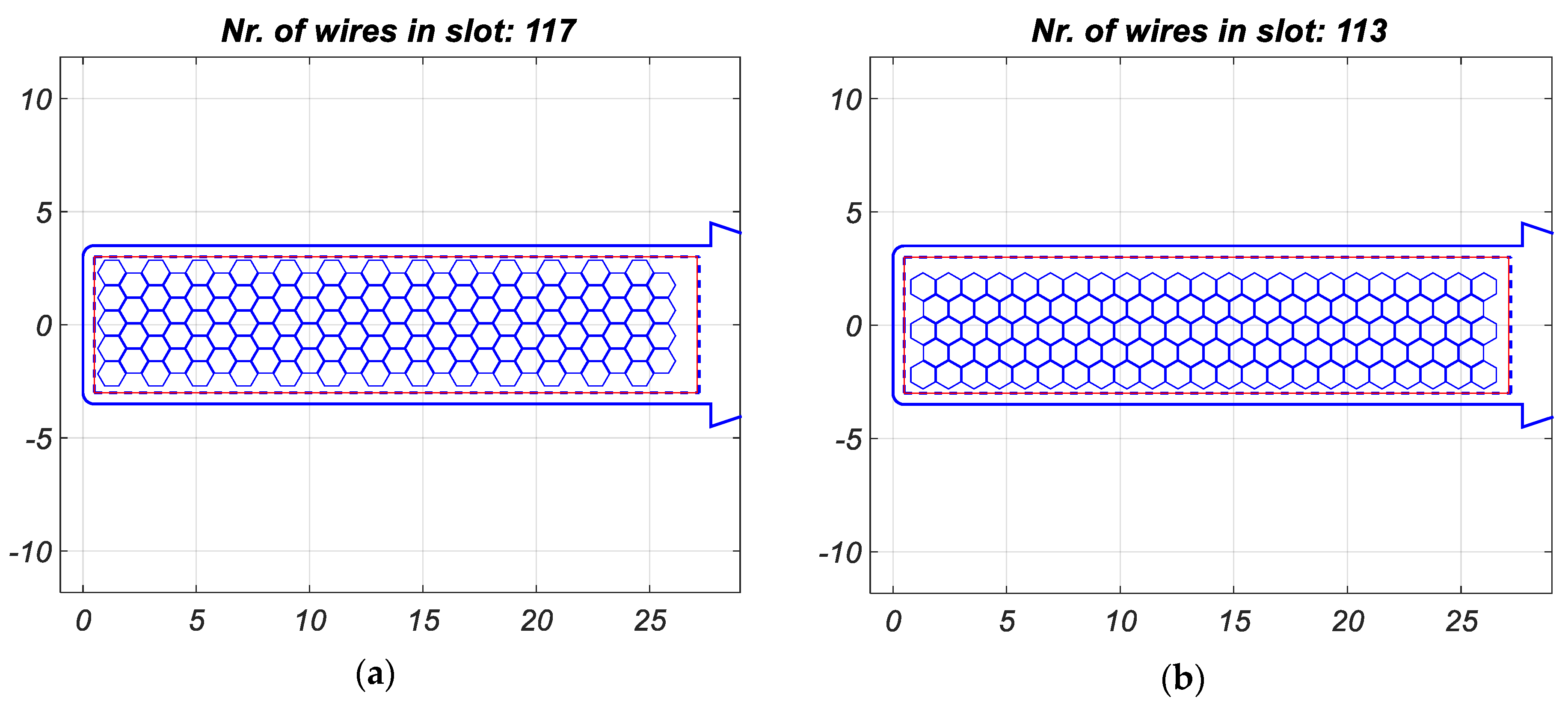
In addition, for an accurate description and understanding, the algorithm flowchart is reported in Figure 8.

4. Cases of Study

In order to validate the proposed algorithm, several cases of study have been performed. This study has been carried out both for the STSL and for the NSTSL and for each wire shape. From international standards [25,26], it is possible to deduce the nominal dimensions, the insulation grades, the tolerances and the outer maximum dimensions for each typology of wire. In this work, the largest allowed outer dimensions are adopted to consider the worst case for the evaluation of the slot electrical filling factor. An insulation grade (According to [25,26] the grade is defined as “the range of thickness of the insulation wire”.) 3 and a grade 2 for the round-shaped wire and for the rectangular-shaped one have been taken into consideration, respectively. The dimensions of the hexagonal wire have been deduced, assuming the cross-section is equal to that of the round wire. In this way, it is possible to compare the slot filling factors and evaluate the benefits derived from the use of hexagonal wires. In this study, six different dimensions have been chosen for each wire shape, respectively. For each dimension, three additional interspaces tw, respectively equal to 0, 0.05 and 0.1 mm, were taken into consideration. Furthermore, regarding the standard slot, a study was carried out on the possibility of positioning the wires parallel to the ground or the bottom (PG) and to the flank (PF) of the slot. The dimensions of the wires, used for this study and expressed in mm, are reported in Table 3 and Table 4.
Figure 9, Figure 10, Figure 11 and Figure 12, it is possible to notice how the algorithm returns the slot profile with the desired distribution of the wires and also shows the number of inserted wires. In particular, in the case of round wires, the winding pattern presents an orthocyclic structure where the positioning is parallel to the bottom in one case and parallel to the flank of the slot in the other case. In the case of rectangular wire, the winding pattern is ordered. In the case of the hexagonal wire, an orthocyclic winding pattern is obtained, both with phi equal to zero and with phi equal to π/2. Furthermore, it is possible to notice how the structure remains ordered with the use of an additional interspace tw.
In Figure 13, the value of slot electrical filling factors obtained for the case of the round wire, with a parallel bottom disposition, both for the STSL and the NSTSL, are reported. A comparison, between the slot electrical filling factors obtained with a parallel bottom disposition and the one obtained with the parallel flank disposition of the standard slot, are reported in Figure 14. This comparison shows that the slot electrical filling factor is higher for a parallel flank disposition for each additional interspace tw. A similar study was performed for rectangular wires. Figure 15 shows the trend of slot electrical filling factors as a function of the cross-section area. On average, the filling factors obtained in the rectangular case are higher than those of the round case for the dimensions chosen. Additionally, in the rectangular case, the slot electrical filling factor is higher in a parallel flank disposition (Figure 16). In this work, the comparison between the slot electrical filling factors obtained in the round and rectangular wire cases, with equal cross-section, has not been reported because it has been widely discussed in [18] and in [19]. Furthermore, the rectangular wires are used for medium and high-power applications, whereas the round ones are mostly used for low-power applications. Figure 17 and Figure 18 show the comparison between the value of electrical slot filling factors obtained for hexagonal wires with phi (ϕ) equal, respectively, to 0 and π/2. This study is performed both for the standard slot and for the non-standard slot, for each value of the additional interspace tw. In the standard slot, the slot electrical filling factors are higher when phi = 0 whereas, in the non-standard slot, in some cases, higher electrical slot filling factors are obtained with phi = π/2. Particularly interesting is the comparison between the slot filling factors obtained in the case of the round wire and the hexagonal one, with the same cross-section. In Figure 19, the comparison between the slot electrical filling factors of round wires with the parallel flank disposition and the slot electrical filling factors of hexagonal wires with phi = 0, is reported. From this comparison, it can be seen that the filling factors obtained in the case of hexagonal wires are always higher than those obtained in the case of round wires. This difference decreases as the additional interspace increases. Therefore, the use of hexagonal wires can provide innovation in the field of electrical machine windings. Obviously, this improvement must be contextualized with any additional costs and the current state-of-the-art of specially shaped wire manufacturing process. Furthermore, with the choice of δ1, equal to 1/50 of the maximum dimension of the considered wire, the worst-case scenario of the study has presented a computation time equal to about 10 min, corresponding to about 8000 different first wire positions. In order to validate the choice of δ1 equal to 1/50, further investigations have been carried out, both increasing and decreasing the value of δ1.
In more detail, values of δ1 smaller than 1/50 only provide longer computational times with the identification of the same best wire arrangements. On the contrary, in almost all analyzed cases, the values of δ1 in the range from 1/50 to 1/25 allow us to identify the same best wire arrangements with shorter computational times compared to those obtained with δ1 being equal to 1/50. Values of δ1 lower than 1/25 generate longer computational times due the higher number of δi iterative variations. Therefore, the choice of δ1 equal to 1/50 of the maximum dimension of the wire under study provides a good compromise between computation time and identification of the optimal wire arrangements.
The case studies shown here demonstrate how the algorithm allows us to accurately estimate the best value of the filling factors and reveal that it is a useful tool for the design of electrical machine windings. The results, like electrical filling factors, are calculated under the assumption of the ideal geometric shape of each wire and slot filling paper. For practical considerations, tolerances of shape and diameter must be taken into account; also, the winding process itself does not give an ideal orthocyclic winding distribution in the slot. This deviations from ideal geometry and winding process can be considered using additional geometric tolerances. With the given algorithm, the influence of non-ideal conditions on the filling factor and maximal turns can be calculated within a few minutes and motor design engineers and process engineers can make decisions based on a reliable calculation concept.

5. Conclusions

High filling factors make it possible to improve electrical machines’ performances, meeting the design requirements of several application fields. This improvement requires an optimal arrangement of the wires inside the slots and a careful evaluation of the maximum slot filling factor obtainable in the design phase. In this paper, an algorithm approach is proposed to perform the calculation of slot filling factors in electrical machines. The algorithm requires, as input data, the geometrical data of the slot, the insulation thickness, the shape of the wire, the dimensions of the wire and the type of disposition inside the slot. From this data, the algorithm determines the maximum slot filling factors, the number of wires positioned, a graphic distribution of the wires inside the slot and the coordinates of the wires positioned. The algorithm has a high degree of flexibility and requires a reasonable computation time (about 10 min in the worst case). The conducted study proves that the algorithm is very simple and can give useful results in the designing processes of winding layouts. Furthermore, the algorithm can be used as investigation tool because it allows us to compare electrical filling factor values when different wire shapes with the same cross-section are employed. From the investigations here presented, it has been shown that the use of hexagonal wires provides higher filling factors than those obtained with the use of round wires. Although the comparison between the slot filling factors obtainable with rectangular wires and hexagonal wires with the same wire cross-section is not presented in this paper, the use of hexagonal wires allows us to obtain higher filling factors than those obtained with the use of rectangular wires. This result is due to the orthocyclic arrangement of the hexagonal wires that optimally occupy the slot area, unlike the ordered arrangement of the rectangular wires. Non-ideal geometry of the magnetic wires and the tolerances of the winding process can be easily considered using additional geometric factors and practical problems can be addressed. These results may be of considerable interest in the optimization of electrical machine windings. Future developments will concern the extension of this study to a greater number of cases in terms of slots and an in-depth study on the producibility of hexagonal wires. In particular, the evaluation of the effects of real cross-section deviation with respect to ideal deviation should be modelled and implemented in future research. Furthermore, experimental investigations will be conducted in order to validate the algorithm results.

Author Contributions

Authors contributed equally to this work. Authors of this manuscript jointly conceived the theoretical developments, revised the state-of-the-art algorithms and provided suggestions to obtain a flexible algorithm for the optimization of slot filling factors in the design phase of electrical machines. All authors have read and agreed to the published version of the manuscript.

Funding

This research received no external funding.

Acknowledgments

This work was financially supported by MIUR—Ministero dell’Istruzione dell’Università e della Ricerca (Italian Ministry of Education, University and Research) and by SDESLab—Sustainable Development and Energy Saving Laboratory of the University of Palermo.

Conflicts of Interest

The authors declare no conflict of interest.

References

  1. You, Y.-M. Optimal Design of PMSM Based on Automated Finite Element Analysis and Metamodeling. Energies 2019, 12, 4673. [Google Scholar] [CrossRef] [Green Version]
  2. Caruso, M.; di Tommaso, A.O.; Lombardo, M.; Miceli, R.; Nevoloso, C.; Spataro, C. Maximum Torque Per Ampere control algorithm for low saliency ratio interior permanent magnet synchronous motors. In Proceedings of the 2017 IEEE 6th International Conference on Renewable Energy Research and Applications (ICRERA), San Diego, CA, USA, 5–8 November 2017; pp. 1186–1191. [Google Scholar]
  3. Caruso, M.; di Tommaso, A.O.; Miceli, R.; Nevoloso, C.; Spataro, C.; Trapanese, M. Maximum Torque per Ampere Control Strategy for Low-Saliency Ratio IPMSMs. Int. J. Renew. Energy Res. 2019, 9, 374–383. [Google Scholar]
  4. L-Refaie, A.M.E. Fractional-slot concentrated-windings synchronous permanent magnet machines: Opportunities and challenges. IEEE Trans. Ind. Electron. 2010, 57, 107–121. [Google Scholar] [CrossRef]
  5. Schiefer, M.; Doppelbauer, M. Indirect slot cooling for high-power-density machines with concentrated winding. In Proceedings of the 2015 IEEE International Electric Machines Drives Conference (IEMDC), Coeur d’Alene, ID, USA, 10–13 May 2015; pp. 1820–1825. [Google Scholar]
  6. Hofmann, B.; Bickel, B.; Bräuer, P.; Leder, M.; Franke, J. Theoretical benefits of powder-coating based insulation layers regarding copper fill factor in electric drives. In Proceedings of the 2016 6th International Electric Drives Production Conference (EDPC), Nuremberg, Germany, 30 November–1 December 2016; pp. 172–176. [Google Scholar]
  7. Kulan, M.C.; Baker, N.J.; Widmer, J.D. Design of a high fill factor permanent magnet integrated starter generator with compressed stator windings. In Proceedings of the 2016 XXII International Conference on Electrical Machines (ICEM), Lausanne, Switzerland, 4–7 September 2016; pp. 1513–1519. [Google Scholar]
  8. Fyhr, P.; Domingues, G.; Reinap, A.; Andersson, M.; Alaküla, M. Performance and manufacturability tradeoffs of different electrical machine designs. In Proceedings of the 2017 IEEE International Electric Machines and Drives Conference (IEMDC), Miami, FL, USA, 21–24 May 2017; pp. 1–7. [Google Scholar]
  9. Torreggiani, A.; Bianchini, C.; Davoli, M.; Bellini, A. Design for Reliability: The Case of Fractional-Slot Surface Permanent-Magnet Machines. Energies 2019, 12, 1691. [Google Scholar] [CrossRef] [Green Version]
  10. Cheng, L.; Sui, Y.; Zheng, P.; Yin, Z.; Wang, C. Influence of Stator MMF Harmonics on the Utilization of Reluctance Torque in Six-Phase PMA-SynRM with FSCW. Energies 2018, 11, 108. [Google Scholar] [CrossRef] [Green Version]
  11. Caruso, M.; Di Tommaso, A.O.; Marignetti, F.; Miceli, R.; Ricco Galluzzo, G. A General Mathematical Formulation for Winding Layout Arrangement of Electrical Machines. Energies 2018, 11, 446. [Google Scholar] [CrossRef] [Green Version]
  12. Stenzel, P.; Dollinger, P.; Richnow, J.; Franke, J. Innovative needle winding method using curved wire guide in order to significantly increase the copper fill factor. In Proceedings of the 2014 17th International Conference on Electrical Machines and Systems (ICEMS), Hangzhou, China, 22–25 October 2014; pp. 3047–3053. [Google Scholar]
  13. Hagrn, J.; Blanc, F.S.-L.; Fleischer, J. Handbook of Coil Winding, Technologies for Efficient Electrical Wound Products and Their Automated Production; Springer: Berlin, Germany, 2017. [Google Scholar]
  14. Gerngroß, M.; Herrmann, P.; Westermaier, C.; Endisch, C. Highly flexible needle winding kinematics for traction stators based on a standard industrial robot. In Proceedings of the 2017 7th International Electric Drives Production Conference (EDPC), Würzburg, Germany, 5–6 December 2017; pp. 1–7. [Google Scholar]
  15. Raabe, N. An algorithm for the filling factor calculation of electrical machines standard slots. In Proceedings of the 2014 International Conference on Electrical Machines (ICEM), Berlin, Germany, 2–5 September 2014; pp. 981–986. [Google Scholar]
  16. Richter, R.; Brüderlink, R. Elektrische Maschinen; Springer: Berlin/Heidelberg, Germany, 1954; Volume 4. [Google Scholar]
  17. Jaksic, D. Getting rid of the air, or how to maximize winding fill factor (ID 81). In Proceedings of the 2011 1st International Electric Drives Production Conference, Nuremberg, Germany, 28–29 September 2011; pp. 84–87. [Google Scholar]
  18. di Tommaso, A.O.; Genduso, F.; Miceli, R.; Nevoloso, C. Fast procedure for the calculation of maximum slot filling factors in electrical machines. In Proceedings of the 2017 Twelfth International Conference on Ecological Vehicles and Renewable Energies (EVER), Monte Carlo, Monaco, 11–13 April 2017; pp. 1–8. [Google Scholar]
  19. Caruso, M.; di Tommaso, A.O.; Miceli, R.; Nevoloso, C. Algorithmic Approach for Slot Filling Factors Determination in Electrical Machines. In Proceedings of the 2018 7th International Conference on Renewable Energy Research and Applications (ICRERA), Paris, France, 14–17 October 2018; pp. 1489–1494. [Google Scholar]
  20. Herrmann, P.; Stenzel, P.; Vögele, U.; Endisch, C. Optimization algorithms for maximizing the slot filling factor of technically feasible slot geometries and winding layouts. In Proceedings of the 2016 6th International Electric Drives Production Conference (EDPC), Nuremberg, Germany, 30 November–1 December 2016; pp. 149–155. [Google Scholar]
  21. Lubachevsky, B.D. How to simulate billiards and similar systems. J. Comput. Phys. 1991, 94, 255–283. [Google Scholar] [CrossRef] [Green Version]
  22. Graham, R.; Lubachevsky, B.; Nurmela, K.; Östergård, P. Dense packings of congruent circles in a circle. Discret. Math. 1998, 181, 139–154. [Google Scholar] [CrossRef] [Green Version]
  23. Graham, R.L.; Lubachevsky, B.D. Dense packings of equal disks in an equilateral triangle: From 22 to 34 and beyond. Electr. J. Comb. 1995, 2, 1–39. [Google Scholar]
  24. Lubachevsky, B.D.; Graham, R.L. Curved hexagonal packings of equal disks in a circle. Discret. Comput. Geom. 1997, 18, 179–194. [Google Scholar] [CrossRef] [Green Version]
  25. The National Standards Authority of Ireland. IEC 60317-0-1 Specifications for Particular Types of Winding Wires Part 0-1: General Requirements- Enamelled Round Copper Wire; NSAI: North Wood, Ireland, 2014. [Google Scholar]
  26. The National Standards Authority of Ireland. IEC 60317-0-2 Specifications for Particular Types of Winding Wires Part 0-2: General Requirements- Enamelled Rectangular Copper Wire; NSAI: North Wood, Ireland, 2014. [Google Scholar]
Figure 1. Round wires with orthocyclic distribution.
Energies 13 01041 g001
Figure 2. Cross-section of the standard slot (a) and non-standard slot (b) with contour parameters.
Energies 13 01041 g002
Figure 3. Half cross-section of the standard slot (a) and non-standard slot (b) divided into sections.
Energies 13 01041 g003
Figure 4. Wire cross-sections with contour data.
Energies 13 01041 g004
Figure 5. Distances between the wires and the slot profile.
Energies 13 01041 g005
Figure 6. Characteristic points of the rectangular and hexagonal wires.
Energies 13 01041 g006
Figure 7. Rotation of the orthocyclic distribution.
Energies 13 01041 g007
Figure 8. Algorithm flowchart.
Energies 13 01041 g008
Figure 9. Orthocyclic distribution of the round wires with the parallel ground disposition (a) and with the parallel flank disposition in the standard slot (b) (tw = 0 mm, dmax = 1.381 mm).
Energies 13 01041 g009
Figure 10. Ordered distribution of the rectangular wires with parallel disposition to the flank in standard slot (a) and in non-standard slot (b) (tw = 0.1 mm, L1max = 2.17 mm, L1max = 1.07 mm).
Energies 13 01041 g010
Figure 11. Orthocyclic distribution of the hexagonal wires in standard slot (phi = 0, tw = 0 mm, rmax = 0.313 mm) (a) and (phi = π/2, tw = 0 mm, rmax = 0.313 mm) (b).
Energies 13 01041 g011
Figure 12. Orthocyclic distribution of the hexagonal wires in non-standard slot (phi = 0, tw = 0 mm, rmax = 0.618 mm) (a) and (phi = π/2, tw = 0.05 mm, rmax = 0.618 mm) (b).
Energies 13 01041 g012
Figure 13. Slot electrical filling factor as a function of wire copper cross-section area for round wires.
Energies 13 01041 g013
Figure 14. Comparison between the slot electrical filling factors obtained with round wires distribution parallel to the ground/bottom (PG) and to the flank (PF) of the standard slot.
Energies 13 01041 g014
Figure 15. Slot electrical filling factor as a function of wire copper cross-section area for rectangular wires.
Energies 13 01041 g015
Figure 16. Comparison between the slot electrical filling factors obtained with rectangular wires distribution parallel to the ground/bottom (PG) and to the flank (PF) of the standard slot.
Energies 13 01041 g016
Figure 17. Slot electrical filling factor as a function of wire copper cross-section area for hexagonal wires in a standard slot (STSL).
Energies 13 01041 g017
Figure 18. Slot electrical filling factor as a function of wire copper cross-section for hexagonal wires in a non-standard slot (NSTSL).
Energies 13 01041 g018
Figure 19. Comparison between the slot electrical filling factors obtained with round wires distributed parallel to the flank of the slot and the one obtained with hexagonal wires as a function of wire copper cross-section area.
Energies 13 01041 g019
Table 1. Standard slot geometric parameters.
ParameterValue (mm)
w10.360
h24.930
wh2.500
hh0.500
r11.500
r21.971
dins0.500
Table 2. Non-standard slot geometric parameters.
ParameterValue (mm)
w10.360
h24.930
r11.500
dins0.500
Table 3. Geometrical features of round and hexagonal wires.
scu (mm2)dcu (mm)dmax (mm)rcu (mm)rmax (mm)
0.6360.901.0180.4950.560
0.7851.001.1240.5500618
0.9851.121.2480.6160.686
1.2271.251.3810.6870.759
1.5391.401.5350.7700.854
2.0101.601.7400.8800.957
Table 4. Geometrical features of rectangular wires.
scu (mm2)L1cu (mm)L2cu (mm)L1max (mm)L2max(mm)rcorner (mm)
1.6262.000.902.171.070.45
2.0252.241.002.411.170.50
2.9202.501.252.671.420.50
3.7052.801.402.971.570.50
4.8253.151.603.321.770.50
5.4653.551.603.721.770.50

