Article

A Tool for Evaluating the Performance of SiC-Based Bidirectional Battery Chargers for Automotive Applications

1
STMicroelectronics, 95129 Catania, Italy
2
Department of Electrical, Electronics and Computer Engineering, University of Catania, 95129 Catania, Italy
*
Author to whom correspondence should be addressed.
Energies 2020, 13(24), 6733; https://doi.org/10.3390/en13246733
Submission received: 5 November 2020 / Revised: 11 December 2020 / Accepted: 14 December 2020 / Published: 20 December 2020
(This article belongs to the Special Issue Advanced DC-DC Power Converters and Switching Converters)

Abstract

:
In this paper, a procedure to simulate an electronic power converter for control design and optimization purposes is proposed. For the addressed application, the converter uses SiC-MOSFET technology in bidirectional battery chargers composed of two power stages. The first stage consists of a single-phase AC/DC power factor correction synchronous rectifier. The following stage is a DC/DC dual active bridge. The converter has been modulated using a phase-shift technique which is able to manage bidirectional power flows. The development of a model-based simulation approach is essential to simplify the different design phases. Moreover, it is also important for the final validation of the control algorithm. A suitable tool consisting of a system-level simulation environment has been adopted. The tool is based on a block diagram design method accomplished using the Simulink toolbox in MATLAB.

1. Introduction

Powertrain electrification of electric vehicles (EVs) and plug-in hybrid vehicles (PHVs) has gained the attention of governments, media and the public as a possible alternative mode of supplying power to transport vehicles due to its inherent efficiency advantages, e.g., less CO2 emissions, in comparison with internal combustion engine vehicles [1,2]. EVs are key elements for the worldwide upgrade to sustainable energy systems. On the one hand, they directly affect the transition to environmentally friendly transportation. On the other, they are useful for compensating for the effects of dispersed generation based on renewable energy resources [3]. In more detail, when the power available from these generators surpasses the local load, it may be necessary to cut the exceeding power to avoid misoperation conditions, or worse yet, service continuity reductions. This limitation in green energy utilization can be overcome with EVs, since they involve an increment in the local load. Moreover, they can be used as energy storage systems which are able to mitigate fluctuations in primary energy resources and, more generally, are useful when coping with optimal power flow [4].
As a consequence of the diffusion of EVs and PHVs, an increasing number of connections to the public electrical grid of smart on- and off- board battery chargers has occurred [5]. These components are of fundamental importance for managing the energy flows between vehicles and the AC grid. Recently, a new EV operating mode, called Vehicle to Grid (V2G), was proposed [6]. V2G enables the use of the EVs as distributed large energy storage systems connected to the grid when parked [7]. The reward for providing ancillary services makes V2G economically convenient which, in turn, enables a wider diffusion of EVs, leading to environmental benefits [8]. On the other hand, the control strategy must take battery degradation into account [9].
Several bidirectional battery chargers (BBCs) for V2G have been already treated in the literature to investigate viable methods to achieve a compact, efficient and inexpensive solution. In [10,11], two designs of single-phase on-board BBCs were proposed, aiming to show the feasibility of reactive power support to the utility grid. In particular, [11] deals with the advantage of using wide band-gap semiconductor devices at high frequencies to reduce the current ripple by implementing both hardware and control solutions, similar to those adopted in converters for fuel cell power units [12]. In [13], a simple and functional BBC topology for stationary application was introduced. This topology was specifically designed to enhance the capabilities of a joint operation with an energy management system exploiting a storage stage in a residential environment. A literature analysis highlighted the fact that a key issue is to design and test a suitable control strategy. More specifically, the evaluation of the modulation, as well as of some features (e.g., current ripple and load step response), requires proper testing of the control strategy in dynamic conditions on small-time scales. On the other hand, appropriate long-timescale tests to evaluate the energy management capabilities of BBCs must be also be performed. In some works [10,11,12,13,14], the development of a feasible converter model was needed to fulfil the specifications through a proper system design, optimizing the structure of the control strategy as well as the correct setting of the parameters for the controllers.
As in many physical system designs, the use of advanced computer-aided design (CAD) systems is important at different project stages [15]. At the beginning, they enable component sizing verification; subsequently, they are useful for offline control validation with uP-based simulators [16], where they are very helpful when applying a user-friendly GUI based simulation interface [17]. Other solutions which are increasingly being adopted in the industry are powerful real-time emulation systems based on FPGA, that are widely used both in power converters [18] and electrical drives applications [19,20], and are particularly useful for the study and testing of dangerous situations, such as systems faults [21].
In this framework, a proper design using an advanced simulator model is proposed in this paper. It enables the evaluation of the feasibility and the performance of the converter using CAD. This approach makes it possible to validate the operation of the BBC in both V2G and Grid to Vehicle (G2V) operating modes. The main contribution of this paper is to propose a tool with which to optimize the BBC design before constructing the converter prototype. Additionally, the model of SiC MOSFET power devices was integrated to exploit their advantages in BBCs. Indeed, such an approach can useful for the optimal design of other converters in automotive applications. Finally, a mock-up was realized and tested, obtaining valuable results. In detail, the converter investigated was a 5-kW, single-phase BBC with two conversion stages: an active front end (AFE) PWM rectifier and a cascade-connected dual active bridge (DAB) with high-frequency isolation. Such an architecture was adopted for its bidirectional power flow, galvanic isolation, high efficiency in a wide operating range and reduced size and weight. The last features are due to the high switching frequency reached thanks to the use of SiC MOSFET power devices [22]. Every apparatus connected to the grid has to meet the power quality standards; therefore, the converter first stage also included power factor correction (PFC) capability. Figure 1 shows a flowchart of the overall tool.

2. Modelling the Bidirectional Battery Charger

For the application of a single-phase BBC, the proposed converter consists of two stages exploiting three H-bridges with modularity in the power board arrangement. Power devices with the same voltage breakdown should be used since the input and output voltage levels are similar. In this case, the three H-bridges can be identical, thus simplifying the converter design for the proposed converter that exploits identical SiC devices. As shown in Figure 2, the first stage is an AFE connected to the grid through an LCL filter which is useful to ensure both the power quality and the control of the power exchanged with the grid, while the second stage consists of a DAB converter.
The control strategy of the AC/DC converter is composed of a hierarchic control. On the one hand, it regulates the bidirectional power exchange with the grid. On the other, it shapes the current in a sinusoidal waveform. Hence, it consists of an inner loop current control in continuous conduction mode (CCM). The control is implemented on the dq rotating reference frame and is synchronous with the grid voltage. There is an outer loop to maintain constant the DC voltage, VDC, using linear regulators, i.e., standard industrial proportional-integral (PI) control. As usual, the DAB is modulated in phase-shift. In this way, the control algorithm sets a suitable phase-shift for application between the switching signals of the two active bridges while maintaining the duty cycle of every switching pattern at 50%. Such a strategy makes it possible to achieve zero voltage switching (ZVS) upon turning on all of the DAB power switches, thereby increasing the converter efficiency. The phase-shift value sets the energy flow: in G2V mode, the energy flows towards the battery, while in V2G mode, the energy flow is directed from the battery to the AC grid.

2.1. Active Front-End Rectifier

The AFE, or synchronous rectifier, is connected via a filter to the utility grid where it performs AC/DC conversion and PFC [23,24]. Figure 3 shows the circuit test-bench emulator implementation using the Simulink Simscape Electrical Toolbox, a typical AFE control strategy based on the voltage oriented control algorithm. Park transformation is considered to obtain the best performance, e.g., zero error in steady-state and high control dynamics [25].
Park transformation is used to convert the two-phase stationary frame (α–β*) (1) into the two-phase rotating frame (d–q) which is synchronous with the grid voltage phase θ (2). The two-phase voltages in reference to the dq reference frame are converted in stationary quantities α–β using the inverse matrix of the reference frame transformation [26]:
{ L d i α d t + R i α = V t α V s α L d i β d t + R i β = V t β V s β
{ L d i d d t + R i d ω ( t ) L i q = V t d V s d L d i q d t + R i q + ω ( t ) L i d = V t q V s q d ρ d t = ω ( t )
The terms i d , i q and ρ are state variables, while V t d , V t q and ω ( t ) are control variables. In particular, ω represents the control variable referring to the synchronous reference frame.
This model shows the nonlinearities related with the terms ω ( t ) L i d and the sinusoidal components of the AC system: V s d = V S ^ c o s ( ω 0 t + θ 0 ρ ) ,   V s q = V S ^ s i n ( ω 0 t + θ 0 ρ ) .
Using this modelling approach, the purpose of the control is the cancellation of the sinusoidal terms; a phase locked loop “PLL” algorithm is used for this purpose. Applying the AC voltage as the input, the PLL output is ρ ( t ) = ω 0 t + θ 0 , and Equation (2) turns to Equation (3), which contains only DC quantities in steady-state.
{ L d i d d t =   ω 0 L i q R i d + V t d V S ^ L d i q d t = ω 0 L i d R i q + V t q
P S ( t ) = 3 2 [ V s d ( t ) i d ( t ) + V s q ( t ) i q ( t ) ] Q S ( t ) = 3 2 [ V s d ( t ) i q ( t ) + V s q ( t ) i d ( t ) ]
P S ( t ) = 3 2 [ V s d ( t ) i d ( t ) ] Q S ( t ) = 3 2 [ V s d ( t ) i q ( t ) ]
In V2G applications, the goal is to suitably manage the flow of active and reactive powers, according to Equation (4). By estimating the phase angle of the AC system through the PLL and imposing V s q = 0 , it follows that it is possible to rewrite the power relationships given in Equation (4) according to Equation (5), where the coupling terms have been cancelled.
Since in dq-axis, the component V s d is constant, from Equation (5), it is evident that it is possible to obtain the power control P Q r e f = P Q f e e d through the direct control of the current i d q   r e f = i d q   f e e d .
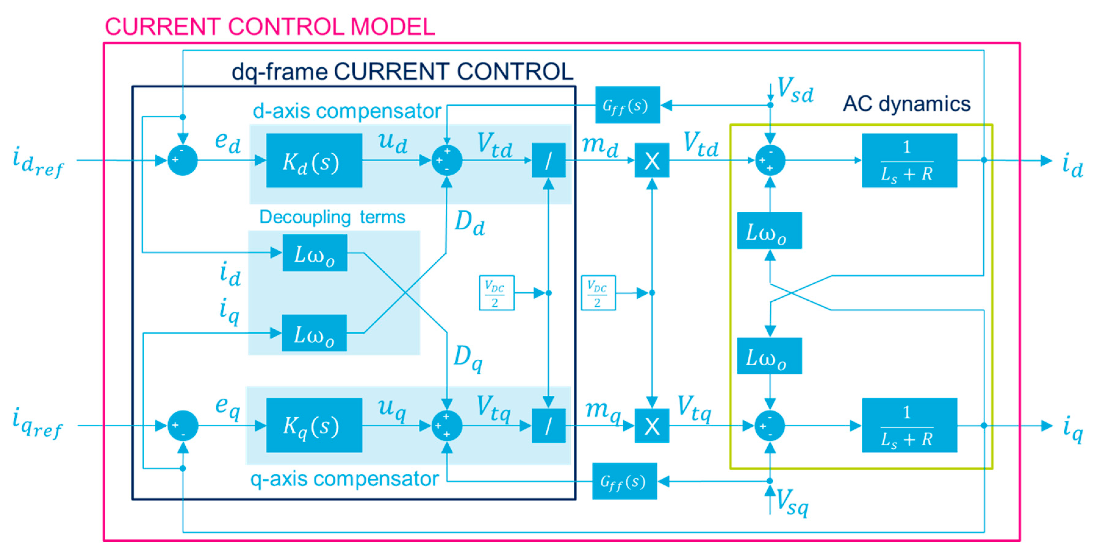
Finally, considering the general model, Equation (6), the command variables are obtained from the dq current control, Equation (7).
L d i d d t =   ω 0 L i q R i d + V t d V s d L d i q d t = ω 0 L i d R i q + V t q V s q
V t d = u d ω 0 L i q + V s d V t q = u q + ω 0 L i d + V s q
Simple and robust PI current regulators can be used to track references since the dq-axis signals in steady-state are constants (Equation (8)). The result is the controlled model given by Equations (9) and (10), as shown in Figure 4.
u d = ( k p + k i s ) ( i d r e f   i d f e e d ) u q = ( k p + k i s ) ( i q r e f   i q f e e d )
{ V t d = ( k p + k i s ) ( i d r e f   i d f e e d ) ω 0 L i q + V s d V t q = ( k p + k i s ) ( i q r e f   i q f e e d ) + ω 0 L i q + V s q
{ L d i d d t + R i d ω L i q = ( k p + k i s ) × ( i d * i d ) ω L i q L d i q d t + R i q + ω L i d = ( k p + k i s ) × ( i q * i q ) + ω L i q

2.2. Dual Active Bridge

The DAB is the DC/DC isolated bidirectional converter of the BBC (Figure 5). The DAB topology was chosen because of its high efficiency in a wide operating range [27]. It features a symmetrical structure, characterized by two full bridges connected via a high-frequency transformer which also provides galvanic isolation [28]. In Figure 6, a simplified equivalent circuit of the DAB converter is shown. The model of the transformer consists of two elements: the leakage inductor and an ideal transformer that models the voltage ratio. In Figure 7, a simplified circuit where the transformer has been represented on the secondary side to obtain a simple equivalent circuit is shown. The operating states of the converter switches are described in Equation (11).
v DAB 1 ( t ) = { + V 1 I T 5 , T 8   o n   &   T 6 , T 7   o f f 0 I I I I I T 5 , T 7   o n   &   T 6 , T 8   o f f T 5 , T 7   o f f   &   T 6 , T 8   o n V 1 I V T 6 , T 7   o n   &   T 5 , T 8   o f f v DAB 2 ( t ) = { + V 2 I T 9 , T 12   o n   &   T 10 , T 11   o f f 0 I I I I I T 9 , T 11   o n   &   T 10 , T 12   o f f T 9 , T 11   o f f   &   T 10 , T 12   o n V 2 I V T 10 , T 11   o n   &   T 9 , T 12   o f f
The H-Bridge on the left produces a square-wave voltage with a 50% of duty cycle on the primary side of the transformer. The right-side H-Bridge performs the AC to DC conversion and implements the current control loop used to shape the current charging profile of the battery. The leakage inductance, Llk, plays a key role in the performance of the power conversion. Among the various modulation strategies suggested in the literature, single phase-shift modulation was used to control the power exchange between the BBC and the main grid.
The phase-shift ( ϕ ) is positive when the power flows from the grid to the battery and negative when the it flows in the opposite direction. The relation between the phase-shift and the delivered power is given by Equation (12):
P = P DAB 1 = P DAB 2 = n V 1 V 2 ϕ ( π | ϕ | ) 2 π 2 f s L l k ,   π < ϕ < π
where −180° < ϕ < 180°, V1 and V2 are the input and output voltages of the DAB (Figure 8); n is the transformer turn ratio; fs is the switching frequency and Llk is the leakage inductance when considering a lossless DAB model.
P > 0 denotes a power transfer from DAB1 to DAB2 and P < 0 denotes a power transfer from DAB1 to DAB2. The power transfer as a function of the phase-shift is depicted in Figure 8. The related absolute presents two maxima at two different phase-shift angles. The maximum power occurs for ∂P/∂ϕ = 0 is:
P | P m a x | = n   V 1   V 2 8   f s   L l k ,   ϕ = ± π 2
Hence, for a specific active power P, the phase-shift ϕ that must be imposed between the input-output voltages is:
ϕ = π 2 [ 1 1 8 f s L | P | n V 1 V 2 ] s g n ( P )

2.3. High-Frequency Transformer

The high-frequency transformer is responsible for the power transfer and permits to obtain the galvanic isolation [29]. Different core geometries and materials are widespread and the selection of the most appropriate solution mainly depends on the specific application. It is well known that the use of high switching frequency reduces the core size for a given power, while using suitable ferrite materials effectively eliminates eddy currents losses.
The design method is based on the “core geometry method” [30,31].

2.4. Matlab—Simulink Implementation

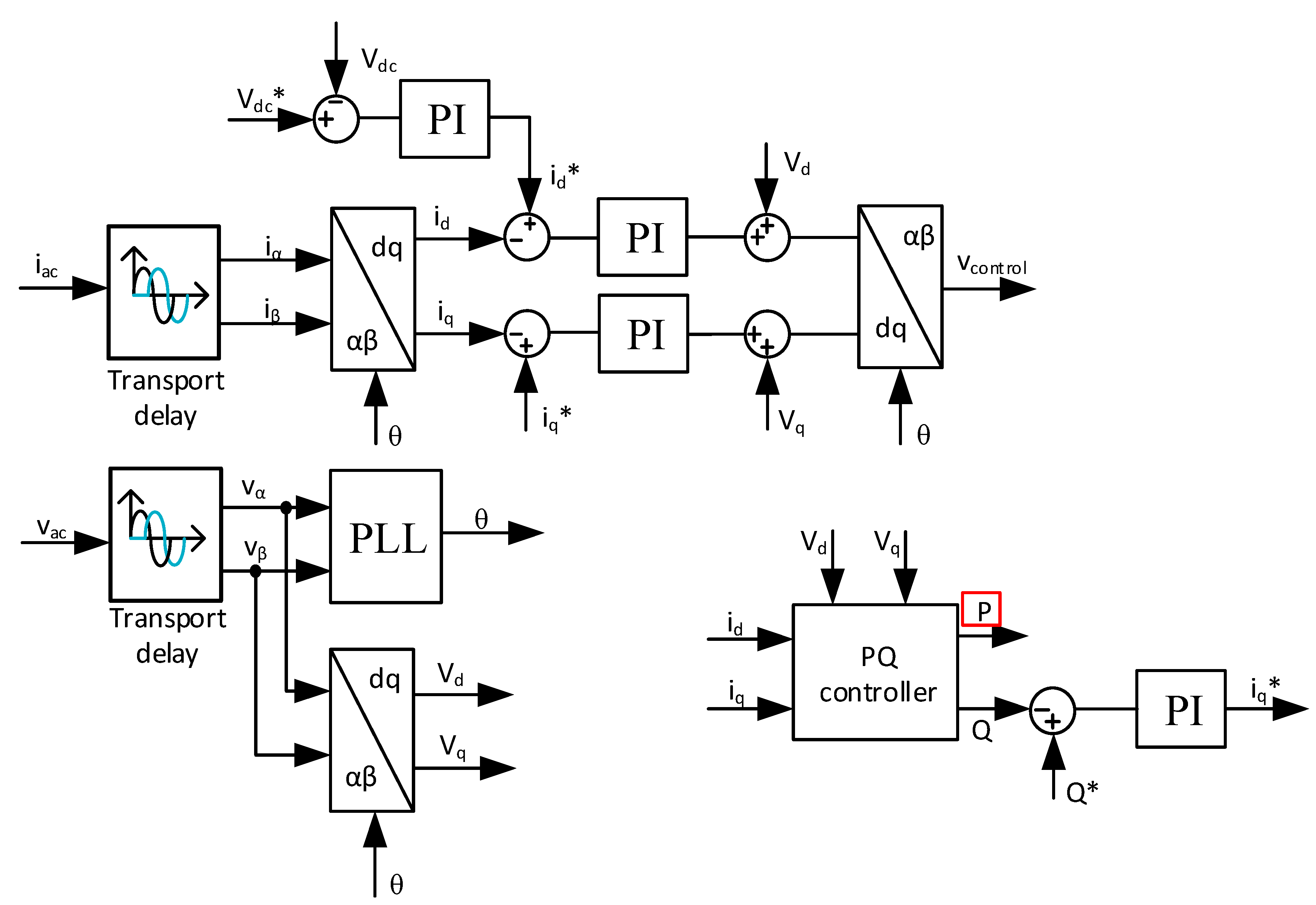
The model of the BBC and the model of its control were implemented in Matlab-Simulink to simulate the BBC behavior and to evaluate its performance considering different working conditions. The converter model included parasitic elements that affect each power conversion stage. The MOSFETs parameters were considered, as well as the dead-time set in the driving circuit. The closed-loop control block diagram for the AC/DC PFC converter is shown in Figure 9.
Using the Park’s transformation, the regulation was implemented using the id and iq current components to control, respectively, the active and reactive power. This control structure makes it possible to regulate both the DC voltage value and the PF. During G2V mode, the AFE with the PF correction works as an AC to DC converter, and charges the battery while maintaining constant the DC voltage and unitary the PF.
In V2G mode, the battery is discharged and the bridge acts in inverter mode (DC/AC). The control strategy consists of maintaining constant the voltage value on the bus-dc and managing the PF to compensate the amount of reactive power required by the grid. The control loop block diagram for the DAB is shown in Figure 10.

3. Simulation and Validation of the Model of Bidirectional SiC-Based Battery Chargers

A bipolar PWM was implemented with a switching frequency fs = 100 kHz. The switching frequency was selected as the best compromise between efficiency and high power density due to the reduction of the passives composing the AC grid filter and the DC bus link. The modulating signal was evaluated by the voltage grid angle implementing a grid synchronization algorithm setting a unity Power Factor (PF) in G2V or a stable grid synchronization in V2G. The gate signals used to control the SiC MOSFETs were set by the current control loop.
The technical specification of the filter parameters, DC bus link and grid operating conditions considered in the following analysis are listed in Table 1. The design specifications of the DAB of the proposed BBC are listed in Table 2.
For this bidirectional converter, the EE core geometry was chosen with N87 material grade. This choice was related to the high switching frequency (fs = 100 kHz) and high-power density of the transformer, whose characteristics are listed in Table 3. An increment in the switching frequency enabled a reduction of passive component size and weight but at the cost of greater switching power losses that, in turn, involve reduced efficiency. Therefore, the adopted frequency was the best compromise for such an application.
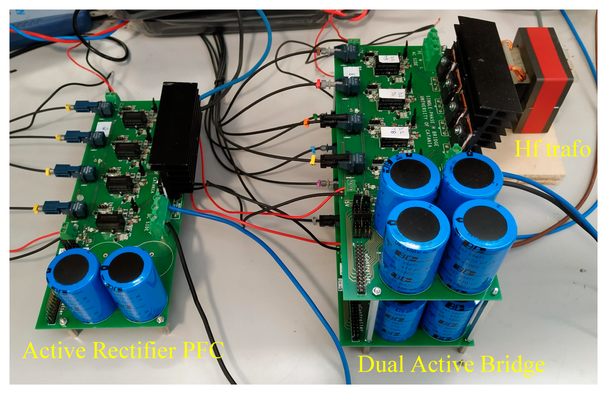
A prototype of the converter was designed and realized using components made by STMicroelectronics to validate the proposed tool by testing the performance and efficiency of the BBC designed using the proposed modelling approach. The power devices are SiC MOSFETs SCT50N120 (Table 4).
A mixed-signal MCUs STM32G474 was used to generate the phase-shift control signal and to manage the dead-time in each power converter leg exploiting the High-Resolution Timer (HRTIM) with 184 ps resolution. The digital control signals were conditioned and applied to the power switches using high-performance gate drivers STGAP2S, a galvanically isolated 4 A single gate drivers. This made it possible to achieve more compact and robust solutions for the entire experimental system.
The modular prototype and the test-bench are shown in Figure 11 and Figure 12.
The power required from the AFE acts on the phase-shift; by varying this reference, it is possible to reverse the power flow. Some simulated and measured waveforms obtained during the G2V mode are shown below. In Figure 13, the simulated first stage waveforms that are the grid voltage vac and current iac with unitary PF, and the ripple of the DC voltage are shown. The total harmonic distortion for the AC current was close to 7%, which is in accordance with the value measured (less than 10%) using the prototype.
The voltage and current on the primary side of the transformer are shown in Figure 14. The simulated waveforms were in good agreement with the measured ones. The main difference was the lack of oscillations in the simulated voltage. These oscillations were due to the coupling between the parasitic capacitance of the devices and the parasitic inductances in the power loop that were neglected in the model. The current waveform depends on the phase-shift between the two transformer-ends voltages. The secondary side quantities were pretty similar, as a turn ratio n equal to one was chosen. The leakage inductance, Llk, affected the power delivered in the DAB converter. Therefore, the voltage vL waveform was strictly related to the power direction. The DC output waveforms are shown in Figure 15, where the ripple of the voltage Vo and current Io are highlighted.
In V2G mode, the power flows from the battery to the grid to satisfy the power demand. In this case, the reference power is modified and acts on the phase-shift value as described above. The transition from G2V to V2G mode at the instant t* requires current inversion, as illustrated in Figure 16. In this case, the PF has been maintained, meaning that no reactive power was requested by the converter thanks to the proper control. The main simulation results are summarized in Table 5, while in Figure 17, the efficiency of the whole converter is shown.
Some other comparisons are reported in Figure 18, confirming the consistency of the proposed modelling approach.

4. Conclusions

This paper dealt with SiC MOSFET-based BBC with galvanic isolation. A promising topology was studied as the best choice in terms of efficiency, bidirectional power flow management and complexity. The development of an accurate tool accounting for the model of the converter in computer simulator and which was able to exploit FPGA was proposed. It has been shown that this is a suitable approach to design and test the performance of the complex control algorithm, both in G2V with PFC capability and V2G operation modes. The control strategy of the AC/DC converter is composed of a cascade control. One is able to regulate the power flow with the grid, while control of the DC/DC stage consists of the management of the battery charge/discharge. The design and the proposed approach were validated by comparing the simulation results with some experimental tests, confirming the consistency of the proposed method.

Author Contributions

Writing-Review & Editing: G.A., M.C., F.G., S.A.R., G.S. (Giuseppe Scarcella), G.S. (Giacomo Scelba). All authors have read and agreed to the published version of the manuscript.

Funding

This research received no external funding.

Conflicts of Interest

The authors declare no conflict of interest.

Nomenclature

AFEActive Front End
BBCBidirectional Battery Charger
CCMContinuous Conduction Mode
DABDual Active Bridge
EVElectric Vehicle
FPGAField Programmable Gate Array
GUIGraphical user interface
HRTIMHigh-Resolution Timer
PFPower Factor
PFCPower Factor Correction
PHVPlug-in Hybrid Vehicle
PLLPhase Locked Loop
SiCSilicon Carbide
V2GVehicle to Grid
ZVSZero Voltage Switching
CacLCL filter capacitor
Cdccapacitor between the AFE and the DAB
Cfoutput capacitor
LC, LSLCL filter inductors
Llktransformer leakage inductor
iα, iβtwo-phase stationary currents
id, iqtwo-phase rotating currents
iACline current drawn by the converter
iLlkcurrent flowing through the transformer leakage inductor
ioutoutput current
voutoutput voltage
v1DC/DC input voltage
v2DC/DC output voltage
v, vtwo-phase stationary converter voltages
vtd, vtqtwo-phase rotating converter voltages
v, vtwo-phase stationary AC main voltages
vsd, vsqtwo-phase rotating AC main voltages

References

  1. Shi, J.; Gao, Y.; Wang, W.; Yu, N.; Ioannou, P.A. Operating Electric Vehicle Fleet for Ride-Hailing Services with Reinforcement Learning. IEEE Trans. Intell. Transp. Syst. 2020, 21, 4822–4834. [Google Scholar] [CrossRef]
  2. Neffati, A.; Marzouki, A. Local energy management in hybrid electrical vehicle via Fuzzy rules system. AIMS Energy 2020, 8, 421–437. [Google Scholar] [CrossRef]
  3. Dominkovic, D.F.; Bačeković, I.; Pedersen, A.S.; Krajačić, G. The future of transportation in sustainable energy systems: Opportunities and barriers in a clean energy transition. Renew. Sustain. Energy Rev. 2018, 82, 1823–1838. [Google Scholar] [CrossRef]
  4. Franco, F.L.; Ricco, M.; Mandrioli, R.; Grandi, G. Electric Vehicle Aggregate Power Flow Prediction and Smart Charging System for Distributed Renewable Energy Self-Consumption Optimization. Energies 2020, 13, 5003. [Google Scholar] [CrossRef]
  5. Vadi, S.; Bayindir, R.; Colak, A.M.; Hossain, E. Vadi A Review on Communication Standards and Charging Topologies of V2G and V2H Operation Strategies. Energies 2019, 12, 3748. [Google Scholar] [CrossRef] [Green Version]
  6. Salvatti, G.A.; Carati, E.G.; Cardoso, R.; Da Costa, J.P.; Stein, C.M.D.O. Electric Vehicles Energy Management with V2G/G2V Multifactor Optimization of Smart Grids. Energies 2020, 13, 1191. [Google Scholar] [CrossRef] [Green Version]
  7. Juul, F.; Negrete-Pincetic, M.; Macdonald, J.; Callaway, D. Real-time scheduling of electric vehicles for ancillary services. In Proceedings of the 2015 IEEE Power & Energy Society General Meeting, Denver, CO, USA, 26–30 July 2015; pp. 1–5. [Google Scholar]
  8. Liu, C.; Chau, K.T.; Wu, D.; Gao, S. Opportunities and Challenges of Vehicle-to-Home, Vehicle-to-Vehicle, and Vehicle-to-Grid Technologies. Proc. IEEE 2013, 101, 2409–2427. [Google Scholar] [CrossRef] [Green Version]
  9. Kisacikoglu, M.C.; Ozpineci, B.; Tolbert, L.M. EV/PHEV Bidirectional Charger Assessment for V2G Reactive Power Operation. IEEE Trans. Power Electron. 2013, 28, 5717–5727. [Google Scholar] [CrossRef]
  10. Kisacikoglu, M.C.; Kesler, M.; Tolbert, L.M. Single-Phase On-Board Bidirectional PEV Charger for V2G Reactive Power Operation. IEEE Trans. Smart Grid 2015, 6, 767–775. [Google Scholar] [CrossRef]
  11. Xue, L.; Shen, Z.; Boroyevich, D.; Mattavelli, P.; Diaz, D. Dual Active Bridge-Based Battery Charger for Plug-in Hybrid Electric Vehicle with Charging Current Containing Low Frequency Ripple. IEEE Trans. Power Electron. 2015, 30, 7299–7307. [Google Scholar] [CrossRef] [Green Version]
  12. De Caro, S.; Testa, A.; Triolo, D.; Cacciato, M.; Consoli, A. Low input current ripple converters for fuel cell power units. In Proceedings of the 2005 European Conference on Power Electronics and Applications, Dresden, Germany, 11–14 September 2005. [Google Scholar]
  13. De Melo, H.N.; Trovao, J.P.F.; Pereirinha, P.G.; Jorge, H.M.; Antunes, C.H. A Controllable Bidirectional Battery Charger for Electric Vehicles with Vehicle-to-Grid Capability. IEEE Trans. Veh. Technol. 2017, 67, 114–123. [Google Scholar] [CrossRef]
  14. Restrepo, M.; Morris, J.; Kazerani, M.; Canizares, C. Modeling and Testing of a Bidirectional Smart Charger for Distribution System EV Integration. IEEE Trans. Smart Grid 2016, 9, 152–162. [Google Scholar] [CrossRef]
  15. Raciti, A.; Musumeci, S.; Chimento, F.; Privitera, G. A new thermal model for power MOSFET devices accounting for the behavior in unclamped inductive switching. Microelectron. Reliab. 2016, 58, 3–11. [Google Scholar] [CrossRef]
  16. Mohammed, S.S.; Devaraj, D. Simulation and analysis of stand-alone photovoltaic system with boost converter using MATLAB/Simulink. In Proceedings of the 2014 International Conference on Circuits, Power and Computing Technologies [ICCPCT-2014], Nagercoil, India, 20–21 March 2014; pp. 814–821. [Google Scholar]
  17. Doolla, S.; Bhat, S.S.; Bhatti, T.; Veerachary, M. A GUI based simulation of power electronic converters and reactive power compensators using MATLAB/SIMULINK. In Proceedings of the 2004 International Conference on Power System Technology, The Pan Pacific, Singapore, 21–24 November 2004. [Google Scholar]
  18. Aiello, G.; Cacciato, M.; Scarcella, G.; Scelba, G.; Gennaro, F.; Aiello, N. RealTime emulation of a three-phase vienna rectifier with unity power factor operations. In Proceedings of the 2018 ELEKTRO, Mikulov, Czech Republic, 21–23 May 2018. [Google Scholar]
  19. Aiello, G.; Scelba, G.; Scarcella, G.; Cacciato, M.; Tornello, L.; Palmieri, A.; Vanelli, E.; Pernaci, C.; Di Dio, R. Real-Time Emulation of Induction Machines for Hardware in the Loop Applications. In Proceedings of the 2018 International Symposium on Power Electronics, Electrical Drives, Automation and Motion (SPEEDAM), Amalfi, Italy, 20–22 June 2018. [Google Scholar]
  20. Aiello, G.; Tornello, L.D.; Scelba, G.; Scarcella, G.; Cacciato, M.; Palmieri, A.; Vanelli, E.; Pernaci, C.; Di Dio, R. FPGA-Based Design and Implementation of a Real Time Simulator of Switched Reluctance Motor Drives. In Proceedings of the 2019 21st European Conference on Power Electronics and Applications (EPE ’19 ECCE Europe), Genova, Italy, 2–5 September 2019. [Google Scholar]
  21. Scelba, G.; Scarcella, G.; Cacciato, M.; Aiello, G. Hardware in the loop for failure analysis in AC motor drives. In Proceedings of the 2016 ELEKTRO, Strbske Pleso, Slovakia, 16–18 May 2016. [Google Scholar]
  22. Acquaviva, A.; Thiringer, T. Energy efficiency of a SiC MOSFET propulsion inverter accounting for the MOSFET’s reverse conduction and the blanking time. In Proceedings of the 2017 19th European Conference on Power Electronics and Applications (EPE’17 ECCE Europe), Warsaw, Poland, 11–14 September 2017. [Google Scholar]
  23. Gritti, G.; Adragna, C.; Industrial & Power Conversion Division Application Laboratory—STMicroelectronics s.r.l.—via C. Olivetti 2—20864 Agrate Brianza (MB)—Italy. Analysis, design and performance evaluation of an LED driver with unity power factor and constant-current primary sensing regulation. AIMS Energy 2019, 7, 579–599. [Google Scholar] [CrossRef]
  24. Chimento, F.; Raciti, A.; Cannone, A.; Musumeci, S.; Gaito, A. Parallel connection of super-junction MOSFETs in a PFC application. In Proceedings of the 2009 IEEE Energy Conversion Congress and Exposition, San Jose, CA, USA, 20–24 September 2009; pp. 3776–3783. [Google Scholar]
  25. Yazdani, A.; Iravani, R. Voltage-Sourced Converters in Power Systems: Modeling, Control, and Applications; John Wiley & Sons: Hoboken, NJ, USA, 2010. [Google Scholar]
  26. Cacciato, M.; Scarcella, G.; Scelba, G.; Finocchiaro, L. Multi-reference frame based PLL for single phase systems in voltage distorted grids. In Proceedings of the 2014 16th European Conference on Power Electronics and Applications, EPE-ECCE Europe 2014, Lappeenranta, Finland, 26–28 August 2014. [Google Scholar]
  27. Jafari, M.; Malekjamshidi, Z.; Zhu, J.G. Analysis of operation modes and limitations of dual active bridge phase shift converter. In Proceedings of the 2015 IEEE 11th International Conference on Power Electronics and Drive Systems, Sydney, Australia, 9–12 June 2015. [Google Scholar]
  28. Cacciato, M.; Consoli, A. New regenerative active snubber circuit for ZVS phase shift Full Bridge converter. In Proceedings of the 2011 Twenty-Sixth Annual IEEE Applied Power Electronics Conference and Exposition (APEC), Fort Worth, TX, USA, 6–11 March 2011. [Google Scholar]
  29. Alves Ferreira Júnior, A.; Justino-Ribeiro, J.; Ney do Amaral Pereira, W. Evaluating Impedance Transformers with a VNA. Microwaves Rf 2009, 48, 64–71. Available online: https://www.researchgate.net/publication/243055235_Evaluating_Impedance_Transformers_With_a_VNA/references (accessed on 10 October 2020).
  30. Barrios, E.L.; Ursua, A.; Marroyo, L.; Sanchis, P. Analytical Design Methodology for Litz-Wired High-Frequency Power Transformers. IEEE Trans. Ind. Electron. 2015, 62, 2103–2113. [Google Scholar] [CrossRef]
  31. Hoang, K.D.; Wang, J. Design optimization of high frequency transformer for dual active bridge DC-DC converter. In Proceedings of the 2012 XXth International Conference on Electrical Machines, Marseille, France, 2–5 September 2012. [Google Scholar]
Figure 1. Overall picture of the evaluation tool.
Energies 13 06733 g001
Figure 2. Converter topology. The first stage is the Active Front-End Rectifier; the second stage is the Dual Active Bridge.
Energies 13 06733 g002
Figure 3. AC Stage—Implementation of the Active Rectifier in Simscape electrical Simulink.
Energies 13 06733 g003
Figure 4. Current control diagram. i d q r e f current references, e d q   current errors, v d q   compensator terms, D d q   decoupling terms, V t d q   control voltages, m d q   modulation index.
Energies 13 06733 g004
Figure 5. DC/DC stage Dual Active Bridge.
Energies 13 06733 g005
Figure 6. DAB equivalent circuit W/ transformer.
Energies 13 06733 g006
Figure 7. DAB equivalent circuit W/O transformer.
Energies 13 06733 g007
Figure 8. Power transfer vs. Phase-shift.
Energies 13 06733 g008
Figure 9. AFE PFC closed-loop control block diagram.
Energies 13 06733 g009
Figure 10. Phase-shift control loop block diagram.
Energies 13 06733 g010
Figure 11. A prototype of the bidirectional battery charger.
Energies 13 06733 g011
Figure 12. Prototype test-bench.
Energies 13 06733 g012
Figure 13. Voltage and current of the AC grid and ripple on the DC side.
Energies 13 06733 g013
Figure 14. Voltage on both sides of the transformer, voltage and current of the inductance. (a) Simulated waveforms; (b) measured waveforms.
Energies 13 06733 g014aEnergies 13 06733 g014b
Figure 15. Ripple on the DC output Voltage and Current.
Energies 13 06733 g015
Figure 16. AC voltage and current from G2V to V2G mode.
Energies 13 06733 g016
Figure 17. Efficiency vs. (a) power output and vs. (b) phase shift.
Energies 13 06733 g017
Figure 18. DAB: voltage and current waveforms. (a) Simulated (b) Measured.
Energies 13 06733 g018
Table 1. Technical specification of the AFE parameters.
ParameterValue
RMS voltage grid230 V
Grid frequency fe 50 Hz
Ls1.5 μH
Filter parameter Cac10 μF
Filter parameter Lc325 μH
Cdc400 μF
Switching frequency fs100 kHz
Table 2. DAB design specifications.
ParameterValue
Nominal input Voltage Vdc400 V
Nominal output voltage Vo400 V
Minimal output voltage Vo,min150 V
Output Power 5 kW
Duty Cycle0.5
Switching frequency 100 kHz
Table 3. Technical specification of the transformer parameters.
ParameterValue
Nominal Input Voltage400 V
Maximum Input Voltage480 V
Minimum Input Voltage360 V
Input current22 A
Nominal output voltage400 V
Output Current17.5 A
Regulation α0.15%
Max operating flux density Bm0.16 T
Maximum temperature rise Tr70 °C
Table 4. Power device description: SiC MOSFET SCT50N120.
SymbolParameterValue
VDSMaximum drain-source voltage1200 V
IdDrain current (continuous) at TC = 25 °C65 A
RDS (on)Static drain-source on-resistance at 150 °C59 mΩ
Tj Max Operating junction temperature in HiP247™200 °C
Table 5. V2G operation—Simulation quantities and results.
ParameterValue
RMS grid voltage Vs230 V
RMS grid current Is22.6 A
Average Bus DC Voltage Vdc403 V
Average output voltage Vo397 V
Average output current Io12.4 A
Input Apparent Power S5200 VA
Input Active Power Pac5200 W
Bus DC Power Pdc5030 W
Output Power Po4910 W
Power Factor0.999
Displacement Power Factor 1
Total Harmonic Distortion7%
AFE efficiency η = PDC/Pac96.7%
DAB efficiency η = Po/PDC97.6%
Power Efficiency ηp = Po/Pac94.42%
Conversion Factor ηc = Po/S94.26%
Publisher’s Note: MDPI stays neutral with regard to jurisdictional claims in published maps and institutional affiliations.

