1. Introduction
The global warming crisis is becoming one of the most dangerous threats that we will have to face worldwide in this century. The ever-accelerating growth rate of the world economy and industrial production has led to steadily increased greenhouse gas (GHG) production. Since the year 1997, when the Kyoto Protocol was signed, which is the first international treaty for limiting and reducing GHG emissions, the signed state parties have started their journey for sustainable development and a cleaner environment. The latest legal extension of the Kyoto Protocol framework is the Paris Agreement from 2015. Within this agreement, the long-term temperature goal to keep the average world temperature increase at least below 2 °C in comparison with preindustrial levels (approx. 1880) was negotiated and set [
1].
The European Union (EU), since the Kyoto Protocol was signed, has established itself as an international leader in the energy transition from fossil fuels towards clean energy, and this approach is reflected in its ambitious energy and climate policy [
2]. The current EU general energy policy framework from 2019 sets out to achieve the following goals by 2030: (1) reduction of at least 40% in GHG compared to 1990 levels (currently, there is an ongoing EU discussion about the increase up to 55–60%), (2) increase to 32% of the share of renewable energies in the final energy consumption, (3) improvement of 32.5% in energy efficiency, and (4) the interconnection of at least 15% of the EU’s electricity transmission systems [
3]. The strict climate–energy policy set in this way will continue in the future and should lead to a carbon-free economy in 2050. To successfully achieve the main goal state of charge (SoC) in 2050, the GHG emissions and energy consumption must also be significantly reduced from the transport sector, which accounts for almost a quarter of the total environmentally hazardous emissions in Europe and is responsible for 33% of the final energy consumption (353 Mtoe) [
4]. Within the sector, road transport is responsible for more than 70% of all GHG emissions from transport in the EU and is individually responsible for pollution in densely populated areas [
5].
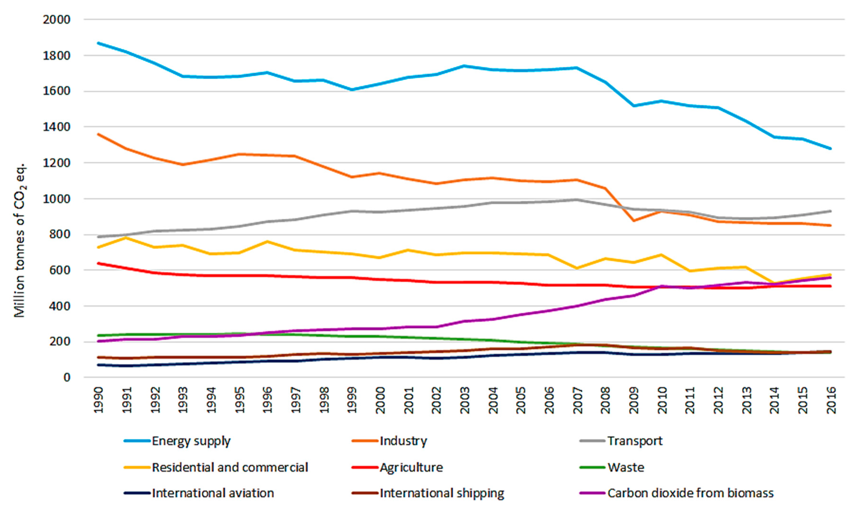
Figure 1 shows that the production of GHG emissions from the transport sector does not show the same decline trend over the years as the emissions produced from other sectors in the EU28. For the first time, the production of emissions from transport began to decline in 2007. At the end of 2018, however, GHG emissions produced by transportation again reached the level of 2007, almost 1100 Mt CO
2e.q. In 1990, the production of emissions was 862 Mt CO
2e.q. [
6]. The EU answers to this unsatisfactory development and the challenge of reducing transport emissions with urgent and irreversible transitions to zero-emission mobility. By the year 2050, GHG emissions from transport (including aviation but excluding international maritime) will need to be reduced by at least 60% compared to 1990 [
5]. The European Commission has set an average car fleet CO
2 target 95g CO
2/km for all new cars to accelerate the reduction of emissions from the road transport sector. This limit is expected to be further rapidly tightened; by the year 2030, a stringent standard at 70 g CO
2/km is planned [
7]. Emission standards like that will no longer be able to meet by conventional combustion cars, so car manufacturers will have to raise their low/zero emissions vehicle shares significantly [
8].
According to the International Energy Agency, at the end of 2019, over 1.5 million electric vehicles (EVs) (including battery electric vehicles (BEVs) and plug-in hybrid electric vehicles (PHEVs)) were registered in the EU [
9]. The total number of registered EVs in the EU is expected to accelerate its growth due to the falling prices of battery technology (battery cost breakdown) and government financial subsidies and support [
10]. According to estimates of the cumulative number of EVs based on optimal development, EU countries will have more than 10 million electric vehicles by 2030 [
11].
In the next few years, the rapidly expanding EV market will start producing a large amount of waste, especially battery waste, which is not easily recyclable [
12]. This fact is also confirmed by the analysis that the Global Composite Annual Growth Rate of Lithium-Ion Batteries (batteries most commonly used as energy sources in EV) will grow by 36% between 2015 and 2020 [
13].
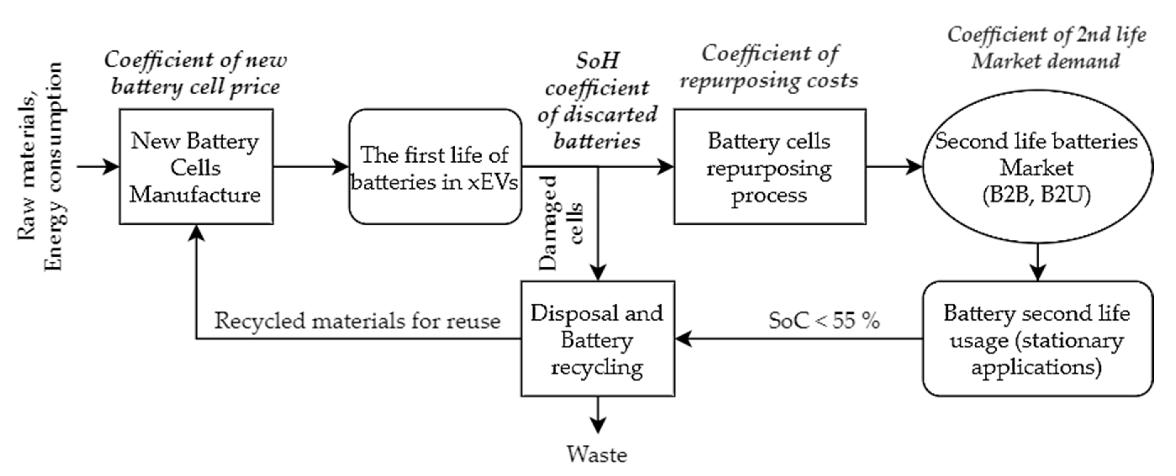
Batteries are usually discarded from electric vehicles when they reach a level of about 80% of their original capacity after their first life cycle in EVs, which is usually about 8 to 10 years [
14,
15]. However, these discarded batteries are, due to their technical and safety parameters, still suitable for use in stationary applications with less demanding load profiles [
16]. Hence, instead of collecting and recycling used batteries, batteries are collected and sent through the repurposing process. Within this process, the state of health (SoH) of discarded battery cells is checked, and batteries are being prepared for their second lives [
17]. According to a study “New life for used EV batteries as stationary storage” by Bloomberg New Energy Finance, the global cumulative discarded capacity could reach 26 GWh by the year 2025.
Through this repurposing process, the total battery lifespan is prolonged, the current amount of waste is minimized, and the idea of the circular EU economy is fulfilled. Further usage of discarded battery cells will also bring significant financial savings, savings in GHG emissions, and a reduction of primary energy consumption that would otherwise arise from the production process of new battery cells [
18]. The idea of a secondary use of discarded batteries could also help accelerate the development of the already accessible high-capacity battery storage, the development of which is still hampered by the high cost of battery technology [
14]. The current price of new battery Li-ion technologies ranges from 200 to 300 USD/kWh and, according to initial studies and analyses, the price of discarded battery cells should not exceed 35% of the price of new battery cells of the same technology [
15].
Second-life batteries (SLBs) could be used in a wide variety range of stationary applications for the transmission and distribution grid but, also, for commercial purposes such as load shifting, peak shaving, black start, backup, and grid deferral [
19]. Due to the specific technical parameters of batteries, such as providing high performance (high output power) with a short response and activation time, these discarded batteries could find applications—primarily, in stationary applications supporting grid stability control and the integration of increasing numbers of grid-scale decentralized energy sources (DERs) [
20]—as their output power is variable and uncontrollable over time and whose installation is necessary for the fulfillment of defined climate and energy targets EU [
15].
The fast development of distributed generation brings new challenges, especially in the field of voltage and frequency regulation of the power grid [
21]. Battery systems are becoming crucial providers of fast frequency control services, also known as fast frequency containment process (FCP) [
22]. FCP is an ancillary service provided to the transmission system operator (TSO) with the shortest reaction time, in the order of tens of seconds, and the time until full activation of the provided power backup does not exceed 30 s. That is the reason why this service is dedicated to cover fast and small changes in transmitted power in the power grid. In Germany, there is currently installed more than 400 MW of output power and a capacity of about 550 MWh of large-scale storage systems (LSS), which operate mainly in the frequency containment reserve (FCR) market [
23].
The technical condition after the decommissioning of traction batteries from EVs and their possibility for usage in LSS for network control and support was already analyzed in several research papers and studies [
24]. Jeremy S. et al. from the National Renewable Energy Laboratory, within their study, focused on SLB degradation, and their SoH status concluded that, with a proper energy management system (EMS) and optimal operating strategy, repurposed automotive batteries can last 10 years or more in stationary applications [
25]. The method for optimal EMS design and the optimal sizing of the battery energy system storage (BESS) energy capacity using SLBs for enhancing renewable energy grid integration was studied and proposed in [
26]. However, in reference [
27], four different application scenarios on a real stationary SLB storage were simulated and tested (support EV charges, area frequency regulation, self-consumption, and grid investment deferral), and each of these applications differed dramatically in the length of its secondary life. In the frequency area regulation scenario, the secondary lifespan was only 4.7 years until the BESS was no longer able to meet the technical requirements for FCP providers, and these investments will be economically unprofitable. According to this study and others, the lifespan of BESS is most affected by the depth of discharge (DoD) and the average state of charge (SoC) [
28,
29,
30]. Additionally, in [
21], the operation of SLBs in BESS are simulated in three network support model cases—namely, peak shaving, voltage control in power systems, and ancillary services. During the study, the authors found a positive impact on the operation of the energy system at all voltage levels in the use of BESS (no economic evaluation included in this study).
With this identified knowledge in mind, the focus of this paper was to propose a complex mathematical model based on real historical electricity frequency data obtained from the TSO to investigate the technical suitability and economic efficiency of SLB usage in BESS. The simulation model was developed and tested in MATLAB (R2020b, MathWorks, Natick, MA, USA). In order to achieve optimal and relevant results, according to the analyzed critical technical lifespan parameters, the emphasis was placed on the optimal BESS capacity sizing and the design of an optimal strategy for the SoC and DoD battery management within the operation. A modeled SLB BESS was used for the provision of FCP services using the harmonized European Balancing Guidelines, and it was verified in the environment of the Czech regulating energy (RE) and ancillary services market. For the correct economic evaluation of the BESS operation during the whole secondary battery lifetime, several different scenarios were created following the impact of the newly emerging interconnected European market with RE [
31].
3. Frequency Regulation in European Standards
The frequency regulation process—often called simply balancing—includes all actions and processes through which TSOs, on an ongoing basis, ensure the maintenance of system frequency within a predefined stability range around the nominal value of the system frequency [
32]. The nominal frequency value (
fN) in the synchronously working area within the Union for the Coordination of Transmission of Electricity (UCTE) is 50 Hz. The difference between the actual system frequency
f(
t) and nominal frequency value is called the frequency deviation, ∆
f, as shown in Equation (1). Frequency deviation occurs in the transmission grid when the total electricity generation does not equal to total electricity consumption within the controlled region of the TSO. By the frequency deviation definition, it is apparent that the deviation can have both negative and positive values. Negative values correspond to the demand being greater than the electricity generation, and positive values are linked with the situation when the generation exceeds demand.
Currently, TSOs within Europe use slightly different processes and products to ensure the balanced state of the grid due to disparate historical developments and balancing philosophies. In order to achieve the highest future security and reliability of interconnected transmission network operations, an internal market for sharing the balancing energy and power reserves within the synchronously operating area was created on the basis of a cooperation agreement signed by participants of the European Network of Transmission System Operators for Electricity (ENTSO-E) [
29].
Figure 3 illustrates the proposed harmonized sequence of regulation processes to achieve cooperation and a successful integration of the common European balance energy market within the load frequency control (LFC) area or block.
The harmonized frequency recovery process consists of four consecutive provided power reserves. For each type of balancing reserve in the process, different technical requirements are set in the Network Code of ENTSO-E. Balancing service providers (BSPs) offer bids on the balancing market to TSOs of their available power reserve or energy capacity within the services listed below. The price of accepted bids is determined on the basis of the marginal price of all BSP bids and total procured volume for each trading interval of the market.
frequency containment reserve (FCR)
automatic frequency restoration reserve (aFRR)
manual frequency restoration reserve (mFRR)
replacement reserve (RR)
After the occurrence of an imbalance, the FCP service power reserves are activated first to contain the system frequency. The FCP service is the one with the shortest activation time, and it also provides the lowest amount of active power reserves per unit. These are the main reasons why this service is suitable for providers offering a performance within the limited storage capacities of BESS. In this study, we designed and verified the operation of a stand-alone BESS, which does not have a backup resource unit. Therefore, we focused only on providing reserves within the FCR.
3.1. Frequency Containment Process
Within the frequency regulation process, the total provided unit power reserve (
PN) is activated automatically by a primary frequency control device. The controller secures the real-time system deviation measurement and a constant ratio between the system frequency disturbance and activated output power. The expression for the regulation control mechanism of the required activated reserve (
PR) is given as follows:
The generator drop
SG is a ratio (without dimension), and it represents the ability to regulate the required activated reserve continuously. The ratio is generally expressed as a percentage:
The amount of automatically activated power reserve is linearly proportional to a system frequency deviation. As mentioned earlier, the frequency system variety could be both positive and negative, so FCP is a symmetric service, and both positive and negative FCR are required within it. The minimum volume of provided FCR by one unit is 1 MW, and the maximum is 25 MW, with the step of 1 MW for market bidding. The maximum FCR capacity is activated in the case of a system frequency deviation ±200 mHz. According to the ENTSO-E Guideline on Electricity Transmission System Operation (GETSO) [
34], each BSP connected to the TSO shall ensure that the FCR offered fulfills the operation requirements and meets the technical properties. The reaction time of full FCR activation has to comply with the following requirements:
At least 50 % of the FCR power reserve must be delivered no later than 15 s after the request.
The full value of the FCR power reserve must be delivered no later than 30 s after the request.
If the frequency deviation in the power grid is higher than 200 mHz, the increase in activated FCR power must be at least linear in the range of 15 to 30 s.
By the FCR report part of the TenneT Network Code [
35], the state when the frequency deviation in the power network is in the range [−50 mHz, +50 mHz] is considered as a normal operating state of the system. During this time, the availability of each unit providing the FCR to the grid must be 100%. If the grid frequency exceeds the value of ±50 mHz from
fN, a warning state of the frequency recovery process is recognized whenever at least one of the following situations occurs:
exceeds ±50 mHz for a longer time than 15 min
exceeds ±100 mHz for a longer time than 5 min
whenever exceeds the maximum allowed system frequency deviation of ±200 mHz
If the frequency recovery process enters the warning regime, all FCR units must be able to deliver their maximum contracted power (PN) for 30 min. In the remaining parts of this study, we call this condition the 30-min criterion.
3.2. SoC Management Strategy
Due to the physical nature of secondary battery cells and their limited storage capacity, it is crucial to provide optimal an BESS SoC management strategy and to keep the charge level within the optimal operating range to meet the 30-min criterion at any time without interruption of the FCR supply. In Czech TSO’s Network Code, there is no section devoted to providing FCR through stand-alone energy storage. For the purposes of this study and realistic assumptions for the harmonization of the requirements and rules for the provision of the FCP service, the rules set by the transmission system operators in Germany will be used. Allowed operation strategies in Germany to maintain the SoC within the optimal charged range have been already analyzed by several studies aimed at providing balancing reserves and ancillary services through LSS [
36,
37]. These strategies aimed to ensure that the SoC level will not exceed the operating range are called degrees of freedom (DoFs). Electricity obtained through all DoF strategies is free of charge.
3.2.1. Over-Fulfillment (OF)
The current unit output power set by the FCP regulation controller could be optionally increased by up to 20% at any time. Over-fulfillment is the main DoF to maintain the SoC, as it can provide effective additional BESS charging and discharging during providing balancing service.
3.2.2. Dead Band (DB)
The range of ±10 mHz around the nominal frequency is considered as the dead band (DB), within which the provision of FCR is not mandatory. DB management of the SoC is allowed only when the correction power is not in the direction of the current frequency deviation and does not cause an additional imbalance in the system.
3.2.3. Gradient Controller Increase (GC)
The controller gradient represents the minimum required activated power ramp slope, which is given by the requirement of a fully activated power reserve within 30 s. As BESS are able to change their output power very quickly, in the order of hundreds of milliseconds, the power change gradient over time can be changed and used to control the SoC.
3.2.4. Market-Based Energy Trade
The three DoF strategies mentioned in the previous subsections are excellent support tools for maintaining the SoC level in the permitted operation area, but in cases of high network frequency deviations, their potential is insufficient. To ensure the SoC limit remains sufficient for FCR provision, the energy needed to charge and discharge the battery is traded on the intraday energy market (IEM). There are two possible ways to use this strategy:
3.3. FCR Power to Frequency Characteristic
In the following
Figure 4, we depict a graphic representation of all possible operating characteristics during providing a reserve for the FCP service via the BESS. The basic Δ
P-Δ
f (commonly known as power to frequency ratio) output characteristic (black dashed curve) is given by Equation (2), and its curve shape confirms that the activated power reserve is linearly proportional to a system frequency deviation.
3.4. Frequency Containment Reserves Market
Within this study to evaluate the technical possibility and economic efficiency of SLB usage in BESS for participating in the FCR Market, we made the assumption that the Czech TSO is already an active participant of the ENTSO-E Project FCR Cooperation. Currently, Czech Republic TSO is only in the role of an observer, but we are expected to become a full member in the upcoming years. This precondition allows us in the economic model to calculate with the historical prices of settlement FCR bids. FCR Cooperation aims to integrate the balancing market to foster effective competition, increase liquidity, and support the speed of deployment of renewable energy sources. The Austrian, Belgian, Dutch, French, German, and Swiss TSOs currently procure their FCR in a common market, which means that they have the same conditions, auction period, and same symmetric product [
38].
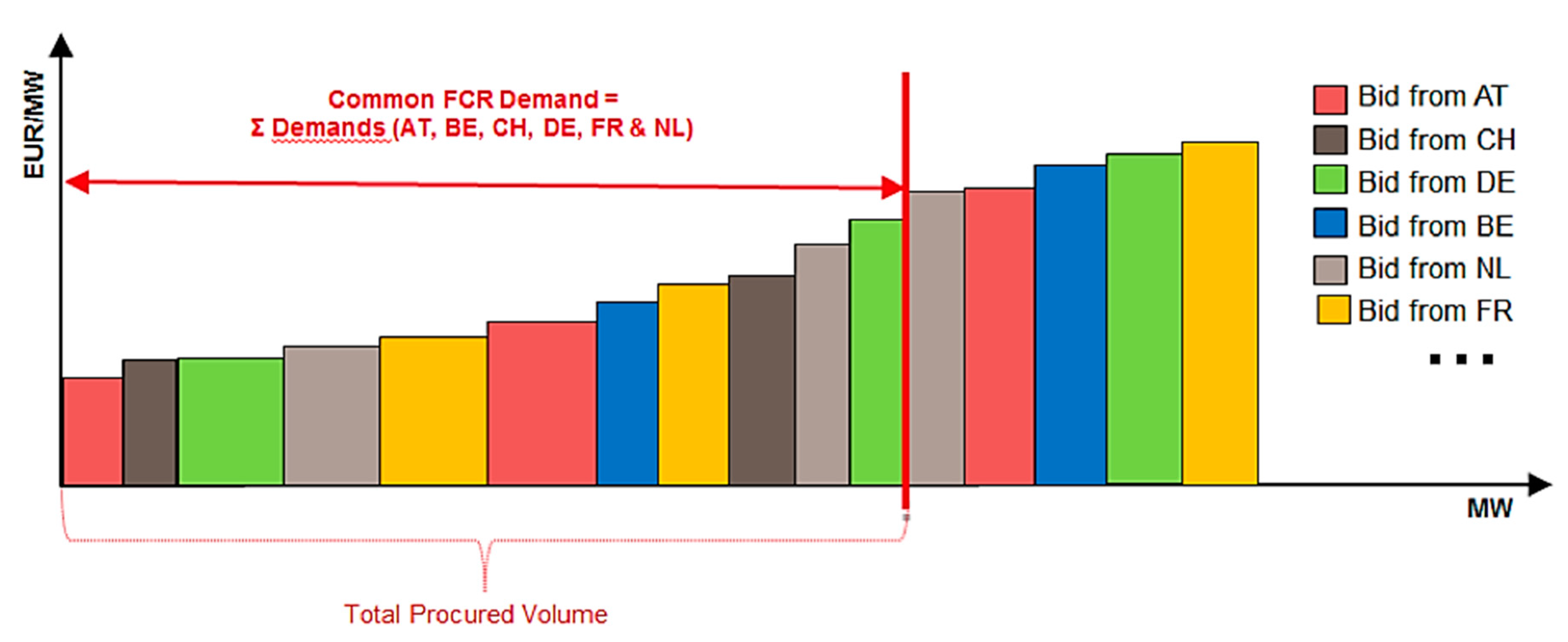
The FCR cooperation secures power reserves through the common FCR market with daily D-1 (day-ahead) tender type and standard 4-h FCR products. A D-1 tender type means that every FCR provider posts their bids to the market platform the day before the delivery at 8:00 h. The FCR settlement price is determined for every tender period (4 h) and is calculated by merit order pricing methodology, which is represented in
Figure 5.
3.5. FCR Provision Requirements Summarized
In
Section 3 of this study, we analyzed the ancillary services, its market, and defined all necessary conditions and requirements that must be met when offering the FCP regulation power reserves capacity. In
Table 1 below, we summarize the most important technical or operational parameters that will be further used in BESS modeling and the optimal SoC control strategy design.
4. Mathematical Operation BESS Model
In the following section, the proposed methodology of BESS modeling in MATLAB is presented. The simulated BESS model is assumed to be based on second-life traction Li-ion batteries, so we adapted the technical operation parameters of the model to this fact. With this in mind, we wanted to achieve safety FCP provision and the longest possible lifespan.
4.1. Frequency Data Analysis
The grid frequency data from 2015 to 2018 were analyzed for the purpose of the main inputs of the proposed model. The historical frequency datasets were taken from the annual evaluation of the transmission system operation on the Czech TSO ČEPS website (only the Czech version, ČEPS, a.s., Prague, Czech Republic). During the analysis process, some inconsistent frequency samples
fi,Error were identified. Values such as 0 Hz or no data measured were replaced by the calculation method shown in (4).
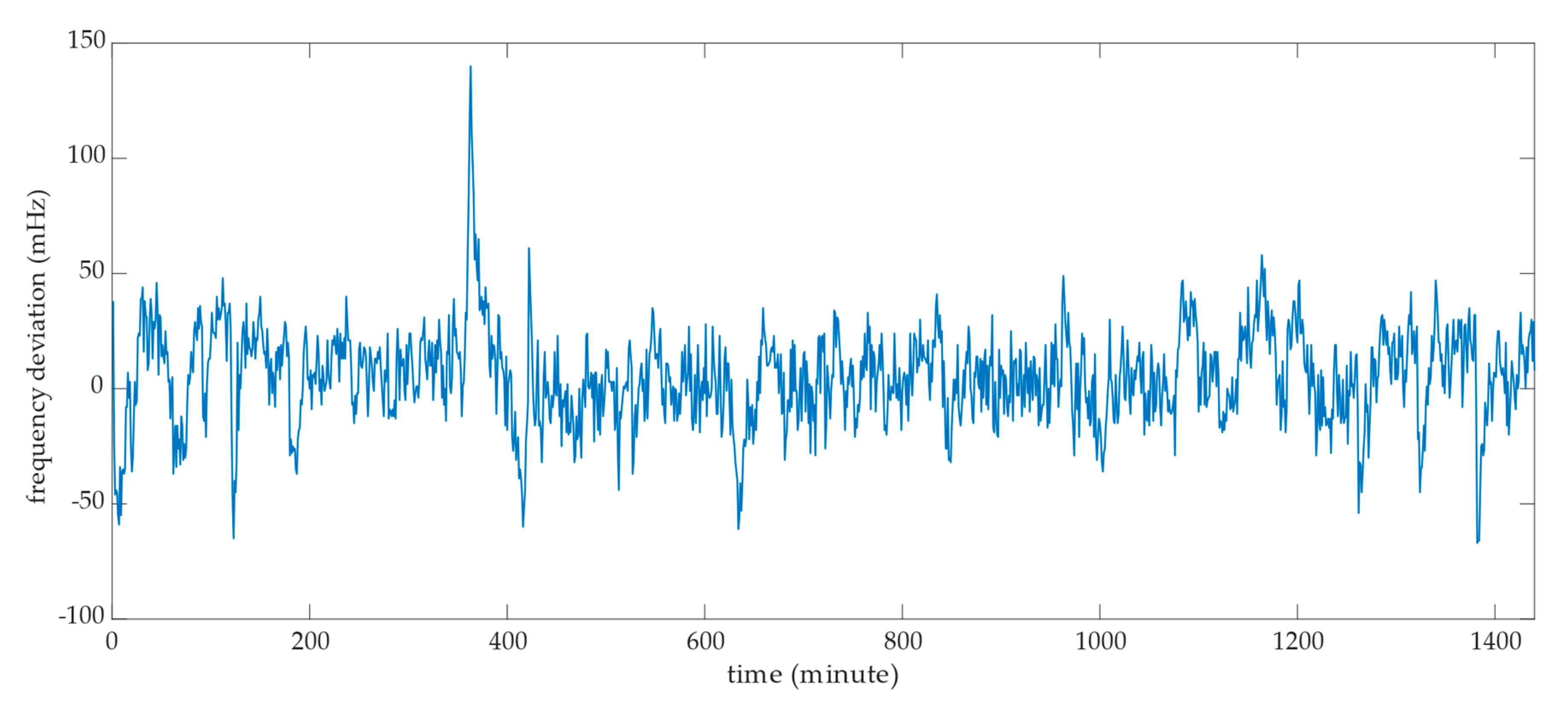
Within this statistical analysis, we examined whether the BESS during the FCP provision will more often inject or extract the electrical energy from the power grid. In the following
Figure 6, we present a graphical representation of the mathematical and statistical functions of the analyzed set of frequency deviation samples in the Czech transmission network in 2018.
The probability density function is skewed right, which points to the fact that the frequency deviation is, more often, positive. This state is the same for all datasets from the analyzed years. According to the power to frequency ratio (Δ
P-Δ
f) characteristics (
Figure 4), we made a presumption that the BESS will be extracting energy more often from the grid, which, in battery logic, means more frequent charging. In
Table 2, we present numerical values from the performed frequency data analysis, which will be crucial in the design of the optimal BESS operating strategy.
4.2. Optimal Operation Strategy
The design of an optimal battery system management strategy is key to obtaining the system’s lifespan under real operating conditions and to perform the final technical-economic evaluation of BESS operation. We based the design of the optimal strategy on the technical parameters of Li-ion battery cells, the requirements for FCR service providers (see
Table 1. Summary of the central requirements and conditions for the provision of the frequency containment reserve (FCR) service within the synchronously operating EU system), and the results of the statistical analysis of historical frequency data.
As we examine the possibility of using discarded battery cells in this paper, lithium nickel manganese cobalt (NMC) battery cell technology will be used in the proposed and simulated LSS. NMC battery technology was chosen as it had a more than 65% electric vehicle (EV) market share in 2019 [
39].
4.2.1. NMC Battery Cell Parameters
NMC battery cells have a longer cycle life, more stable operation, and higher energy density than other battery technologies (nickel cobalt aluminum (NCA), lithium iron phosphate (LFP), and lithium cobalt oxide (LCO)) used on the EV market nowadays. NMC batteries also do not suffer from such high self-discharge during the nonoperation or low output power time, which is advantageous for small-frequency deviations in the grid. In
Table 3 below, we present the basic technical parameters of the chosen battery cell chemistry. The table data were analyzed on the website of Battery University and from the article [
40].
From the table above, the critical parameters for designing the operational strategy are the allowed voltage operation range and both C-rate values. The C rate is a dimensionless quantity that determines the permitted battery power and can be expressed as follows:
The C rate gives us the ratio between the maximum continuous output power and the battery’s total installed capacity. In the discharge C-rate row in
Table 3, we state two values; the higher one (2C) can be used only for a short period of the time. Otherwise, the battery degradation process will be accelerated. We decided not to use the possible 2C discharge rate during our modeling during the grid’s normal operation state. The only case when we decided to allow the BESS to give 2C discharge output power was when the TSO declared a state of emergency.
Therefore, in our annual simulated model, we further operated with three possible cases of setting the maximum limit of the BESS output power to reach the maximum lifespan during the operation.
The FCR power-to-frequency basic principle (
Figure 5), Equation (6) will limit the BESS model’s output power in the case of positive frequency deviations in the grid. On the other hand, we have to consider Equations (7) and (8) in times of negative frequency deviations.
The voltage operating range is shown in
Figure 7 and is given by charging and discharging the NMC battery cell curve. From the courses of these characteristics, we determined the assumption that we will consider the course of the charging and discharging curves in the range from 10% SoC to 90% SoC as linear. Regarding the study of the effects of cycling on lithium-ion battery hysteresis and overvoltage [
41], we decided not to operate the BESS outside the linear range. Operating the battery in these areas means overvoltage or undervoltage of the battery cell. These operating conditions place additive stress on the battery cell chemical structure and a consequent rapid decline in life. The SoC and stored energy limitation in the proposed BESS FCR model are determined as follows:
The average operating SoC and SoC of the battery inactivity affect the resulting battery life. According to Battery University and the data in
Table 3, the average lifespan of NMC batteries is 2500 equivalent full cycles with an estimated 80% DoD cycles calculated for the optimal operating conditions, which are the following: operation temperature around 25 °C and medium SoC cycling [
42]. In response to this knowledge, and the fact that we are integrating discarded batteries that are more prone to degradation, the optimal strategy design will focus on maintaining the battery charge level between 40% and 60% SoC to prolong the battery lifetime.
Outside of the set optimal SoC BESS level, the correction DoF strategies will be used, either individually or mixed according to the current BESS SoC level, the present value of the system’s frequency deviation, and the grid’s operation state.
4.2.2. Permitted SoC Range
In the previous section, we analyzed and set the optimal operating parameters of the performance and charge level BESS to reach the optimal battery cell’s technical lifespan. This section will design the battery system’s optimum size based on the desired parameters and FCP provisions of the services.
When designing the optimal size of the BESS, we considered meeting the 30-min criteria and the availability of 100% of the time during the normal state of the network operation. We also considered that the power reserve in the FCP service is provided in both directions. The BESS must be ready to supply energy within the 30-min criterion in the up and down directions. We also had to consider the limitation of 10% and 90% SoC given by the discharge and charging curve of the battery NMC cell.
The results of these considerations are represented in the graph in
Figure 8. The permitted continuous working area is determined by the ratio between the installed BESS capacity and the maximum possible reserve within the FCP service. The ratio is calculated for the NMC battery cell technology, and we consider here the discharging and charging C rate equal to 1.
According to Equations (11) and (12), the optimal interval of the SoC (40% and 60%) of the working area was determined based on the analyzed optimal technical operating parameters. Following these values, we further simulate the BESS operations with a capacity-to-power ratio at least higher than 1.6 to meet the defined optimal work area.
4.3. Annual Operation MATLAB Model Design
In this section, the simulated annual BESS operation during the FCP provision is designed and tested. During the simulation, the necessary correction strategies were activated based on the current frequency deviation in the grid and the SoC level of the storage system. The size of the battery storage’s output power and the composition changes over time may consist of the following possible composition power performance. All degrees of freedom analyzed in earlier sections of this paper are summarized together in the BESS SoC correction degrees of freedom output power P
DOFs.
The BESS output power consists of the main power within the delivery of the FCR power reserve (P
FCP), power of the correction strategy within the dead band (P
DB), and power within over-fulfillment (P
OF). Power obtained with the gradient controller increase strategy (P
GC) is given by the time of the preset ramp (
), which is smaller than 30 s. The amount of output power given by trading on the intraday energy market (P
ET) was determined by whether the 30-min criterion was held. In the case that 30 min criterion is held, the BESS has 2 h to restore the optimal SoC level, so the minimum P
ET is given as half of the power of FCR provided (in our case 5 MW). The resulting output power was determined by the overall energy supply efficiency of the battery system. We determined to use for academic purposes a 93% total discharge efficiency and 95% total charge efficiency regarding a discussion with colleagues from the Battery Technology Department and the results in a study by S. Madani [
40]. In these percentages, we included a coulombic efficiency of 99% of the NMC battery cells as well.
The size of each power outputs within the individual SoC level correction strategies and their activations were decided on the basis of the actual frequency of the grid and BESS parameters. The following
Table 4 represents the combinations of allowed power operating states that may occur during the simulation and the possibilities of what SoC correction strategies are available at these times. The information of the current frequency deviation and the prediction of its near-development is essential, as none of the permitted correction strategies must go against the purpose of maintaining the system stability.
Within the proposed annual simulation, we used and calculated the following variables and BESS operation technical parameters. The value of each of them was determined for every timestamp of the analyzed historical frequency data.
The state of charge of the BESS (SoC
t) is the function of actual output BESS power, previous SoC level, time of the power activation, and installed BESS capacity. In the annual model, we use a timestamp equal to 1 min, as given by the historical measured frequency datasets. The current SoC level is equivalent to the following relation:
The BESS stored energy level (E
BESS,t) is calculated simultaneously through slightly different relations:
SDNMC,day in the equation above represents the self-discharge mechanism of the NMC battery cells, and the variable
TSday is determined as the number of samples during the day. According to the time samples of the network frequency, we consider its value of 1440 per day. In our simulation of NMC cell degradation, we determined to calculate with 0.15% self-discharging per 24 h due to the acknowledgements and methods from the study of the self-discharge principles of NMC Li-ion cells by Thomas Deutschen et al. [
43].
The curve represents the amount of energy stored in the BESS during the annual modeled operation. We calculated the whole year’s energy flow through the battery storage system. This information is crucial in calculating the battery’s estimated degradation time using the equivalent full cycle (EFC) methodology. In our model, we worked according to the SoC set working limits, with a maximum allowed DoD of 80%.
We determined the number of performed EFCs during the annual simulation through the volume of energy corresponding to the full discharge cycle with an 80% depth.
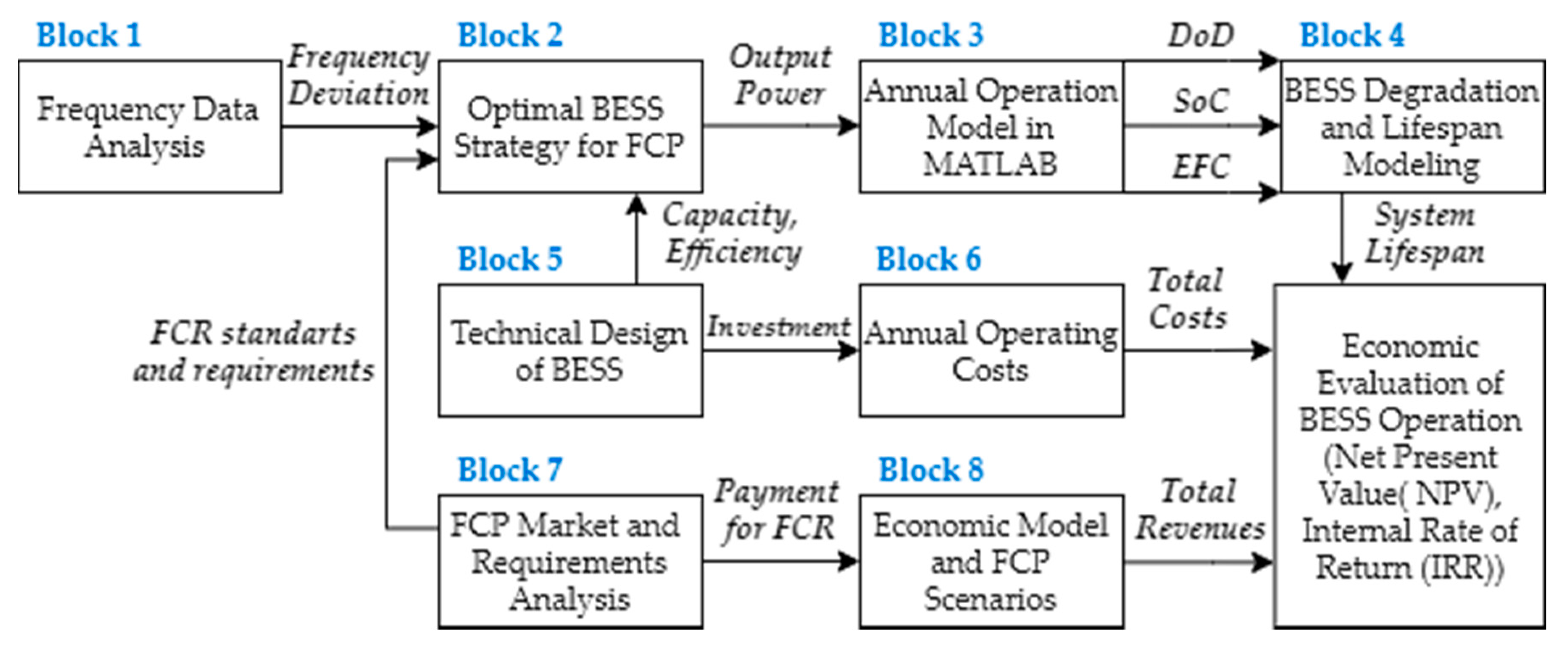
To describe and illustrate the proposed model and the annual simulation principle, a flow chart was created, which is shown in the
Figure 9.
4.4. Technical BESS Design
The proper technical design of the main battery storage components and the final selected BESS capacity is an integral part of our complex model, since it directly affects the possible range of power reserve provided within the FCP service.
For this simulation, and the optimal choice between the revenues from the provision of the network support service and the amount of investment in the BESS, we decided to provide 5-MW FCR power reserve to the TSO.
Regarding the set values of BESS operating parameters in the previous sections, the optimal operating band of 10% and 90% SoC and the resulting minimum ratio of 1.6 between the installed capacity and maximum power are specified in
Section 4.2.2. Permitted SoC Range, we should install storage equipment with an installed capacity of at least 8 MWh.
However, this paper’s main idea was to use discarded batteries from electric cars during their second lives. These batteries have a lower initial capacity, greater propensity to accelerate degradation, and sufficient capacity reserve in the FCP service provision. Therefore, our proposed storage has an initial installed capacity of 10 MWh.
The proposed battery energy system storage consists of five separate container storages, and all of them are connected to the distribution system (DS) on the voltage level of 22 kV. These containers can be operated separately in the case of necessity or accident, so each has its technical components needed to connect to the network. This fact will provide us with a greater possibility of variability in the use of storage in the future if we are not successful in the tender in the market to provide FCR power backups. Should this case occur, we can use the BESS, for example, for energy arbitrage, trading in electricity, or charging it in times of negative prices in the electricity market. This technical design and separation of the total installed capacity will result in a reduction of the economic risk of the BESS operation during its estimated lifetime.
Table 5 summarizes all technical and operational parameters of the proposed BESS, which will be applied as basic inputs for the simulation. A more detailed overview of the components used will be given in
Section 5.3.1. Initial investment, where their prices calculate the calculation of capital expenditures to acquire the proposed BESS.
4.5. Annual Operation Model Results
This section applied the corrected historical data of frequency deviations on the BESS programmed model, already having selected the technical parameters, as listed in
Table 5.
To illustrate and prove the proposed model’s correct functionality, we examined the limit case that may occur during operation in the power system. The characteristics and waveforms of the individual BESS output operating parameters (SoC, power, and P-f) will be examined for the day of the maximum positive frequency deviation in the transmission system in 2018.
The day of the maximum positive frequency deviation represents when the BESS must extract lots of energy from the grid, so the presumption is that the SoC of the BESS could rise above the upper allowed SoC operation limit. The following
Figure 10,
Figure 11,
Figure 12,
Figure 13,
Figure 14 and
Figure 15 show the effects of the proposed optimal SoC control strategies in contrast to the BESS operating without any control strategies allowed when the output power of the storage is linearly equal to the current Δ
f within this day.
Verification of the proposed control strategy’s proper design and functionality for managing the optimal charge level of the large-capacity storage in operation was successful. The impact of using allowed strategies of degrees of freedom is more than evident in the BESS power characteristic shown in
Figure 13. This characteristic represents times during the day of maximum positive frequency deviations when the BESS mostly increases its output power to discharge itself additively and to remain with the SoC level in the permitted working range.
The
Table 6 summarizes the primary and crucial outputs from the annual simulations, working with frequency datasets from 2015 to 2018. Some of them are being used for the final lifespan estimation, and some of them are needed to calculate the economy of the BESS investment.
The number of times the BESS charge level falls outside the allowable operating range indicates that even the complex proposed SoC battery management strategy cannot fully and timely correct the increase or decrease in battery charge.
During the annual simulated BESS operations, this condition also occurred on other occasions than only during the warning state of the frequency recovery process within the transmission system according to the conditions analyzed in
Section 3.1. Frequency Containment Process.
When the BESS reached the lower SoC limit, although not a single warning state condition was met, it occurred on 7.2.2018 and was represented in the following
Figure 16 and
Figure 17.
From the course of the frequency curve during the example of days in
Figure 16, it may not be evident at first glance why the lower limit of the SoC was violated during the provision of the FCP service. We examined the values of frequency deviations in the network within the interval when the SoC drop occurred in more detail. The value of the network deviation lasted for almost five h between 0 mHz and −50 mHz. Although, the essence of declaring an alert condition in the network was not fulfilled within this time interval, the state of long-lasting low negative-frequency deviation did not allow the battery to use correction strategies according to the rules given in
Table 4, and the energy storage system slowly discharged despite the relatively low output power.
The correction of this limit situation of the BESS operation through the purchase of additional corrective energy on the intraday market is described in the diagrams in
Figure 17. The SoC level course shows how its level decreased almost continually within the analyzed five h.
Avoiding limit situations such as this could be achieved by combining the real-time market trading of electricity and the simultaneous provision of FCP without interruption. This advanced combined strategy would be reflected in the BESS output power by the power offset in the direction of the physical flow of energy currently traded on the market.
However, the question is whether this strategy will be allowed by the national regulator and TSO. There would be a shift in the sense of power output against the direction of the required application of the FCR power reserve. This situation could be counterproductive and cause a worsening of the balance situation in the network.
4.6. Second Life Lifespan Estimation
Determining the correct lifespan based on the simulation outputs is a critical part of this paper. The investment’s economic efficiency is directly affected by the asset’s final technical lifetime under review.
Many studies have already dealt with the degradation principle of battery cells during operation. We based the lifespan estimation at the battery cells aging principles in storage on the knowledge from studies [
42,
44,
45]. A look at the aging of the battery cell, which most authors agreed on, is the possibility of dividing the aging of the battery into two independent principles according to the following equation:
Degradation of the battery due to time (“calendar”) is entirely independent of the number of cycles performed and the depth of discharging or charging the battery. The rate of decrease in battery capacity is affected by the calendar storage conditions: SoC (%), temperature (°C), time (years), and cathode chemistry of the cells used as described by Equation (22).
Rodrigo Martins et al., in their study, focused on the LSS for industrial applications; they linearized the course of calendar degradation over 10 years [
46]. Their linearization for new NMC battery cells is shown in the following equation:
We modified this linearized model within our model based on using discarded batteries, which already have a different degradation process, possible different SoC states, and operating temperatures.
Unlike the calendar capacity fade, the decrease in the battery cell’s capacity in operation is strongly dependent on the number of performed work cycles and their average depth of discharge. The operating parameters of the BESS affecting the rate of degradation of the batteries in operation are shown as a function in Equation (24).
Concerning the function above, we decided to use the EFC discharge capacity retention methodology for NMC battery cells described by Yuliya Preger et al. [
44] to determine the cyclic degradation’s final contribution to the overall capacity fade.
Within our model, we introduced the assumption of maintaining a constant operating temperature of the BESS at 25 °C. This assumption can be considered valid, as the containers are equipped with a cooling system, air conditioning, and the C-rate coefficient value is set so that there is no additive warming of the battery.
We identified the average BESS charged level within the annual operation via simulated output SoC values and its probability distribution function shown in the following statistical analysis in
Figure 18. We compared the most different years, 2018 and 2016, regarding the distribution of frequency deviations in the power grid. For the lifespan estimation, we calculated with an annual average SoC equal to 55%.
We determined the DoD parameters to calculate the battery degradation based on Equation (25), where N = individual BESS FCR activations during the year, ΔP = power curve during one activation, t1 = start time of a given FCR activation request, and t2 = FCR activation request end time.
The average discharge depth of the simulated battery storage ranged from 17% to 20% during the examined frequency historical datasets from the available years. We decided to calculate within the degradation model with an annual DoDavg = 18%.
Figure 19 shows methodologies for determining the resulting BESS lifetime. According to the analyzed simulation outputs, the simulated repository was most often operated at the SoC level of 55%, considered the middle level. On the contrary, the average depth of the performed cycles did not exceed 20%. We consider this value to be a low cycling window. The EFC input value was selected as 460 cycles per year based on the data in
Table 6.
With an average of 460 EFC cycles/year, assuming an average operating temperature of 25 °C, an average operation SoC level 55%, and a DoD < 20%, the BESS lifetime is estimated at 8.7 years in terms of cyclic capacity degradation. The contribution of calendar degradation is, according to the assumed constant operating parameters for 10 years for the second life of the battery, according to
Figure 19b, a 2.35% decrease of the initial residual capacity after decommissioning from EVs (80% of the original capacity). Our model estimates an effect of calendar degradation of 2% because of our time step <10 years, which, according to the capacity retention methodology, corresponds to 320 EFC. The lifetime of the modeled high-capacity secondary battery storage is determined as follows:
To calculate the investment’s economic efficiency, the life of battery cells in the repository of eight years is considered in the following sections.
We can consider this secondary battery cell lifespan under the established assumption that, in the future, there will be no massive changes in the behavior of the power system or a massive change in the distribution and frequency of frequency deviations in the grid.
6. Results and Discussion
The
Table 10 summarizes the results for all evaluated combinations of the three main and three FCP scenarios. Based on these results, we can conclude that all possible combinations have a positive internal rate of return. This means that all are able to cover the initial investment and generate an additional return on the investment. With 10% of the required return on investment (discount rate), three out of nine scenarios showed negative results and would be rejected by potential investors, and the remaining six generated additional revenue above the required discount rate.
However, the main problem in terms of setting a discount rate to 10% is the amount of risk connected with the bidding strategy and short-term contracts. Some investors may ask for significantly higher values, especially at the first phases of their entry to the new harmonized short-term ancillary market. Therefore, there is an urgent need for the further discussion of involved stakeholders how to reasonably minimize investors’ risk with the help of legal framework so that there is no need for direct financial support caused by higher requested discount rates.
The usage of second-life batteries also significantly reduces the amount of initial investment costs compared to entirely new battery storage systems, and if we compare the technical parameters, storage systems based on discarded batteries deliver the complete same services comparable to new battery systems. Even from the point of view of operational safety, discarded battery systems do not pose any increased risk. After passing their initial measurement and inspection, they meet all safety requirements for the operation of battery systems.
The obtained results for the Czech case are fully transferable to all EU countries with interconnected electricity markets and ancillary services. The economic effectiveness of second-life batteries will be almost the same across all these countries. The reasons supporting this statement are:
- (1)
The market for second-life batteries will be very likely a joined one within the whole EU, and therefore, the price for 1 MWh of a discarded battery will vary only to a minimal extent. However, there is also an open question as to what extent the manufacturers of batteries (or big car-producing companies) will control the market using specific and very likely closed softwares that allow cars to properly charge and control their batteries.
- (2)
The prices for the provision of ancillary services will be similar across all interconnected countries in the EU, copying the price development of electricity (power) prices. The reason for such predicted price unification lies in the new harmonized regulations for the ancillary services market, such as the European Balancing Guidelines (EBGL), System Operation Guideline SOGL, and Clean Energy Package CEB.
- (3)
The price of electricity, as one of the main operation expenses, is almost always similar thanks to interconnected and harmonized power markets in the EU. The only time when the electricity price may differ is the case of insufficient cross-border transmission capacities, which leads to a break-up of the one unified price area.
The only main factor that can significantly a change in the final economic efficiency is direct and indirect financial support of the BESS operation. This can then indirectly affect the whole market for cross-border shared ancillary services. For this reason, there should be an effort to avoid significantly different support across individual EU countries.
To find the limit values of the economic model’s main input parameters to maintain the BESS investment’s economic rentability, a set of two-parameter sensitivity analyses of the NPV are proposed. Assuming the uncertain development of the available power capacity and the number of future balancing service providers in the emerging interconnected market for ancillary network services, the following parameter combinations were examined: the amount of payment for the provided FCR reserve, average annual provided FCR, and number of won hour tenders.
To examine the effects of the changes in the values of these parameters on the resulting NPV, the other input parameters of the model were set to the basic values according to
Table 9, the main realistic scenario.
In the
Table 11, the green line indicates the limit combinations of the examined parameters for maintaining the economically profitable operation of the BESS in the provision of FCP service. These combinations are valid and relevant for the economic evaluation when considering the predicted FCP 2 price development scenario, the values of which are given in
Appendix A. The coloring of
Table 11 and
Table 12 highlights the BESS project’s economic rentability regarding the input parameters combination. The green color represents the state when BESS’s operation is economically efficient and the red color represents the state when BESS operation is non-profitable.
The second two-parameter sensitivity analysis performed aimed to determine the amount of FCR payment with a variable volume of won hourly annual tenders is presented in
Table 12. The provided power reserve is 5 MW and is constant throughout the economic evaluation.
Through the performed sensitivity analyses, it can be stated that maintaining the economy of the BESS operation with the required return of 10% is maintained even with relatively significant decreases in the examined key operating economic parameters. The predictability of future values of the examined parameters during real operations is very limited, and it is necessary to take into account very variable differences in prices for the provided power reserves for FCP during the individual tender periods (days to hours).
The BESS operators can defend themselves against sudden price changes in the FCP market by changing the bidding strategy or by allocating the installed capacity for different services on separate units in the event of a decrease in the amount of reserves. All these facts support the future motivation of investors to acquire a BESS, leading to their widespread increase in popularity.
Crucial to the future emergence and development of the market for discarded battery cells will be the position taken by electric vehicle manufacturers in this resulting battery value chain. The question is whether vehicle manufacturers will be interested in these discarded capacities or will the discarded capacities be collected by newly established companies that will directly specialize in the secondary use of batteries and the repurposing process. However, car manufactures are increasingly aware of the growing value of discarded batteries, which is influenced by the expected high participation of storage technologies in the electricity market.
There is, therefore, a high presumption that individual vehicle manufacturers will have a policy for the disposal of discarded batteries and will, therefore, use or redistribute them themselves after decommissioning from electric vehicles. A possible variant also remains that the battery modules will be owned by the car manufacturer throughout the life of the customer’s electric vehicles, which will replace the full capacity for a lower fee at the end of life.
7. Conclusions
Battery cells discarded from the electromobility sector still offer sufficient technical and safety parameters for further usage. They can find their utilization in a wide range of applications, especially in stationary energy storage, where the ratio of power to weight is not a crucial parameter, as it is in the case of EVs. This fulfils the idea of a circular EU economy to save the primary energy resources needed in production and to achieve a careful use of natural resources and valuable raw materials.
Such utilization also contributes to the further development of renewable energy generation from intermittent sources, such as solar and wind. However, a further increase of such renewable sources will also create an increased demand for fast and reliable balancing services that are currently provided primarily by fossil fuel-based power plants and that can be effectively substituted by sufficient and economically available energy storage.
Battery systems can also significantly help with charging infrastructure development for the expected rapid increase in electromobility, especially in densely populated agglomerations. In these agglomerations, currently used power line transmission capacities may reach limit values. Thus, the BESS working in parallel with charging stations can relieve the high required power for charging purposes, delay the necessary investment in strengthening the line’s transmission capacity, and minimize the risk of overload due to the impact of fast charging.
From an economic point of view, battery systems based on discarded batteries appear to be viable for the provision of FCP without direct financial support, even in scenarios reflecting relatively unfavorable price developments.
The proposed and presented procedure for the optimization and evaluation of battery systems can also be fully used (when resetting several input parameters) for the assessment of other types of stationary systems, such as charging hubs for e-mobility. Discarded batteries could thus significantly support the development of the charging infrastructure, with all the resulting benefits.
The proposed general methodology was verified on the Czech Republic case; however, the obtained results are fully transferable to all EU countries, thanks to interconnected electrical grids and, also, harmonized markets for power and ancillary services. The proposed methodology approach can also be easily adjusted to a vast number of similar tasks that evaluate the technical and economic feasibility of large battery systems. To conclude, the discarded batteries from the dynamically developing electromobility sector have high potential for their second lives. There are possible applications that can fully utilize discarded batteries with promising financial results. These utilizations also indirectly contribute to achieving the EU’s climate goals towards carbon neutrality in 2050 and energy independence.


