Article

Research on Additional Control Technology Based on Energy Storage System for Improving Power Transfer Capacity of Multi-Terminal AC/DC System with Low Cost

1
State Grid Jiangsu Electric Power Co., Ltd., Nanjing 210024, China
2
Research Institute of State Grid Jiangsu Electric Power Co., Ltd., Nanjing 211103, China
3
Institute of Electrical Engineering, Chinese Academy of Sciences, Beijing 100190, China
4
The School of Electronic, Electrical and Communication Engineering (EECE), University of Chinese Academy of Sciences, Beijing 100049, China
*
Author to whom correspondence should be addressed.
Energies 2020, 13(2), 495; https://doi.org/10.3390/en13020495
Submission received: 4 December 2019 / Revised: 10 January 2020 / Accepted: 14 January 2020 / Published: 19 January 2020
(This article belongs to the Section A1: Smart Grids and Microgrids)

Abstract

:
The multi-terminal AC/DC system will become one of the important forms of the future power grid. The negative impedance characteristic caused by the constant power load in the DC network will reduce the power transfer capacity between the terminals, especially when a grid fault occurs in AC system at any terminal. Energy storage has played an important role in improving the stability of AC and DC systems. This paper proposes an additional control method based on an energy storage system to improve system power transfer capacity with low cost. The state space model of two-terminal AC/DC system is established, and the feedback laws for additional control are further designed by Lyapunov theory. Furthermore, the additional control strategies based on the energy storage system is built, without changing the existing control system of each control object. Finally, the corresponding system simulation model is established by Matlab/Simulink for analysis and verification. The research results show that the proposed additional control method is effective. The power transfer limitation can be overcome by only adding small damping energy with the stable DC voltages under large disturbances, and the power transfer capacity between the terminals can be significantly improved with low control cost.

Graphical Abstract

1. Introduction

Due to the rapid development and wide application of the renewable energy, new material and, power electronic technology, and the growing requirement for high power supply quality, reliability, and efficiency, the current AC power distribution system is facing great challenges like diversified requests for power customers, modularized connection of the distributed renewable energy, and complex control of power flow, etc. On the one hand, the form and the number of electrical devices in the power distribution system have changed: a large amount of DC facilities like electrical vehicles, energy storage equipment have been put into use [1]. On the other hand, if the distributed generation (DG) of a photovoltaic system and fuel cell connect directly to the DC grid, the conversion links can be reduced, so the efficiency of the system can be improved [2]. Thus, the growing need for DC devices makes the development of DC power distribution technology an inevitable tendency in the future. Currently, the AC devices are still the main load in the power system. With the connection of the DC equipment, the AC and DC loads will be coexistant for a long period. Therefore, the AC/DC hybrid system is going to play an important role in the future [3,4,5].
In America, Virginia Tech builds a hybrid power distribution system based on the connection of layered AC and DC subgrid [6]. North Carolina State University proposes a future renewable electric energy delivery and management (FREEDM) system [7]. They build a 400 V DC system and a 120 V AC system which are connected to the power grid via intelligent energy management (IEM). The microgrid system of Osaka University [8] and the universal and flexible power management (UNIFLEX) in Europe [9] both design their own AC/DC hybrid system. The AC/DC hybrid system has different structures like point-to-point interconnection or looped circle, hand-to-hand connection, parallel supply pattern, and its derived forms and so on. Among them, the multi-terminal interconnection configuration has fundamentally changed the original structure of the AC power distribution system as well as the connectivity of its branches. The system thus has flexible controllability, diversified topology structure and good network connectivity. This brings remarkable improvement to the system in terms of functional flexibility and power supply reliability. Apart from this, multiple power electronic converters in the DC system, especially VSCs which control the power flow between the DC and AC system, can transfer the power flow from weak AC system to another safe area through DC system by coordinate control, in order to compensate the reactive power and balance the system load. Through multi-terminal coordinate control, system has wider range of power sharing ability and power supply capability. This means that, with the help of the controllable DG, flexible topology of multi-terminal DC interconnection and accurate power flow control, the AC/DC hybrid system can provide plenty of functions like emergency control, power oscillation damping and dynamic mutual voltage support, etc., which can reduce the impact and influence caused by disturbances, therefore, improving the global stability of the whole system. Currently, the demonstration project of a multi-terminal DC system in Baolong, Shenzhen [10] and hybrid AC/DC microgrid with multi-bus structure in Shangyu, Zhejiang [11] are under construction.
It is worth noting that when an AC side fault happens in one of the terminals in the system, the upstream circuit breakers/switches trip then the local AC load will lose its power supply. If important or sensitive load exists which needs uninterrupted power supply, then the VSC needs to change to the AC V/f control mode quickly after the breakdown (for example, within one cycle time) in order to guarantee the continuous and reliable power supply for the load on the AC side. At this point, the control strategy of this VSC comparing to the whole system is equivalent to the P&Q control (which means the output power of this VSC changes automatically with its AC side load). Normally, the power transfer ability of this VSC is considered to be able to reach its rated capacity. However, on one hand, in a multi-terminal AC/DC hybrid system, when the DC/DC converter uses closed-loop control to regulate the load voltage, it presents the dynamic characteristic of constant power load (CPL) [12]. Both the DC/DC converter and the DC/AC VSC under the P&Q control mode appear the negative impedance feature, which will further aggravate voltage changes under fluctuation of the DC voltage, and even destabilize the system in some serious cases [13,14]. This will weaken the stability of the DC system and the whole system. On the other hand, the low damping resonance link which consists of the equivalent impedance of the DC line and the filter of each VSC, will interact with the output impedance of the VSCs [15]. Its resonance characteristic will induce unstable high frequency oscillation, therefore reducing the power adjustment capability of the AC/DC system. This means that the actual power transfer capacity of the VSC is limited, and it is lower or significantly less than its rated capacity and the operating domain of the multi-terminal AC/DC hybrid system shrinks correspondingly, which will bring down the economics of the system [16].
Tools for the stability analysis of a DC system with CPLs, such as block diagonalized quadratic Lyapunov function, Takagi-Sugeno (TS) multi-modelling, and Brayton-Moser’s mixed potential function, are proposed [17], on the basis of these, other relevant scholars come up with an additional damping control method to solve the problem of improving the stability margin of DC microgrid and multi-terminal DC power distribution system, including constructing the control function based on linearization via state feedback (LSF) (one part represents the compensation for performing linearization on the non-linear system, and another part is used for the configuration of poles) to cope with the instability effect of CPL, in order to enhance the stability of the DC voltage [18]. Aiming at the DC voltage oscillation caused by poor interaction between the power electronic device and the DC network in the multi-terminal DC power distribution system, an active damping control strategy based on the inner current loop is proposed which can improve the ability of mutual power compensation among several power electronic equipment and significantly expand the stability domain [19].
At present stage, research is mainly focusing on adding additional regulators inside the control loop [18,19], or local control strategy of the DC-DC converter and VSC. Some studies using a fractional order proportional integral derivative (PID) control strategy, which can provide an excellent start-up response besides desired dynamic response, or other methods as like fuzzy-PID are proposed [20,21,22]. A rare study has been done considering the global information and coordinated control from the system level based on the local control of each device, using the energy storage device in the DC network to improve the stability and the power transfer boundary of the system, without changing the existing structure of the local controller and its control strategy of each device. On the purpose of solving the above problem, this paper proposes an additional control technology of the energy storage system (ESS) to overcome the negative impedance feature and the limit of VSC power transfer under DC network resonance, and improve the stability of the overall multi-terminal AC/DC system by generating only a small amount of additional power for ESS.
The structure of the paper is described below: Section 2 demonstrates the equivalent circuit and the mathematical model of a multi-terminal AC/DC system. Section 3 gives an analysis of power transfer capacity of this multi-terminal AC/DC system. Section 4 proposes an additional control strategy based on the ESS and its design of the feedback laws. Section 5 presents the corresponding simulation and verification, while Section 6 is the conclusion based on the above theory and simulation results.

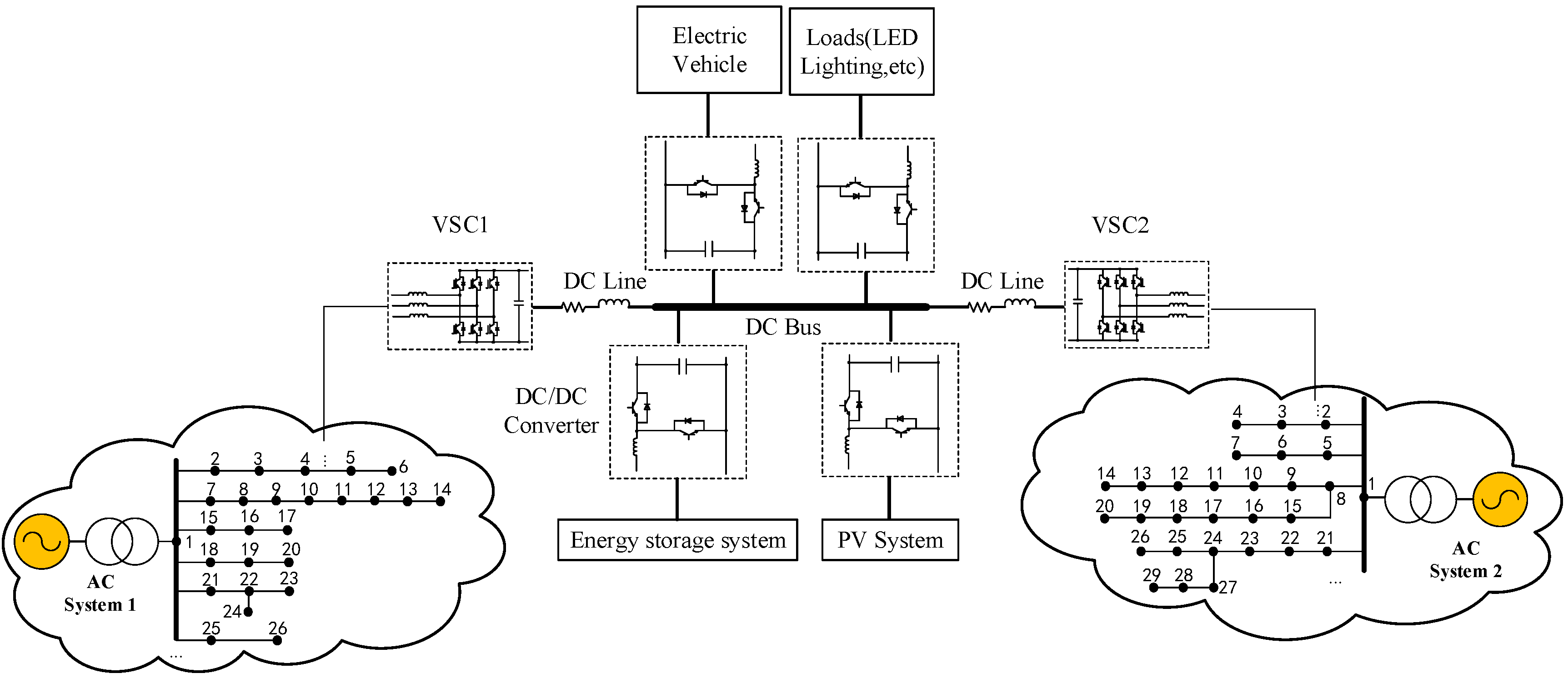
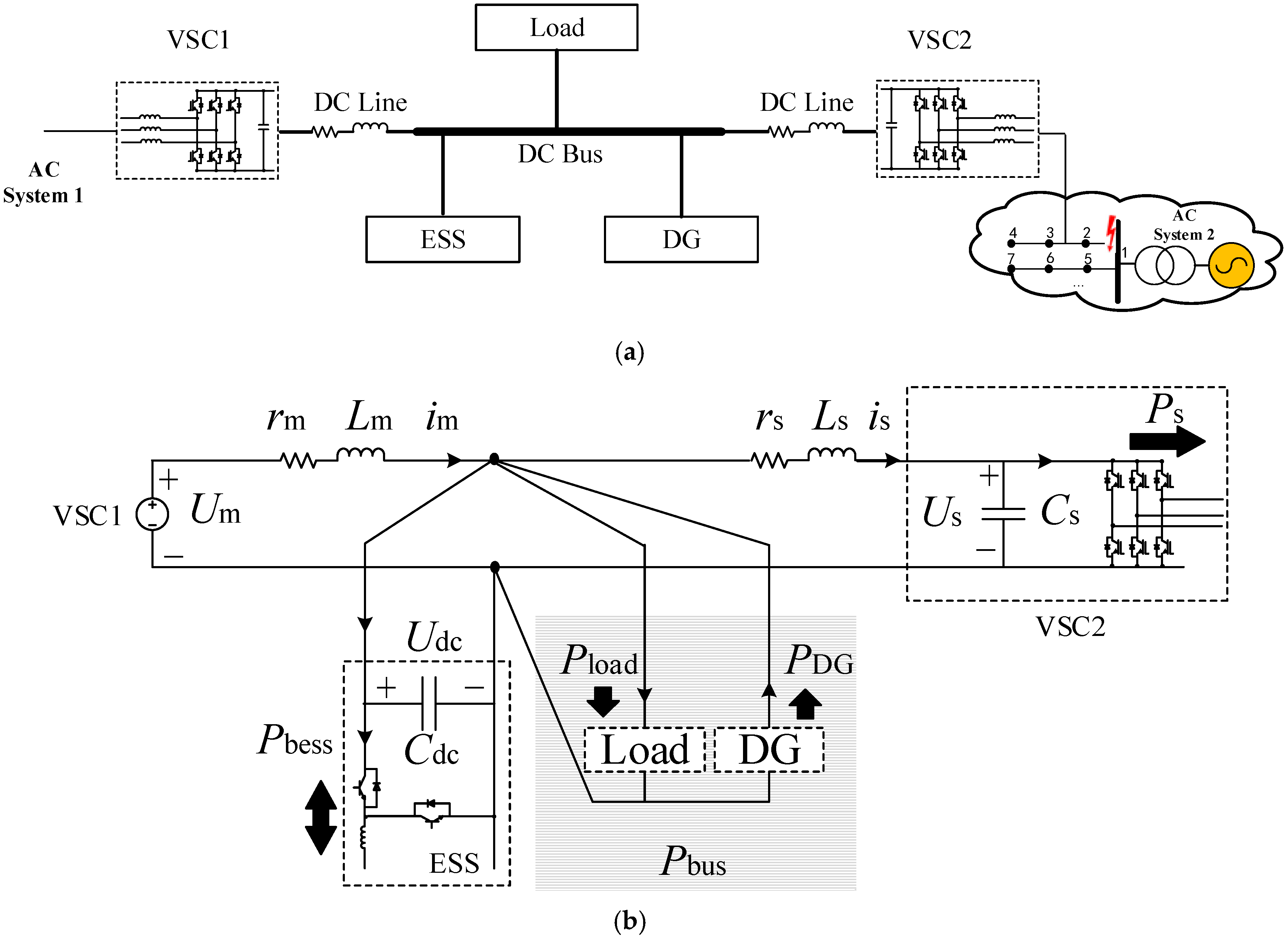
2. System Description

In the multi-terminal AC/DC system shown in Figure 1, AC systems 1 and 2 interconnect with each other via the DC network. The AC side of VSC1 and 2 connect to AC system 1 and AC system 2 respectively, and their DC sides feed into the DC bus through DC line. The DG, ESS, and electrical vehicle, can be integrated in the DC network, and their DC voltage can be adjusted by additional DC/DC converters while mismatching with the DC bus voltage. The energy flow on DC bus can consist of two parts: the part of energy production using PV system or ESS under discharge which arrives on DC bus, and the other part of the energy consumed by DC loads such as electrical vehicle, or ESS under charge. When the output power from the power generation unit is greater than the power absorbed by DC loads, the excess energy will be delivered to the AC systems through the multi-terminal DC structure. Otherwise, the AC systems will deliver power to the DC system.
Various control strategies can be applied to each VSC, such as the Udc control, the P&Q control, the V/f control, and the Droop control, as demonstrated in Figure 2.
If various control strategies are used for different VSCs, the multi-terminal system can work under the master–slave mode or peer-to-peer mode. The previous one chooses one VSC to be the master using the Udc control, who provides the constant DC voltage supply for DC bus. The rest of VSCs work as slaves applied with the P&Q control and following the power dispatching in order to realize the power flow transferring and balancing. The latter one implies that all the VSCs use the Droop control, and each one of them equilibrizes automatically the system’s power demand.
The master-slave mode is one of the most representable control techniques for the multi-terminal AC/DC system. If AC side of one VSC has malfunctions under this control mode, its circuit breakers or branch protection switches will turn off. In the case of an important or sensitive load connecting to the AC side, the uninterrupted power supply for the local AC load is needed, which means that this VSC has to quickly change from its original control strategy to the V/f control after the fault. Through this seamless switching method, the reliable and continuous power supply for local AC load is ensured. Under this circumstance, the output power of the VSC is determined by its AC-side local load. When the local AC load varies, its output power changes correspondingly. If observed from the DC network, its control mode can be seen as the P&Q control. The multi-terminal AC/DC system in Figure 1 is working under the master-slave mode, whereby the VSC1 operates as the master station which offers steady DC voltage supply and VSC2 runs as the slave station who accepts the power regulation. If the power loss of VSCs is neglected, when the AC system 2 has malfunctions, the equivalent circuit of the whole system with VSC2 supplying uninterrupted power supply for AC system, is shown in Figure 3.
In the shown system, VSC1 connects to the DC bus via DC line (rm, Lm); VSC2 connects to the DC bus via DC line (rs, Ls). ESS connects to the DC bus to provide fast power adjustment (The storage system proposed in this article is based on batteries, 20 Ah, 27 V Lithium battery module and the corresponding ESS are adopted). Um and im represent the DC-side voltage and current of VSC1 respectively. As the master station, the value of Um is normally considered as fixed. Us, is, Cs and Ps represent the DC-side voltage, current, capacitance and transfer power of VSC2 respectively. Udc and Cdc represent voltage and the equivalent capacitance of the DC bus. Pbess, Pload, and PDG represent respectively the ESS power, the load power, and the DG output power. Pbus is the equivalent load power in the DC bus which satisfies:
P b u s = P l o a d | P D G |
The power circuit of the system demonstrated in Figure 3 satisfies the following equations:
{ L m d i m d t = U m r m i m U d c L s d i s d t = U d c r s i s U s C d c d U d c d t = i m i s P b u s U d c C s d U s d t = i s P s U s

3. Power Transfer Capacity Analysis

After performing the small perturbation linearization on Equation (2), Equation (3) can be obtained:
[ Δ i m Δ i s Δ U d c Δ U s ] = [ r m L m 0 1 L m 0 0 r s L s 1 L s 1 L s 1 C d c 1 C d c 1 C d c P b u s U d c 0 U d c 0 0 0 1 C s 0 1 C s P s U s 0 U s 0 ] [ Δ i m Δ i s Δ U d c Δ U s ]
It can be known from Equation (3) that, under the certain structure of the multi-terminal AC/DC system, the stability of the system mainly depends on the mutual effect of Pbus and Ps. Both the equivalent load of the DC bus and VSC2 under the P&Q control have the negative impedance feature, which directly affecting the stable domain of system. This means that when Pbus changes, the maximum power transfer capacity of VSC2 also has relevant variation, in order to keep the system stable and vice versa. The system parameters are displayed in Table 1. The rated capacity of VSC2 is 180 kW and the corresponding Ps power transfer range is shown in Figure 4a (in this paper, the power flows out from the DC bus is considered as the positive direction).
As can be seen from Figure 4, when Pbus = −180 kW, the maximum transfer power of Ps is around 175 kW. With the diminution of the output power of Pbus, the maximum transfer power of Ps gradually decreases. After Pbus becomes absorbed power (Pbus > 0), with the augmentation of Pbus, the maximum transfer power of Ps continues to reduce. When Pbus = 180 kW, the maximum transfer power of Ps is approximately 45 kW. In Figure 4, the maximum transfer value of Ps gradually decreases from 175 kW to 45 kW. This tendency accords with the gradual decrease of system stable margin caused by the continuous increase of the load absorbed power (or the consistently reducing of the DG output power). At the same time, the actual power transfer capacity of VSC has significant reduction comparing to its rated value.
Based on the accumulated data from the classic operating condition, the equivalent load absorbed power from the DC bus is set to no more than 50 kW (Pbus = 50 kW), and its output power to the DC bus is less than 20 kW (Pbus = −20 kW). The corresponding Ps power transfer domain is shown in Figure 4b.
According to the system structure shown in Figure 3, the corresponding simulation model is established by MATLAB/Simulink, and the main parameters are presented in Table 1. The VSC1 is the master station and its rated capacity is 300 kW adopting the Udc control. The VSC2 is set as the slave station and its rated capacity is 180 kW using the P&Q control. Before the fault of AC system2 occurred, the AC side local load of VSC2 is 90 kW and the rated capacity of the ESS is 15 kW. When the fault happens, the protective relaying takes action, the switch on the upstream of VSC2 in AC system2 is been turned off, then VSC2 changes from the original control mode to the V/f control, which ensures the uninterrupted power supply for the local AC load. In this case, Ps = 90 kW.
The Figure 4b implies that when Pbus = 50 kW, the capacity of power transfer for Ps attains its minimum value and is approximately 97 kW. The system stable margin is relatively the lowest. Therefore, this operating point is chosen as the analytical object. The absorbed power of load is set to 100 kW (Pload = 100 kW), the output power of DG is 50 kW (PDG = −50 kW), at this point, the corresponding Pbus equals to 50 kW. The Figure 5 and Figure 6 describe the variation of DC voltage under the situation when the local load of AC side of VSC2 increases from 90 kW to 95 kW, and from 90 kW to 98 kW respectively at t = 2 s.
According to Figure 5, when the operating point (Pbus = 50 kW, Ps = 90 kW) changes to (Pbus = 50 kW, Ps = 95 kW), both the DC bus voltage and the DC-side voltage of VSC2 show obvious oscillation, however, they stabilize after approximately 2 s. In Figure 4, although (Pbus = 50 kW, Ps = 95 kW) approaches to the boundary of the power transfer, it has not yet entered the unstable area. The simulation result reveals that during the power variation, each DC voltage can stay stable after the rapid oscillation regulation, which corresponds to the conclusion of theoretical analysis.
The Figure 6 points out that when the operating point (Pbus = 50 kW, Ps = 90 kW) varies to (Pbus = 50 kW, Ps = 98 kW), the DC bus voltage and the DC-side voltage of VSC2 both have divergent oscillation until losing their stability. Judging by Figure 4, the operating point (Pbus = 50 kW, Ps = 98 kW) has already entered the instability area. The simulation result proves the theoretical analysis.

4. The Additional Control Method Based on Energy Storage System

When the DC network is configured with the ESS, it can provide quick power support for the multi-terminal AC/DC system. Hence it can realize various functions like emergency control, power oscillation damping and dynamic mutual voltage support, etc. At the same time, the contribution of the ESS to the multi-terminal AC/DC system depends on its configured capacity. Normally, the higher the rated capacity of the ESS is, the greater improvement it makes to the system performance, however, the relevant investment cost also gets higher. The configuration of the ESS results from a comprehensive consideration between control effect and the investment cost [23].
When the disturbance occurred in the multi-terminal AC/DC system, its state variable can be expressed as:
x = x o + Δ x
where x is the current value of the state variable, x o is its steady state value before the perturbation and Δ x is the disturbed value of the state variable. Then the following equation can be deduced from Equation (2):
[ x ] = A x + B u
With:
x = [ Δ i m Δ i s Δ U d c Δ U s ] A = [ r m L m 0 1 L m 0 0 r s L s 1 L s 1 L s 1 C d c 1 C d c 0 0 0 1 C s 0 0 ] B = [ 0 0 1 C d c 0 ] P b u s U d c o ( U d c o + Δ U d c ) Δ U d c
Assuming that P and Q are both positive definite symmetric matrix and P is the solution of the Lyapunov equation [24]:
P A + A t P + Q = 0
The design of the additional feedback control of the ESS is demonstrated in Equation (7):
u = B t P x
In order to improve power transfer capacity with low cost, the design of the additional control strategy based on the ESS is shown in Figure 7. This implies that on the basis of the current controller, the additional current instruction value iadd represented in Equation (8) is superposed:
i a d d = u u
As shown in Figure 7, the additional control strategy first acquires the operating information of the multi-terminal AC/DC system, such as DC currents and voltages. By means of these data, the u is generated from the state-space model in Equation (5). Then after solving and obtaining the positive definite symmetric matrix P, with the help of matrix B, u’ can be calculated from the Equation (7). Based on the above variables, the additional current instruction value iadd formed by Equation (8) is sent to the ESS to improve the power transfer capacity of the multi-terminal AC/DC system through the additional control, without changing the existing structure of the ESS controller and its parameters.

5. Analysis and Verification

5.1. Analysis of the Improvement of Power Transfer Capacity

Figure 8 describes the power transfer boundary of the multi-terminal AC/DC system with the ESS, and after being performed by the additional control strategy with Pbus changing from −20 kW to 50 kW (The parameters for calculation is the same as in Table 1). Comparing Figure 4b and Figure 8, it can be known that after applying the additional control, the power transfer boundary of Ps is significantly improved. Taking Pbus = 50 kW as an example, the maximum transfer power of Ps after applying the additional control based on the ESS is around 183 kW, however, it is about 97 kW without the additional control, which has an improvement of almost 90%. This implies that the damping ability can be provided by additional control based on the ESS in the multi-terminal AC/DC system. Therefore, the power transfer capacity of VSC2 can be expanded effectively. This control method can also stabilize some operating points which would lose its stability before applying the additional control.

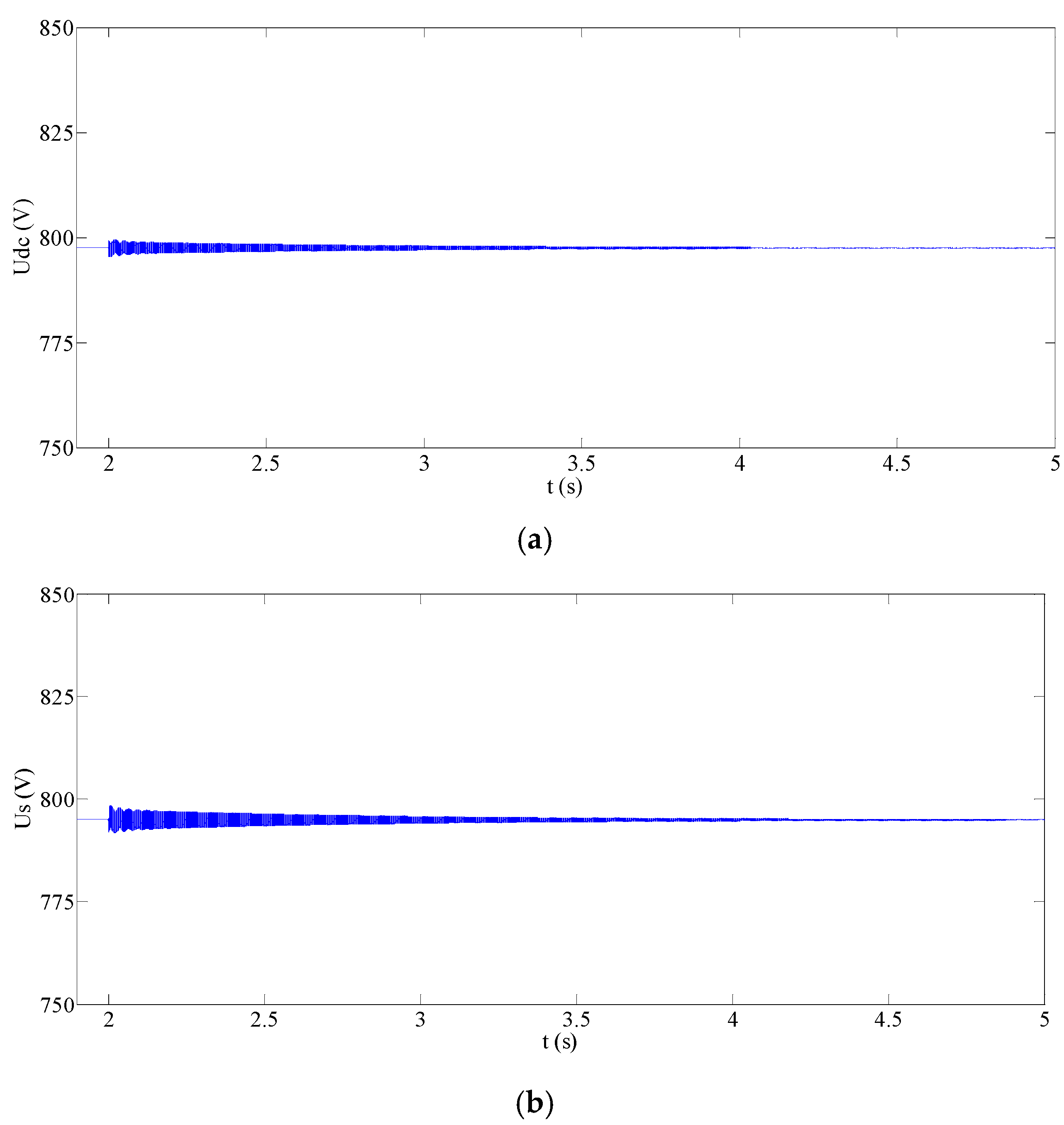
5.2. Simulation Verification

Performing the addition control on the simulation model built in the part 3 and still choosing Pbus = 50 kW as the analytical object, Figure 9 and Figure 10 describes the variation of the DC voltages under the circumstance when the local load in AC side of VSC2 augments at t = 2 s which means that Ps rises from 90 kW to 100 kW, 120 kW, 150 kW, and 180 kW respectively.
As can be seen from Figure 9, when Ps changes from 90 kW to 100 kW, 120 kW, 150 kW and 180 kW, Udc can quickly become stable after short-time oscillation with small amplitude. Among all the situations, the one that increasing from 90 kW to 100 kW causes the least undulation of the amplitude of Udc and the shortest recovering time to return to its steady state. The maximum fluctuation of Udc is less than +0.31% and −0.49% of its stabilized value. Whereas the variation of Ps from 90 kW to 180 kW leads to the highest amplitude undulation of Udc and the longest steady-state recovering time. The maximum fluctuation of Udc is no more than +3.81% and −4.93% of its stabilized value. The simulation result proves that when Ps changes, the higher the transfer power goes, the acuter the oscillation of Udc is, the larger the fluctuation range is, and the longer time it takes to regain its stability.
Figure 10 is similar to Figure 9, under four different situations of Ps variation, as Us quickly stabilizes after oscillation with small amplitude. When Ps changes, the higher the transfer power is, the more drastic the oscillation of Us is, and the longer the steady-state recovering time is.
Comparing these two pictures, it is worth noting that under the same variation of Ps, Us has more evident oscillation, bigger undulation of the amplitude, and longer steady-state recovering time than Udc. All the operating points (Pbus = 50kW, Ps = 100kW), (Pbus = 50kW, Ps = 120 kW), (Pbus = 50 kW, Ps = 150 kW), (Pbus = 50 kW, Ps = 180 kW) in Figure 4 are in the unstable area. When the multi-terminal AC/DC system is configured with the ESS and the additional control strategy, then these points all appear in the stable area. Combining the simulation results in Figure 9 and Figure 10, it is worth noting that when Pbus equals to 50 kW, increasing the transfer power of Ps to 100 kW,120 kW, 150 kW, and 180 kW causes only small undulation of the DC voltage. The whole system can stay stable and would not affect the normal operation of all devices/loads. This observation matches the theoretical analysis for the stable domain.
When the local load in AC side of VSC2 changes, the transfer power of Ps varies correspondingly. After applying the additional control, the ESS will dynamically generate the corresponding instruction value for the additional current during the voltage changes and realize the rapid oscillation damping to ensure the whole stability. Figure 11 describes the additional power of the ESS during simulation.
Under four different changes of Ps, the additional power of the ESS Pbess (Pbess = iadd × Udc) can quickly reach its steady state through the short-time regulation. Among these situations, the undulation amplitude of Pbess is the smallest when Ps changes from 90 kW to 100 kW and the steady-state recovering time is also the shortest. The largest fluctuation range of Pbess is less than +0.98% and −1.37% of the transferred power and its stablized value is only 75 W which is less than 0.08% of the transferred power. The undulation amplitude of Pbess attains its maximum when Ps increases from 90 kW to 180 kW and it takes the longest time to reach its stable status. The largest fluctuation range of Pbess is less than +5.86% and −7.04% of the transferred power and its steady value is only 680W which is less than 0.38% of the transfer power. This implies that under these four operating conditions, the undulation amplitude of the additional power during the regulation process of the ESS is smaller comparing to the requested transfer power of VSC2. The steady-state value after stabilization is very small which means that the cost paid by the ESS using the additional control in order to improve the system power transfer capacity is low.
Figure 12 describes the analytical results under Ps changes from 90 kW to 100 kW–180 kW (each 5 kW is an interval). From 12a, Udc can stay stable under all the different operating conditions mentioned above and their steady-state values are approximately constant. The amplitude of fluctuation is all within ±4.93% of their steady-state values during the regulation process. Figure 12b shows that Us can remain stable under all situation and their steady-state values are nearly the same with each other. During regulation, the fluctuating range of Us is all within ±7.35% of their steady-state value. By comparing the two subfigures, the fluctuation amplitude of Us is always larger than that of Udc during regulation process under the same power transfer variation.
Figure 12c implies that under all circumstances, the variation of the steady-state value of Pbess is small. Moreover, the ratio of each value to its corresponding transferred power of Ps is less than 0.38%. During the regulation process, the amplitude of undulation of Pbess is all within ±7.04% of its corresponding transferred power.
Figure 12d implies that under the same variation of transfer power, the time to regain its steady-state of Udc is the shortest, followed by that of Us and the time of the additional power for the ESS to reach its stable status is the longest. At the same time, the recovering time of Udc, Us and Pbess get longer with the gradual augmentation of the transferred power of Ps, however these three can all get back to their steady-state within 1.5 s.
Thus, after the multi-terminal AC/DC system implements with the ESS and performs the additional control strategy, the system will be able to overcome the limitation of the power transfer for all VSCs caused by different factors such as the negative impedance feature and the resonance characteristic of DC network, etc., therefore improving the power transfer capacity and the mutual support ability of each terminal, and at the same time ensuring the stability of the DC voltage and the continuous power supply for the important load on the AC side under AC system fault. The additional control achieves the safe and reliable operation of the multi-terminal AC/DC system under complicate working condition.

5.3. Economic Analysis of the Energy Storage System

This paper improves the power transfer capacity of VSC by implementing the ESS to the DC bus of the multi-terminal AC/DC system and using the additional control strategy. The capacity of the ESS usually needs to find a compromise between the control effect and the investment cost. The cost for adding the ESS to the system is mainly including the DC/DC converts and the batteries. In order to have significant improvement of the power transfer capacity for VSC, the method of additional control technique proposed in this paper or the traditional configuration method can be used. The latter one indicates that the difference of the power transfer capacity before and after the improvement can be supported by the capacity expansion of the power converter of the ESS.
Choosing Pbus = 50 kW (The maximum value of Ps is around 97 kW as shown in Figure 4b) as the analytical object, Table 2 and Table 3 describes respectively the economic comparison of improving the power transfer capacity of Ps for DC/DC converter, and batteries using the proposed method in this paper and the traditional one.
The result in Table 2 shows that the additional control for improving the power transfer capacity of Ps proposed in this paper can effectively reduce the power capacity of DC/DC converters for the the ESS. Moreover, with the growing of the power transfer capacity of Ps, the investment cost saving effect of the converter becomes more conspicuous. When Ps reaches its rated value, the method proposed in this paper can save approximately 85% of the investment cost compared to the traditional one.
The result in Table 3 shows that by applying the additional control techniques on the ESS, just a few additional power and damping energy provided by the ESS can achieve notable improvement of the power transfer capacity of the system. If Ps rises from 97 kW to 100 kW and keeps running for 1 h, only 0.076 kWh storage batteries is requested. When Ps satisfies its rated power and continues to operate for 1 h, 0.678 kWh batteries is sufficient. Comparing to the traditional method, the proposed technique can save the cost of storage batteries for about 99%.
Overall, the cost of applying the additional control based on the ESS is very low, but its ability of improving the system power transfer capacity is remarkable.

5.4. Sensitivity Analysis and Contribution Discussion

Equation (6) shows that when the A and B matrices are fixed, the P matrix will be determined by the Q matrix. So, the performance of the addition control depends on the Q matrix. The Q matrix is the positive definite symmetric matrix, and it is usually chosen equal to k*In with In being the nth-order identity matrix. k is the important weighting parameters in the matrix Q, and the different values of k at different positions in In will lead to a change in the feedback control laws, which further affects the contribution of the additional control to the improvement of system power transfer boundary. Figure 13 describes a sensitivity analysis of the weighting parameters of the control strategy, compared to a relevant baseline with n = 4 and k = 0.01.
Figure 13 implies that under the same change range [0.01 0.016], the improvement of the power transfer boundary under the weighting parameters change at Q[1,1] is the most significant, then followed by change at Q[2,2], and the smallest when change at Q[3,3]. Taking Pbus = 50 kW as an example, the maximum transfer power of Ps after applying the additional control based on the ESS is around 215 kW, 185 kW, 180 kW, and 183 kW under the weighting parameters change at Q[1,1], Q[2,2], Q[3,3], Q[4,4], respectively. From the sensitivity analysis, designing a reasonable matrix Q, especially Q[1,1], is an important foundation for improving the performance of the additional control and expanding system power transfer boundary.

6. Conclusions

This paper aims at the multi-terminal AC/DC system, builds its corresponding equivalent circuit and the state-space model, and analyses the system power transfer capacity. On the basis of that, this paper proposes an additional control technique based on the ESS with low cost to improve the power transfer capacity and performs the corresponding test and verification. The main conclusion is summarized in the following statements:
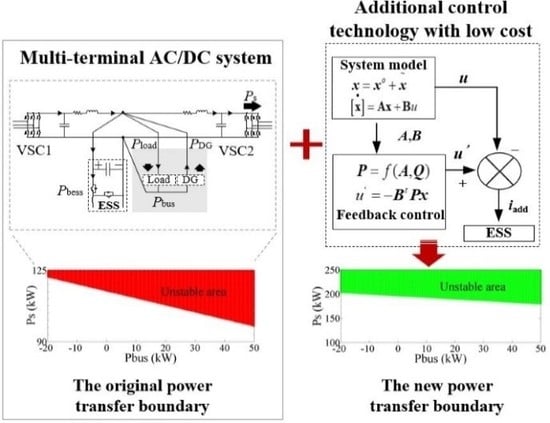
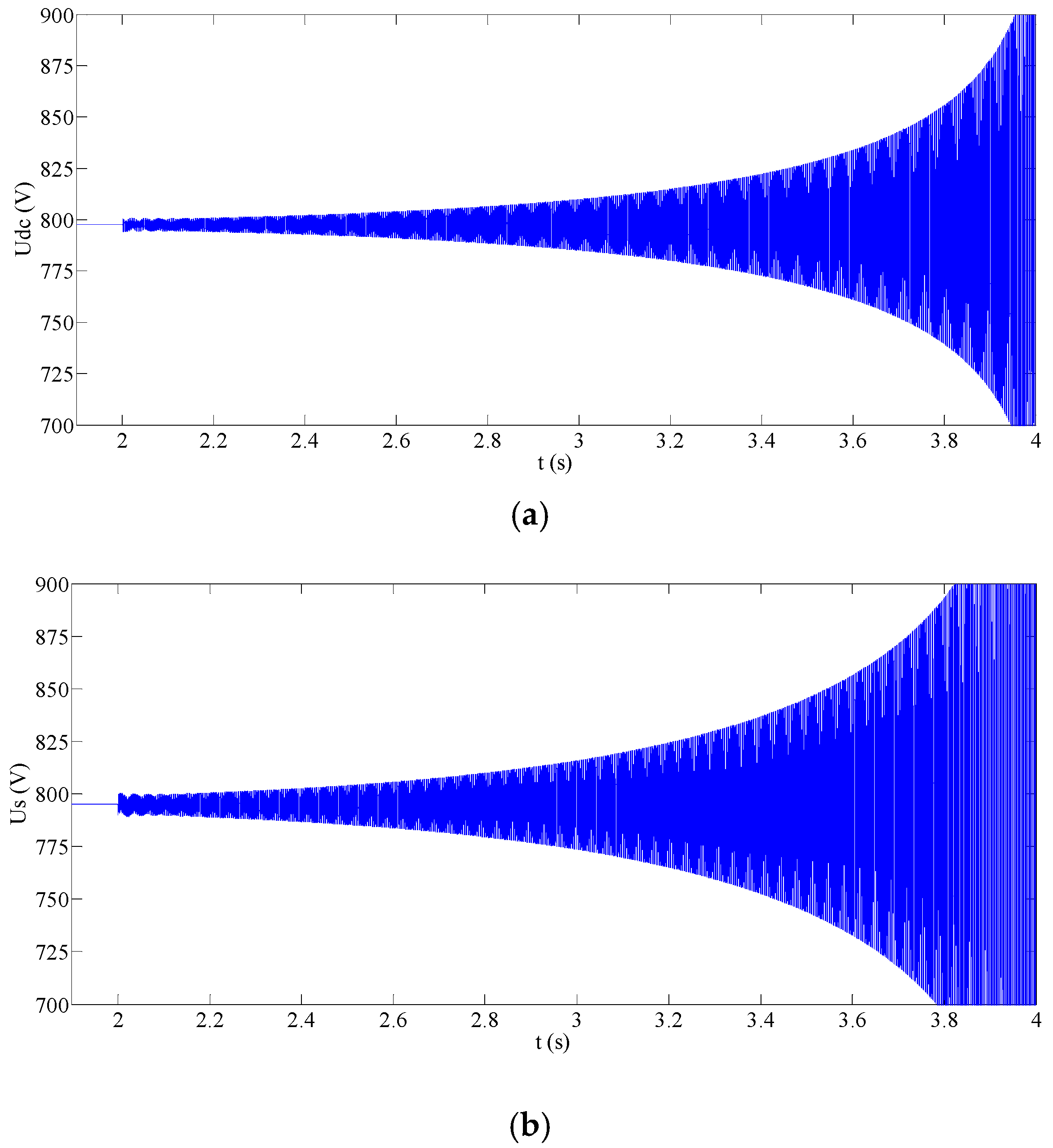
  • Due to the different factors such as negative impedance feature and DC network resonance, the actual power transfer capacity of AC/DC system could be sharply lower than its rated capacity which leads to remarkable shrink of the system power transfer boundary and lowers the economics of the whole system.
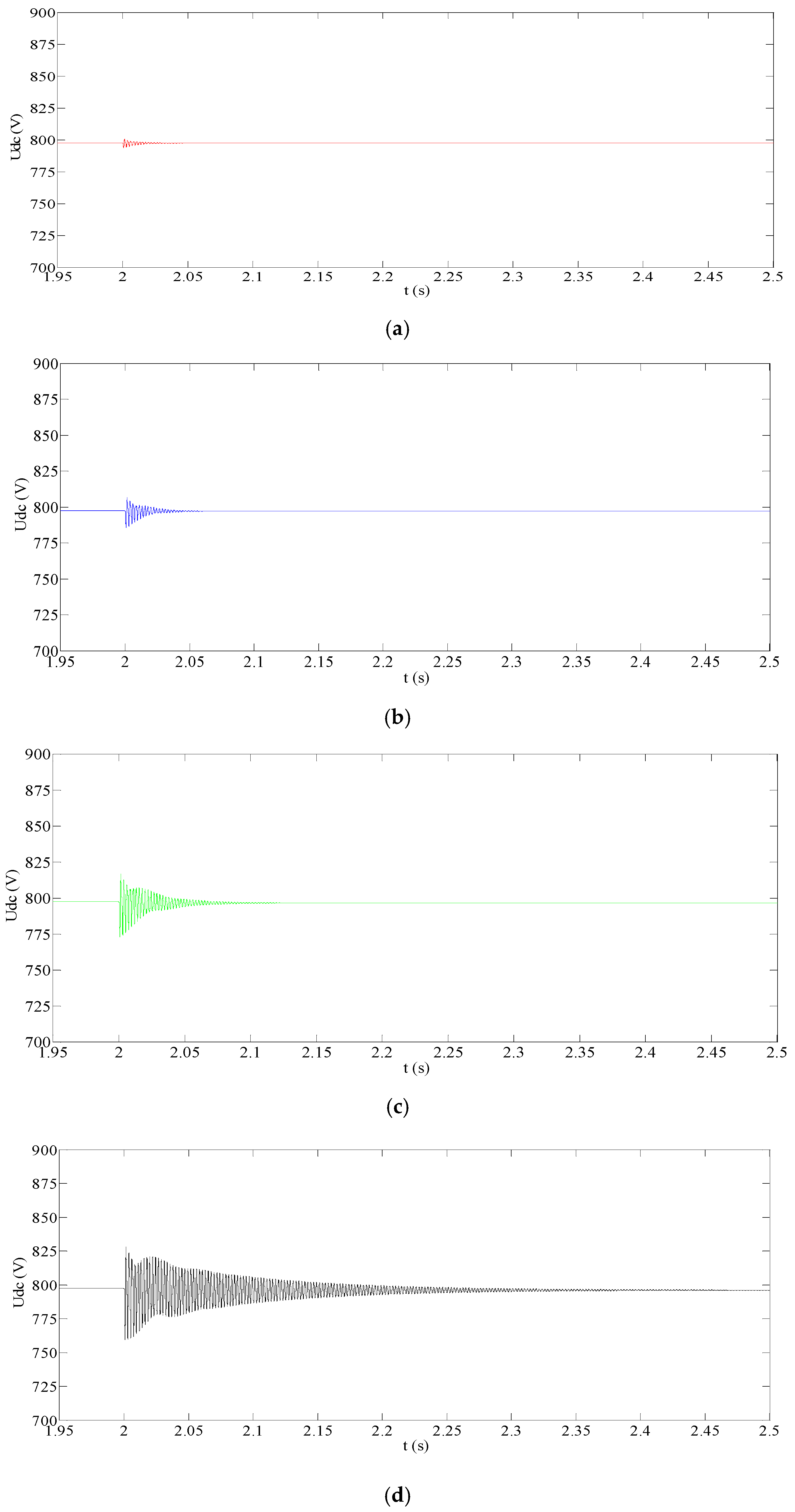
  • Using the additional control technique does not have to get involved or change the structure of the current control system of the ESS. By using only the additional instruction given by the dynamic feedback control, the power transfer capacity can be effectively improved to its rated capacity and at the same time ensure the DC voltages and the ceaseless power supply for the important load under the disturbance of the AC system fault.
  • When the system is equipped with the ESS, using additional control method can save more investment cost of the DC/DC converters and the batteries than the traditional method. The cost for realizing the purpose, such as improving the transfer power of VSC to its rated value and notably expanding the system power transfer boundary, is quite low.

Author Contributions

Conceptualization, Z.W. and L.L.; methodology, Y.Y.; formal analysis, X.Y.; data curation, C.Z.; writing—original draft preparation, W.D.; writing—review and editing, W.P.; project administration, L.K. All authors have read and agreed to the published version of the manuscript.

Funding

This research was supported by the National Key Research and Development Program of China (2017YFB0903300).

Conflicts of Interest

The authors declare no conflict of interest.

References

  1. Liu, X.; Wang, P.; Loh, P.C. A hybrid AC/DC microgrid and its coordination control. IEEE Trans. Smart Grid 2011, 2, 278–286. [Google Scholar]
  2. Wu, H.; Locment, F.; Sechilariu, M. Experimental Implementation of a Flexible PV Power Control Mechanism in a DC Microgrid. Energies 2019, 12, 1233. [Google Scholar] [CrossRef] [Green Version]
  3. Baek, J.; Choi, W.; Chae, S. Distributed Control Strategy for Autonomous Operation of Hybrid AC/DC Microgrid. Energies 2017, 10, 373. [Google Scholar] [CrossRef] [Green Version]
  4. Peyghami, S.; Mokhtari, H.; Blaabjer, F. Autonomous operation of a hybrid ac/dc microgrid with multiple interlinking converters. IEEE Trans. Smart Grid 2017, 9, 6480–6488. [Google Scholar] [CrossRef] [Green Version]
  5. Davari, M.; Mohamed, Y.A.R.I. Robust multi-objective control of VSC-based DC-voltage power port in hybrid AC/DC multi-terminal micro-grids. IEEE Trans. Smart Grid 2013, 4, 1597–1612. [Google Scholar] [CrossRef]
  6. Broyevich, D.; Cvetkovic, I.; Dong, D.; Burgos, R.; Wang, F.; Lee, F. Future electronic power distribution systems: A contemplative view. In Proceedings of the 2010 12th International Conference on Optimization of Electrical and Electronic Equipment, Basov, Russia, 20–22 May 2010; pp. 1369–1380. [Google Scholar]
  7. Liang, Z.; Guo, R.; Li, J.; Huang, A.Q. A high-efficiency PV module-integrated DC/DC converter for PV energy harvest in FREEDM systems. IEEE Trans. Power Electron. 2011, 26, 897–909. [Google Scholar] [CrossRef]
  8. Kakigano, H.; Miura, Y.; Ise, T. Low-voltage bipolar-type DC microgrid for super high quality distribution. IEEE Trans. Power Electron. 2010, 25, 3066–3075. [Google Scholar] [CrossRef]
  9. Bifaretti, S.; Zanchetta, P.; Watson, A.; Tarisciotti, L.; Clare, J.C. Advanced power electronic conversion and control system for universal flexible power management. IEEE Trans. Smart Grid 2011, 2, 231–243. [Google Scholar] [CrossRef]
  10. Liu, G.; Zhao, Y.; Yuan, Z. Study on demonstration project technical scheme of VSC-DC distribution system in Shenzhen. South. Power Syst. Technol. 2016, 10, 1–7. [Google Scholar]
  11. Chen, A. Coordination control and mode switching strategy for hybrid AC/DC microgrid with multi-bus structure. Autom. Electr. Power Syst. 2018, 42, 175–183. [Google Scholar]
  12. Rahimi, A.M.; Emadi, A. Active damping in DC/DC power electronic converters: A novel method to overcome the problems of constant power loads. IEEE Trans. Ind. Electron. 2009, 56, 1428–1439. [Google Scholar] [CrossRef]
  13. Magne, P.; Nahid-Mobarakeh, B.; Pierfederici, S. General active global stabilization of multiloads DC-power networks. IEEE Trans. Power Electron. 2012, 27, 1788–1798. [Google Scholar] [CrossRef]
  14. Areerak, K.; Sopapirm, T.; Bozhko, S.; Hill, C.I.; Suyapan, A.; Areerak, K. Adaptive stabilization of uncontrolled rectifier based AC-DC power systems feeding constant power loads. IEEE Trans. Power Electron. 2018, 33, 8927–8935. [Google Scholar] [CrossRef] [Green Version]
  15. Jamshidpour, E.; Nahid-Mobarakeh, B.; Poure, P.; Pierfederici, S.; Meibody-Tabar, F.; Saadate, S. Distributed Active Resonance Suppression in Hybrid DC Power Systems Under Unbalanced Load Conditions. IEEE Trans. Power Electron. 2013, 28, 1833–1842. [Google Scholar] [CrossRef] [Green Version]
  16. Deng, W.; Pei, W.; Li, L.Y. Active stabilization control of multi-terminal AC/DC hybrid system based on flexible low-voltage DC power distribution. Energies 2018, 11, 502. [Google Scholar] [CrossRef] [Green Version]
  17. Marx, D.; Magne, P.; Nahid-Mobarakeh, B.; Pierfederici, S.; Davat, B. Large signal stability analysis tools in DC power systems with constant power loads and variable power loads—A review. IEEE Trans. Power Electron. 2012, 27, 1773–1787. [Google Scholar] [CrossRef]
  18. Sulligoi, G.; Bosich, D.; Giadrossi, G.; Zhu, L.; Cupelli, M.; Monti, A. Multiconverter medium voltage DC power systems on ships: Constant-power loads instability solution using linearization via state feedback control. IEEE Trans. Smart Grid 2014, 5, 2543–2552. [Google Scholar] [CrossRef]
  19. Li, L.; Pei, W.; Deng, W.; Kong, L. Active Damping Strategy for Improving VSC and Line Interaction Instability in DC Distribution Network. High Volt. Eng. 2019, 45, 2884–2894. [Google Scholar]
  20. Tehrani, K.A.; Capitaine, T.; Barrandon, L.; Hamzaoui, M.; Rafiei, S.M.R.; Lebrun, A. Current control design with a fractional-order PID for a three-level inverter. In Proceedings of the 2011 14th European Conference on Power Electronics and Applications, Birmingham, UK, 30 August 2011; Volume 1, pp. 1–7. [Google Scholar]
  21. El Yakine Kouba, N.; Menaa, M.; Hasni, M.; Tehrani, K.; Boudour, M. A novel optimized fuzzy-PID controller in two-area power system with HVDC link connection. In Proceedings of the 2016 International Conference on Control, Decision and Information Technologies (CoDIT), St. Julian’s, Malta, 6–8 April 2016; Volume 1, pp. 204–209. [Google Scholar]
  22. Tehrani, K.A.; Amirahmadi, A.; Rafiei, S.M.R.; Griva, G.; Barrandon, L.; Hamzaoui, M.; Rasoanarivo, I.; Sargos, F.M. Design of fractional order PID controller for boost converter based on multi-objective optimization. In Proceedings of the 14th International Power Electronics and Motion Control Conference EPE-PEMC 2010, Ohrid, Macedonia, 6–8 September 2010; Volume 3, pp. 179–185. [Google Scholar]
  23. Wang, H.; Wang, T.; Xie, X.; Ling, Z.; Gao, G.; Dong, X. Optimal Capacity Configuration of a Hybrid Energy Storage System for an Isolated Microgrid Using Quantum-Behaved Particle Swarm Optimization. Energies 2018, 11, 454. [Google Scholar] [CrossRef] [Green Version]
  24. Khalil, H. Nonlinear Systems, 3rd ed.; Prentice-Hall, Inc.: Upper Saddle River, NJ, USA, 2002. [Google Scholar]
Figure 1. Typical structure of the multi-terminal AC/DC system.
Energies 13 00495 g001
Figure 2. Classic VSC control strategies.
Energies 13 00495 g002
Figure 3. System structure and the equivalent circuit. (a) System structure under failure at one VSC; (b) Equivalent circuit.
Energies 13 00495 g003
Figure 4. The power transfer boundary. (a) Pbus from −180 kW to 180 kW; (b) Pbus from −20 kW to 50 kW.
Energies 13 00495 g004
Figure 5. The simulation result when Ps changes from 90kW to 95kW: (a) The DC bus voltage; (b) The DC-side voltage of VSC2.
Energies 13 00495 g005
Figure 6. The simulation result when Ps changes from 90kW to 98kW: (a) The DC bus voltage; (b) The DC-side voltage of VSC2.
Energies 13 00495 g006
Figure 7. Additional control strategy.
Energies 13 00495 g007
Figure 8. The power transfer boundary after applying the additional control based on the ESS.
Energies 13 00495 g008
Figure 9. Simulation results of Udc: (a) Ps changes from 90 kW to 100 kW; (b) Ps changes from 90 kW to 120 kW; (c) Ps changes from 90 kW to 150 kW; (d) Ps changes from 90 kW to 180 kW.
Energies 13 00495 g009
Figure 10. Simulation results of Us: (a) Ps changes from 90 kW to 100 kW; (b) Ps changes from 90 kW to 120 kW; (c) Ps changes from 90 kW to 150 kW; (d) Ps changes from 90 kW to 180 kW.
Energies 13 00495 g010
Figure 11. The curves of the additional power of the ESS: (a) Ps changes from 90 kW to 100 kW; (b) Ps changes from 90 kW to 120 kW; (c) Ps changes from 90 kW to 150 kW; (d) Ps changes from 90 kW to 180 kW.
Energies 13 00495 g011
Figure 12. The performance comparison with the implementation of the addition control: (a) DC bus voltage; (b) DC-side voltage of VSC2; (c) The additional power of the ESS; (d) The steady-state recovering time.
Energies 13 00495 g012
Figure 13. The sensitivity analysis of the weighting parameters: (a) The power transfer boundary under different values of k at Q[1,1]; (b) The power transfer boundary under different values of k at Q[2,2]; (c) The power transfer boundary under different values of k at Q[3,3]; (d) The power transfer boundary under different values of k at Q[4,4].
Energies 13 00495 g013aEnergies 13 00495 g013b
Table 1. Parameters of the multi-terminal AC/DC system.
SymbolValueSymbolValue
rm0.0137 Ωrs0.0219 Ω
Lm0.0670 mHLs0.1073 mH
Cdc1100 µFCs500 µF
Um800 VPbus−20 kW–50 kW
Table 2. Power capacity comparison of DC/DC converter of the ESS.
Power Transfer Boundary after Improvement(kW)Capacity Needed Using the Traditional Method (kW)Capacity Needed Using the Proposed Method (kW)Economical Saving (%)
1003.001.3754.33
12023.04.1581.96
15053.008.3684.23
18083.0012.6884.72
Table 3. Energy capacity comparison of batteries of the ESS (Run for 1 h).
Power Transfer Boundary after Improvement (kW)Capacity Needed Using the Traditional Method (kWh)Capacity Needed Using the Proposed Method (kWh)Economical Saving (%)
Transient StateSteady State
1003.004.57 × 10−50.07697.46
12023.02.53 × 10−40.22699.02
15053.009.29 × 10−40.45199.15
18083.005.35 × 10−30.67899.18

