Article

Thermophysical Properties Characterization of Sulphoaluminate Cement Mortars Incorporating Phase Change Material for Thermal Energy Storage

School of Civil Engineering and Architecture, Xi’an University of Technology, Xi’an 710048, China
*
Author to whom correspondence should be addressed.
Energies 2020, 13(19), 5024; https://doi.org/10.3390/en13195024
Submission received: 2 August 2020 / Revised: 13 September 2020 / Accepted: 22 September 2020 / Published: 24 September 2020

Abstract

:
Efficient use of solar energy by thermal energy storage composites and utilizing environmentally friendly cementitious materials are important trends for sustainable building composite materials. In this study, a paraffin/low density polyethylene (LDPE) composite shape-stabilized phase change material (SSPCM) was prepared and incorporated into a sulphoaluminate cement (SAC) mortar to prepare thermal energy storage mortar. The thermal and mechanical properties of SSPCM and a SAC-based thermal energy storage material (SCTESM) were investigated. The result of differential scanning calorimeter (DSC) analysis indicates that the latent heat of SCTESM is as high as 99.99 J/g. Thermogravimetric analysis demonstrates that the SCTESM does not show significant decomposition below 145 °C. The volume stability test shows the volume shrinkage percentage of the SCTESM is less than that of pure SAC mortar and far less than that of ordinary Portland cement mortar. The SCTESM has high early strength so that the compressive strength at 1-, 3-, and 7-day curing age is up to that at 28-day curing age of 67.5%, 78.3%, and 86.7%, respectively. Furthermore, a mathematical prediction model of the SCTESM compressive strength was proposed. The investigation of latent heat storage characteristics and the thermoregulating performance reveals that SCTESMs have the excellent capacity of heat storage and thermoregulating.

1. Introduction

In the last decade, the environmental impact of the building sector is of increasing concern, particularly the effects of environmental pollution, global warming, and greenhouse gas emissions. Over this period, more than 30% fossil fuels were consumed by the building sector [1]. This proportion is higher in developing countries than that of the developed countries [2]. Thermal energy storage technology is efficiently deployed to reduce fossil energy consumption and improve the quality of indoor thermal environment in buildings. Due to their excellent heat storage capacity, phase change materials (PCMs) have a wide range of applications in building thermal energy storage. PCMs store excess thermal energy in daytime and release heat at night, thus matching the indoor energy supply and demand of heating buildings [3].
Although a variety of PCMs are available, paraffin is still considered as a dominant candidate because of its high latent heat, chemical inactivity, nonsegregation, and safety [4,5,6]. However, as a solid–liquid PCM, there is a risk of liquid paraffin leakage during its phase transition. Preparing shape-stabilized phase change materials (SSPCMs) is an effective method to prevent leaking. Many researchers employed porous materials to absorb melted PCMs in a vacuum to form shape stabilized PCMs [7,8] or employed a thin and sealed polymeric film to microencapsulate PCMs to avoid leakage [9,10]. However, these highly specialized preparations of SSPCMs are characterized by high technology and high cost, which are not conducive to the wide application of PCMs. A simplified method to prepare SSPCM by mixing melted PCM and melted polymer has provided the inspiration to develop a composite PCM. Zhang et al. [11] prepared a paraffin/polyethylene composite PCM by mixing and co-heating. The study confirmed that the polymer network retained its shape to support the paraffin in either liquid or solid phase. Employing polyethylene as a supporting material and myristic acid as a solid–liquid PCM, Tang et al. [12] successfully developed a SSPCM with 180 °C operating temperature using a similar method. Such a SSPCM can overcome the shortcomings of traditional PCMs.
Incorporating shape-stabilized paraffin within building materials is a convenient way to enable its application in construction. Many studies [13,14] have developed thermal energy storage composites prepared by incorporating SSPCMs into cement-based materials. Such cement-based thermal energy storage composites have traditionally employed ordinary Portland cement (OPC) with high carbon dioxide (CO2) emissions as the binder. Previous studies [15,16] confirmed that approximately 0.66–0.82 kg of CO2 equivalent was emitted for every kilogram of OPC manufactured, and the cement industry accounts for 7% of the entire world CO2 emissions. Alternative cements to OPC that are aimed at reducing greenhouse gas emissions have received increasing attention in recent years. As environmental protection is highly valued, the research and application of sulphoaluminate cement (SAC) have attracted more and more attention in recent years, because the carbon dioxide emissions in the production process are less than that of OPC [17,18]. The SAC is mainly composed of ye’elimite ( C 4 A 3 S ¯ ), followed by a small amount of belite ( C 2 S ), tetracalcium alumino-ferrite ( C 4 AF ), gehlenite ( C 2 AS ), tricalcium aluminate ( C 3 A ), and gypsum ( C S ¯ H 2 ), etc. [17]. The major hydration products of SAC such as ettringite (AFt), mono-sulfuraluminate (AFm), aluminum and hydroxide (AH3) can be rapidly generated early in the hydration process (Equations (1) and (2)).
C 4 A 3 S ¯ + 18 H C 3 A · C S ¯ · 12 H + 2 AH 3   ( AFm   generation )
C 4 A 3 S ¯ + 2 C S ¯ H 2 + 34 H C 3 A · 3 C S ¯ · 32 H + 2 AH 3       ( AFt   generation )
The rapid generation of Aft, AFm, and AH3 causes SAC to have the advantages of fast strength growth and small volume shrinkage [19,20]. This result suggests that using SAC as the matrix can improve the early strength of SAC-based thermal energy storage material (SCTESM). SAC has been standardized in China for decades, effectively promoting SAC production and engineering applications. Nevertheless, to the best of our knowledge, there are few studies on employing SAC mortar to incorporate PCM for developing thermal energy storage composites.
In this paper, a SCTESM was explored and its thermophysical properties were investigated. PCMs used in passive solar heating buildings need to have a suitable phase transition temperature to maximize thermal energy storage and improve indoor thermal comfort. In solar passive heating buildings, indoor air temperature in winter usually varies from 20 °C and above during daytime to about 10 °C and below at night [21]. Therefore, paraffin with a phase transition temperature around 20 °C was selected for this study. Low density polyethylene (LDPE) was selected and employed as a supporting material to form shape-stabilized paraffin. SAC mortar was employed as the matrix to incorporate the SSPCM. In this paper, the mass fraction of SSPCM (with respect to cement) is up to 50%, which is significantly higher than the amount of PCM incorporated into cement mortar in previous investigations [22]. This research focused on the thermophysical properties and mechanical properties of SCTESM that are rarely reported in existing literature.

2. Experiment

2.1. Materials

Grade 42.5 SAC, which complies with the National Norms of China GB 20472-2006, was used as the matrix material and its properties of setting time and strength were reported in our previous published literature [23].
Paraffin, LDPE, and flake graphite were used together to prepare SSPCM. Paraffin with phase transition temperature of about 20 °C was employed to act as PCM. LDPE with a melting point of 150 °C was adopted as shape support material for SSPCM (shown in Figure 1). Graphite was used as a thermal conductivity reinforcing material of the composite PCM (SEM of graphite shown in Figure 2).
Polycarboxylate superplasticizer MELFLUX 2651F was used as an additive to adjust the workability of the SCTESM slurry to ensure that the casting conditions of all samples were consistent. The China ISO standard sand was used as the fine aggregate.

2.2. Preparation of SCTESM

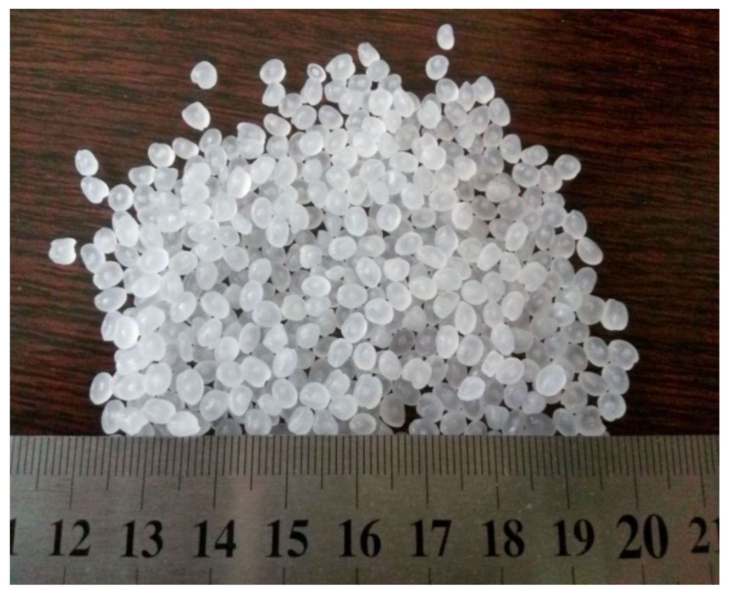
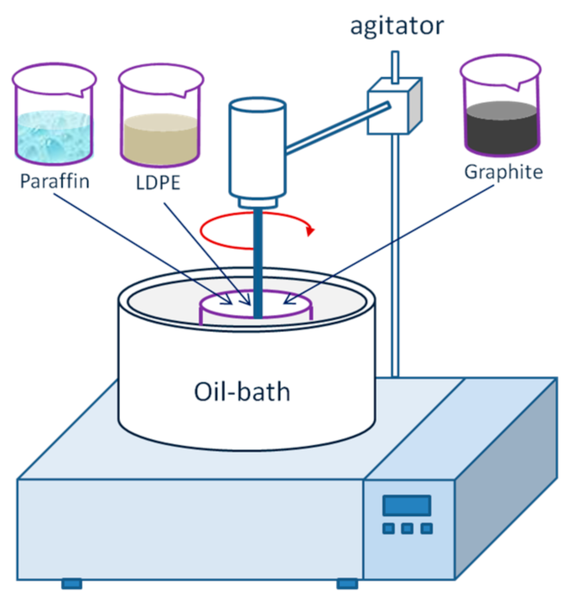
2.2.1. Preparation of SSPCM

Focusing on the purpose of improving thermal conductivity of SSPCM, an appropriate amount of graphite was added into the SSPCM mixture according to the reported method [24]. SSPCM was prepared by means of the hot melt mixing. For preparing SSPCM, LDPE, paraffin and graphite were weighed, respectively, and their mass proportion was fixed at 4:6:0.4. The mixture was heated to 150 °C in a constant temperature oil bath while mechanically stirred for 30 min at this temperature. The schematic of preparation apparatus is shown in Figure 3. Next, the molten mixture was solidified naturally at room temperature. The solidified mixture was broken into particles smaller than 2.5 mm in size using a crusher. Figure 4 is representative of the particles that were obtained.
A laser confocal scanning microscope (LCSM, Type: LEXT OLS4000) was employed to observe the structure of the SSPCM and SCTESM. It can be observed that the LDPE formed a porous network after cooling at room temperature, which encapsulated paraffin in a multilevel, dispersed structure to obtain the SSPCM (as shown in Figure 5). Flake graphite added during the preparation of SSPCM can be observed to be distributed evenly in the SSPCM matrix (shown in Figure 6).

2.2.2. Preparation of SCTESM

SCTESM was produced by incorporating SSPCM into the SAC mortar. The mixing proportions of the SCTESM specimens are shown in Table 1.
For all SCTESM specimens in Table 1, the water–cement ratio was 0.45 and the sand–cement ratio was 1.0. The mass fraction of SSPCM (with respect to cement) in SCTESM specimens were 0%, 20%, 30%, 40%, and 50%. The superplasticizer was added to acquire similar workability of the specimens with the superplasticizer–cement ratio varying from 0.06% to 0.80%. SCTESM specimens were prepared through a three-step procedure. Firstly, cement, standard sand, and SSPCM were weighed according to the mixing proportions in Table 1 for dry mixing. Secondly, superplasticizer and water were weighed and put into dry mixture, and the mixture was mixed for 3 min. Finally, the fresh SCTESM slurry was cast in molds. Specimens were cured under the conditions of temperature 20 ± 1 °C and relative humidity higher than 90%. The specimens included prisms, panels, and two sizes of cylinders. The prismatic specimens (40 × 40 × 160 mm) were used to measure strength and volume stability. The panel specimens (300 × 300 × 30 mm) were used to test thermoregulating performance. The thermal conductivity testing was carried out using the cylindrical specimens with a diameter of 30 mm and a thickness of 13 mm. The cylindrical specimens with a diameter of 30 mm and a thickness of 25 mm were prepared to carry out the infrared thermography for investigating the latent heat storage characteristics. According to the research objectives, the specimens with different SSPCM dosage in Table 1 were selected for testing and investigating.

2.3. Test Methods

2.3.1. Latent Heat

The phase transition temperature and latent heat of paraffin, SSPCM and SCTESM were determined using a differential scanning calorimeter (DSC) (type: NETZSCH 200F3). The accuracy of the DSC is ±10 μW, and the temperature accuracy is ±0.1 °C. The determination was conducted at a heating and cooling rate of 5 °C/min in a nitrogen atmosphere with a temperature range of −30–50 °C.

2.3.2. Thermal Stability

Thermogravimetric analyzer (TGA, type: STA449F3) with accuracy of ±0.1 μg was employed to measure the thermal stability of specimens. In the process of testing, the heating rate was 10 °C/min under an argon gas atmosphere from room temperature to 500 °C.

2.3.3. Thermal Conductivity

A thermal conductivity meter (type: DZDRS) was employed to determinate the thermal conductivity of several kinds of samples which error is less than 5%. Before testing, specimens cured for 28 days according to standard were dried to a constant weight in a 50 °C oven. Two identical cylindrical specimens with a diameter of 30 mm and a thickness of 13 mm were required and polished at the top and bottom surfaces for thermal conductivity determination. During the test, two identical specimens were stacked together, and the thermal conductivity meter test probe was placed in the middle. The surfaces of the two identical specimens that were in contact with each other were coated with thermal conductive silicone to reduce thermal contact resistance between the test probe and the specimens. The thermal conductivity of each SCTESM specimen with different SSPCM mass fractions was measured three times, and the average value was taken as the determined value. When the thermal conductivity was tested, the ambient temperature was maintained at 25 °C.

2.3.4. Volume Change

A vibrating wire strain gauge (type: xhx-21) with accuracy of ±0.1 με was utilized to investigate the volume change of SCM (i.e. sulphoaluminate cement mortar without SSPCM) and SCTESM-C5. The initial length of specimens was recorded after they were cured in the standard curing room for 12 h. Then, the specimens were cured in a room with relativity humidity and temperature of 40 ± 5% and 23 ± 2 °C, respectively, and the change in length of specimens was recorded continuously for 40 days. Six prismatic specimens were used for the volume change measurement and the average value of volume change was determined to investigate the volume change. The effect of SSPCM content on the volume stability of specimens was investigated by the determination of the change in length of specimens, as shown in Figure 7.

2.3.5. Latent Heat Storage Performance

Latent heat storage performance of SCTESM specimens with different dosages of SSPCM was measured by an infrared thermal imager (FLIR T420) system with accuracy of 0.1 °C. Three cylindrical specimens of SCM, SCTESM-C3, and SCTESM-C5 with a diameter of 30 mm and a thickness of 25 mm were prepared to investigate the latent heat storage performance. A similar test method was used previously [25,26]. Before infrared thermography was carried out, the specimens were dried to constant weight and then cooled at 0 °C for 24 h. Specimens were subsequently placed onto a heating device with 50 °C constant temperature. The bottom surfaces of the specimens were coated with a thermal conductive silicone to reduce the contact thermal resistance between the heating device and the test specimens. The microscope lens of the infrared thermal imager was installed at 25 cm above the upper surface of the specimen. The infrared thermal images were recorded once a minute for 15 min.

2.3.6. Thermoregulating Performance

The thermoregulating performance of SCTESM refers to the ability to regulate indoor air temperature and was evaluated using a self-made experimental device. The experimental device is shown in Figure 8, and it has been described in detail in our previous research [23]. The ability of SCTESM to regulate the indoor temperature was evaluated by thermocouples with an accuracy of 0.1 °C. Considering thermoregulating applications, a greater thermal energy storage capacity and a higher rate of energy charging/discharging of SCTESM can result in a smaller fluctuation range of the indoor air temperature.
After curing for 28 days and then drying at 50 °C to a constant weight, three panel specimens (300 × 300 × 30 mm) with SSPCM mass fraction of 0%, 30%, and 50% were tested, respectively. The test chamber was a cube box model composed of six 300 × 300 × 30 mm expanded polystyrene (EPS) panels. In the chamber, a SCTESM test panel was placed on the bottom and a 25 W iodine-tungsten filament lamp was fixed at the top center as a heat source during heating. The thermocouples were fixed at the center of the chamber and at the interior surface of the specimen panel. During the test, the thermocouples were covered by foil to avoid interference of direct light to temperature measurement.
The chamber with specimen and thermocouples installed was cooled in a cold room at −15 °C for 150 min. Then, the lamp inside the test chamber was turned on to heat the air temperature for 180 min. The test process consisted of two stages of cooling and heating. The air temperature in the chamber and the inner surface temperature of the test panel were recorded per 5 min by thermocouples. Depending on the collected temperature data, the temperature falling and rising curve was acquired to analyze the thermoregulating performance of SCTESM.

2.3.7. Mechanical Properties

To determine the mechanical strength of SCTESM at the curing age of 1, 3, 7, and 28 days, three prismatic specimens (40 × 40 × 160 mm) were needed for flexural strength determination and six specimens (about 40 × 40 × 80 mm) for compressive strength determination. The instrument accuracy, loading rate, and operation method of the mechanical strength test were carried out complying with the standard GB/T 17,671 (Chinese National Standard).

3. Results and Discussion

3.1. Latent Heat of Paraffin, SSPCM, and SCTESM

The PCM dosage has a great influence on the latent heat performance of SCTESM. SCTESM-C5 with the largest SSPCM dosage was selected to test latent heat and phase transition temperature. The paraffin, SSPCM, and SCM (without paraffin) were tested for the comparative analysis. The DSC curves of test specimens are presented in Figure 9.
Figure 9a presents that, in the melting process, the latent heat, initial phase change temperature, and peak phase change temperature of paraffin are 173.0 J/g, 18.5 °C, and 24.1 °C, while in the freezing process, those are 178.4 J/g, 19.9 °C, 15.6 °C, respectively. As for SSPCM, it is shown in Figure 9a that, in the melting process, the latent heat, initial melting temperature, and peak melting temperature are 99.99 J/g, 17.7 °C, and 25.5 °C, and in the freezing process, the latent heat, initial freezing temperature, and peak freezing temperature are 98.49 J/g, 19.8 °C, and 17.2 °C, respectively. According to the results, it can be calculated that the paraffin encapsulation ratio in SSPCM is 56.0% which is slightly higher than the previously reported 52.2% for microencapsulated paraffin encapsulation ratio [24].
Figure 9b shows the DSC curves of the specimens SCM and SCTESM-C5. The initial phase change temperatures of SCTESM-C5 are 15.1 and 19.4 °C for the melting process and the freezing processes, respectively. Moreover, the peak temperature and latent heat of SCTESM-C5 are 21.2 °C and 12.8 J/g for the melting process, and 17.5 °C and 11.8 J/g for the freezing process. Furthermore, it can be observed from Figure 9b that the SCM, in the absence of PCM, does not show the endothermic peak and exothermic peaks during its heating and cooling process.

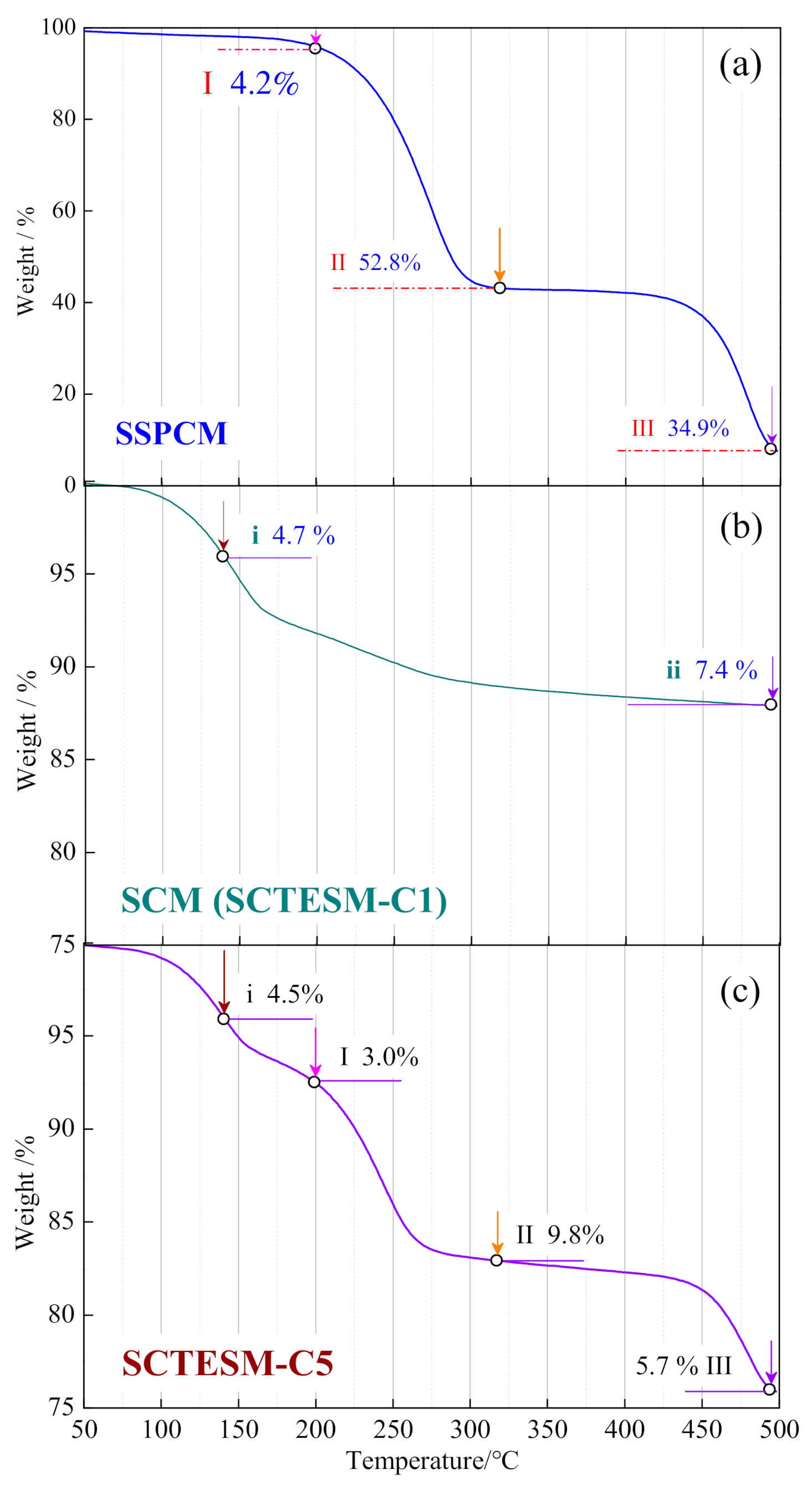
3.2. Thermal Stability of SSPCM, SCM, and SCTESM

Due to the thermal stability of SCTESM, that is, its decomposition temperature mainly depends on the types of its components rather than the content of each component, only SCTESM-C5, SSPCM, and SCM were used in the TGA test. Through the test and comparative analysis of the two specimens, the thermal stability of SCTESM can be clarified. TGA measurements were performed from 50 to 500 °C with a temperature rising rate of 30 °C/min. The TGA of SCM and SSPCM were carried out in the same conditions in order to understand the cause of the degradation of SCTESM in different temperature ranges, since SCTESM was composed of SAC mortar (SCM) and SSPCM. Figure 10 illustrates the TGA curves of SSPCM, SCM, and SCTESM-C5.
In the TGA curve of the SSPCM specimen in Figure 10a, three weight loss stages are observed. The first weight loss stage occurs between 50 and 200 °C, in this stage, 4.2% weight is lost from SSPCM owing to the evaporation of free-water [24,27]. The second weight loss stage of SSPCM occurs from 200 to 320 °C, where 52.8% weight is lost due to the decomposition of the paraffin [28,29]. The third weight loss stage begins at 412 °C and ends at 495 °C, where the weight loss of SSPCM is 34.9%, mainly due to the decomposition of LDPE [27]. From Figure 10b, it can be found that the weight loss of SCM occurs in two stages. In the first stage, the specimen loses 4.7% weight, which is attributed to the evaporation of free-water [24]. In the second stage, a 7.4% weight loss is resulted by the evaporation of bound water of ettringite and the dehydration of Al (OH)3 gels and other hydration products [30].
Based on the TGA curves of the SSPCM and SCM samples, it can be deduced that the degradation of SCTESM is caused by the degradation of the individual components of SSPCM and SCM. The TGA curves in Figure 10c demonstrate that the paraffin and cement hydration products do not show significant decomposition below 145 °C except a slight weight loss owing to evaporation of water. Therefore, it can be confirmed that the SCTESM has significant thermal stability under its ordinary working temperature in building sections [31].

3.3. Thermal Conductivity of SCTESM

The thermal conductivity is a key thermal property parameter for thermal energy storage applications of SCTESM. In order to ascertain the effect of SSPCM mass fraction on the thermal conductivity of SCTESM and construct a mathematical model, all SCTESM specimens with different SSPCM mass fraction were carried out to obtain the necessary measurement data. The influence of SSPCM dosage on the thermal conductivity of SCTESM is illustrated in Figure 11.
Figure 11 reveals that the thermal conductivity of the SCTESM decreases with the increase of the SSPCM mass fraction. When the mass fraction of SSPCM increases from 0 to 20, 30, 40, and 50 wt.%, the thermal conductivity of SCTESM decreases from 0.9324 to 0.8332, 0.7803, 0.6510, and 0.5755 W m−1 K−1, respectively. Compared to SCM, the thermal conductivity reduction percentages of SCTESM-C2, SCTESM-C3, SCTESM-C4, and SCTESM-C5 are 10.6%, 16.3%, 30.2%, and 38.3%, respectively. A significant linear relationship between the thermal conductivity of SCTESM and the SSPCM dosages is observed and is expressed as following:
y = 0.0073 x + 0.9574 ,
where y is the thermal conductivity of SCTESM, W m−1 K−1, and x represents the mass fraction of SSPCM with respect to cement, %. The R 2 value of this relationship is 0.9457. Therefore, the thermal conductivities of SCTESMs can be estimated using this empirical formula.
It is known from the literature [32] that paraffin has a low thermal conductivity of 0.21 W m−1 K−1 in its solid state and 0.15 W m−1 K−1 in its liquid state. From the thermal conductivity determination result of SCM (without SSPCM), it can be found that its thermal conductivity of 0.9324 W m−1 K−1 is higher than that of paraffin. For this reason, a higher SSPCM dosage results in decreasing thermal conductivity. Similar results by Cui et al. [24] and Hunger et al. [33] showed a negative correlation between the content of paraffin and the thermal conductivity of cement-based energy storage materials.

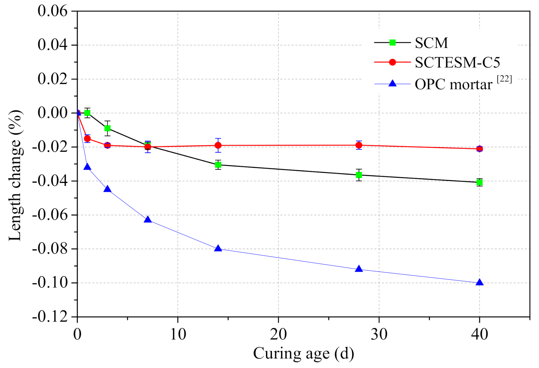
3.4. Volume Stability of SCTESM

The presence and content of paraffin can affect the volume stability of SCTESM. In order to explore the effect of paraffin on the volume stability of SCTESM, SCTESM-C5, and SCM were selected for determination and comparative analysis. The mixing proportions of SCTESM specimens (Table 1) show that SCTESM-C5 has the largest amount of SSPCM and SCM does not contain SSPCM. The volume stability of SCTESM-C5 and SCM is shown in Figure 12.
Figure 12 illustrates that the volume shrinkage of SCTESM-C5 occurs only in the first few days and then rapidly develops into a steady state. However, the volume shrinkage of SCM occurs continuously throughout the 40-day testing period. In comparison with SCM, the maximum volume shrinkage of SCTESM-C5 is reduced by 48.4%. The volume shrinkage comparison results in Figure 12 indicate that incorporation of SSPCM into cement mortar matrix is beneficial to reduce the volume shrinkage of SCTESM. After SSPCM incorporation, the relative content of the cement in the SCTESM will decrease, which leads to the decrease of volume shrinkage of SCTESM.
Furthermore, it is noteworthy that the volume shrinkage of SCM is far less than that of OPC mortar [22]. According to the report by Cui et al. [24], there is a significant gap between the PCM and OPC mortar matrix due to the volume shrinkage of OPC. However, in this study, the high volume stability of SAC mortar is beneficial for reducing the gaps between components. As shown in Figure 13, the interfacial transition zone between SSPCM and the cement matrix exhibits tight bonding characteristics, which can improve the heat transfer efficiency between the SSPCM and the matrix.

3.5. Latent Heat Storage Properties

The latent heat storage properties of SCTESM are mainly affected by SSPCM mass fraction. Therefore, in order to compare and verify the influence of SSPCM mass fraction on the latent heat storage properties of SCTESM, the SCM (without SSPCM), SCTESM-C3 (30% wt. SSPCM), and SCTESM-C5 (50% wt. SSPCM) were selected for infrared thermography investigation. The upper surface temperature of the test specimens was measured by infrared thermography and the average upper surface temperature was calculated. The measured upper surface temperatures and infrared thermography images of SCM, SCTESM-C3, and SCTESM-C5 are shown in Figure 14.
It is demonstrated in Figure 14 that compared with SCTESM-C3 and SCTESM-C5, the top surface temperature of the SCM sample rises faster. When heated for 3 min, the temperature increase rate of SCTESM-C3 and SCTESM-C5 starts to reduce and the temperature difference between the three samples begins to increase. The maximum temperature difference between SCM and SCTESM-C3 is 5.4 °C after 5 min and that between SCTESM-C3 and SCTESM-C5 is 5.5 °C after 9 min. Compared to the temperature of SCM, the maximum reduction temperature of SCTESM-C5 is 9.2 °C after heating for 9 min.
It can be deduced that the SSPCMs incorporated into SCTESM-C3 and SCTESM-C5 provide much higher latent heat storage density. The results indicate that the higher the SSPCM dosage in the cement mortar, the higher the thermal energy storage capacity and the stronger the ability to delay temperature changes. Results from similar investigations in the literature support this view [34,35].

3.6. Thermoregulating Performance of SCTESM

The measurement of thermal regulation performance aims to reflect the difference in the characteristics of SCTESM latent heat storage and sensible heat storage, as well as the difference thermal regulation performances of SCTESM with different SSPCM mass fractions. Therefore, for a comparative analysis of the thermal energy storage capacity and thermal energy storage/release efficiency, SCM, SCTESM-C3, and SCTESM-C5 were selected as the minimum and necessary samples for this measurement. The thermoregulating performance of SCTESMs was investigated by measuring the change of the air temperature in the chamber and the inner surface temperature of test panels. The temperatures were measured over a period of heating and cooling, and the results are presented in Figure 15.
The temperature curves in Figure 15 demonstrate that the air temperatures (dotted lines) in the test chamber decline nonlinearly during the 150 min cooling period and increase nonlinearly in the 180 min heating period. Moreover, a significant temperature difference between air and inner surface is demonstrated.
During the cooling process, it can be seen from Figure 15 that the values of the indoor air temperature are different for SCM, SCTESM-C3, and SCTESM-C5 panels. The air temperature and surface temperature all reach the lowest values at the completion of the 150 min cooling period. The lowest indoor air temperatures corresponding to SCTESM-C5 and SCTESM-C3 are 2.3 and 1.5 °C higher than that of SCM, respectively. Meanwhile, the lowest inner surface temperatures of SCTESM-C5 and SCTESM-C3 are 4.5 and 3.3 °C higher than that of SCM, respectively. For the heating period, the air temperature in the chamber and inner surface temperature variation curves are also presented in Figure 15. After the 180 min heating period, the inner surface temperature corresponding to the SCM panel is 1.1 °C higher than that of SSPCM-C5 and 1.6 °C higher than that of SSPCM-C3. Meanwhile, the indoor air temperature corresponding to the SCM panel is 2.0 °C higher than that of SSPCM-C3 and 3.9 °C higher than that of SSPCM-C5. From the whole indoor air temperature fluctuation process, it can be found that SSPCM-C5 has the lowest the temperature fluctuation, which is 2.7 °C lower than SSPCM-C3 and 6.2 °C lower than SCM.
Furthermore, it is worth noting that for all specimens the rate of temperature change was obviously lower for inner surface temperature and lags behind indoor air temperature. This is a result of the thermal energy charging/discharging characteristics of SCTESM during heating and cooling. Besides, it should be noted that thermoregulating performance of SCTESM is closely related to SSPCM content. These results demonstrate a promising application of SCTESM in improving the quality of the indoor thermal environment and efficient energy utilization.

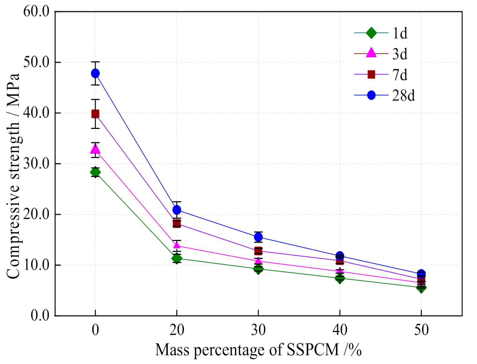
3.7. Mechanical Properties of SCTESM

In order to ascertain the effect of SSPCM mass fraction on the compressive strength of SCTESM and construct a mathematical model, all SCTESM specimens with different SSPCM mass fractions were tested. The mechanical strength of SCTESM specimens with different SSPCM dosages are shown in Figure 16 and Figure 17. The mass fractions of SSPCM in SCTESM specimens are 0%, 20%, 30%, 40%, and 50%, respectively.
It can be seen from Figure 16 and Figure 17 that the compressive strengths of SCM at 1, 3, 7, and 28 days curing age are 28.3, 32.7, 39.8, and 44.4 MPa, respectively. The flexural strengths of SCM at 1, 3, 7, and 28 days curing age are 6.1, 6.9, 7.8, and 9.3 MPa. The compressive strengths of SCM at 1, 3, and 7 days are 63.7%, 73.6%, and 89.6% of that at 28 days curing age. The flexural strengths of SCM at 1, 3, and 7 days curing age are 65.6%, 74.2%, and 83.9% of that at 28 days curing age, respectively. Furthermore, it is found that SCTESMs has high early strength. Even though the mass percentage of SSPCM is 50% with respect to cement, the compressive strength at 1, 3, and 7 days curing age reaches 67.5%, 78.3%, and 86.7% of that at 28 days curing age.
However, it is noteworthy that the incorporation of SSPCM greatly lowers the mechanical strength of SCTESM. The measurement results in Figure 16 and Figure 17 reveal that in comparison with SCM, the 28-day compressive strength and flexural strength of SCTESM with 50% SSPCM reduce by 70.7% and 73.1%, respectively. SSPCM particles prepared with paraffin and LDPE perform more like voids rather than fine aggregates in SCTESM in this study. To assess the behavior of SSPCM in SCTESM during compression, based on the literature [32], a new modified Bolomey equation is proposed to predicate the compressive strength of SCTESM at 28 days:
f S C T E S M 28 = K B × σ S C M 28 C W + W S S P C M 0.5 ,
where fSCTESM28 refers to the compressive strength of SCTESM at 28 days age; KB is a constant ranging from 0.35 to 0.65, the mean value of 0.50 is chosen; σSCM28 is the compressive strength of SCM at 28 days curing age and the experimental value of 44.4 MPa is chosen with error is 4.78%; W and C are the mass of water and cement; WSSPCM is the mass of water equal to the volume occupied by the SSPCM in the SCTESM (the apparent density of SSPCM is 0.86 g/cm3). Figure 18 shows the SCTESM compressive strength measurements at 28 days curing age versus model predicted values.
It can be seen from Figure 18 that the experimental values of SCTESM at 28 days are close to the model predicted values and it is deduced that SSPCM particles behavior can be considered as voids in SCTESM. Moreover, it is noteworthy that measurement values are less than the model predicted value and the difference increases slightly with increasing SSPCM dosage. This phenomenon may be associated with the increasing of SSPCM dosage that not only increases the void amount but also exacerbates the adverse effects on the structure of the matrix.

4. Conclusions

In this research, a LDPE/paraffin/graphite composite shape stabilized phase change materials (SSPCM) was prepared by the heated mixing method. This SSPCM was then incorporated into sulphoaluminate cement based thermal energy storage mortars (SCTESM). The thermophysical and mechanical characteristics of SCTESM with different dosage SSPCM were investigated. According to the experimental results, the following conclusions are drawn:
(1)
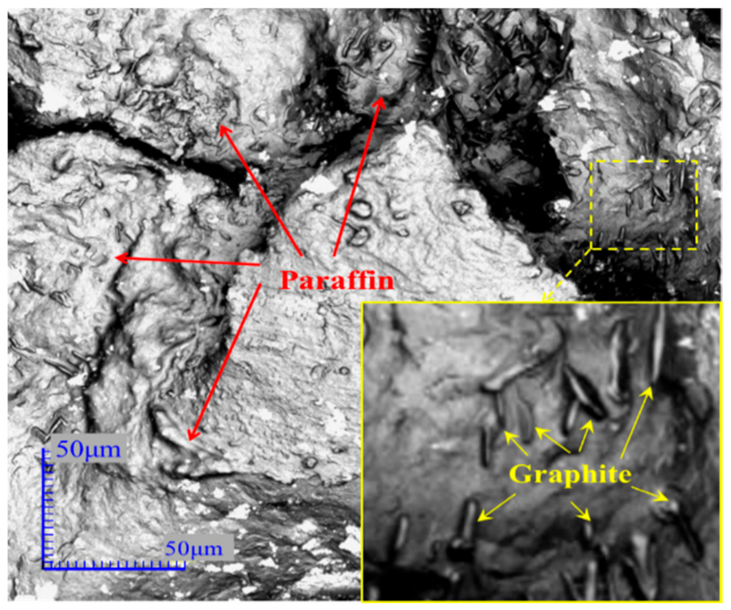
SSPCM composite has a peak melting temperature and latent heat of 25.5 °C and 99.99 J/g, respectively. LSCM test results show that paraffin can be well encapsulated into the multilayer space network formed by LDPE. A 50% mass fraction of SSPCM with respect to cement can be contained within the cement mortar, resulting in SCTESM with a peak melting temperature and a latent heat of 21.2 °C and 12.8 J/g, respectively.
(2)
Due to the negligible volume shrinkage of the sulphoaluminate cement mortar, the SCTESM has excellent volume stability and SSPCM particles can be tightly integrated with the mortar matrix. The volume shrinkage of SCTESM decreases with increasing SSPCM mass fraction. Compared with SCM, the maximum volume shrinkage of SCTESM-C5 is reduced by 48.4%. TGA results suggest that SCTESM has excellent thermal stability below 145 °C.
(3)
Since the paraffin has the lower thermal conductivity, larger SSPCM dosages resulted in more significant decreases in thermal conductivity. The thermal conductivity of SCTESM decreases from 0.9324 to 0.5755 W m−1 K−1 with the SSPCM mass fraction increasing from 0 to 50 wt.%. A strong linear relationship between thermal conductivity and SSPCM dosages is proposed.
(4)
SCTESM has a significant effect of smoothing room temperature fluctuations, and the temperature adjustment ability of SCTESM is positively correlated with its SSPCM content. Compared with SCM, SSPCM-C5 reduces indoor air temperature fluctuation range by 6.2 °C. These results indicate that SCTESM has promising applications in improving the indoor temperature stability.
(5)
SCTESM has the properties of high early strength, such that the compressive strengths of SCTESM-C5 at 1, 3, and 7 days are 67.5%, 78.3%, and 86.7% of that of 28-day compressive strength, respectively. However, as the dosage of SSPCM increases, the compressive and flexural strength of SCTESM decreases. This phenomenon was explained with a new modified Bolomey equation that demonstrated that SSPCM particles behave like voids in SCTESM.

Author Contributions

Conceptualization, G.S. and X.C.; methodology, Y.C.; software, X.D.; validation, G.S., X.C. and L.Z.; formal analysis, X.C.; investigation, Y.C., X.D.; data curation, Y.C.; writing—original draft preparation, X.C.; writing—review and editing, G.S. and Y.Z. (Yangkai Zhang); supervision, G.S.; project administration, Y.Z. (Yiyun Zhu); funding acquisition, G.S. All authors have read and agreed to the published version of the manuscript.

Funding

This research was financially supported by the National Nature Science Foundation of China (NSFC, grant number 51678482) and the Department of Science and Technology of Shaanxi Province (DSTSN, grant number 2020ZDLNY06-05). The APC was funded by 51678482 and 2020ZDLNY06-05.

Acknowledgments

This work is based on the research financially supported wholly or in part by the National Nature Science Foundation of China (grant number 51678482) and the Department of Science and Technology of Shaanxi Province (grant number 2020ZDLNY06-05). The opinions, findings, and conclusions or recommendations expressed are those of the author(s) alone, and the NSFC and DSTSN accept no liability whatsoever in this regard.

Conflicts of Interest

The authors declare no conflict of interest.

References

  1. Lotfabadi, P.; Alibaba, H.Z.; Arfaei, A. Sustainability; as a combination of parametric patterns and bionic strategies. Renew. Sustain. Energy Rev. 2016, 57, 1337–1346. [Google Scholar] [CrossRef]
  2. Shaikh, P.H.; Nor, N.B.M.; Nallagownden, P.; Elamvazuthi, I. Intelligent multi-objective optimization for building energy and comfort management. J. King Saud Univ.-Eng. Sci. 2018, 30, 195–204. [Google Scholar] [CrossRef] [Green Version]
  3. Zhu, N.; Hu, N.; Hu, P.; Lei, F.; Li, S. Experiment study on thermal performance of building integrated with double layers shape-stabilized phase change material wallboard. Energy 2019, 167, 1164–1180. [Google Scholar] [CrossRef]
  4. Li, M.; Wu, Z.; Kao, H.; Tan, J. Experimental investigation of preparation and thermal performances of paraffin/bentonite composite phase change material. Energy Convers. Manag. 2011, 52, 3275–3281. [Google Scholar] [CrossRef]
  5. Feliński, P.; Sekret, R. Experimental study of evacuated tube collector/storage system containing paraffin as a PCM. Energy 2016, 114, 1063–1072. [Google Scholar] [CrossRef]
  6. Zhou, X.; Yu, Q.; Zhang, S.; Zhang, C.; Feng, J. Porous silica matrices infiltrated with PCM for thermal protection purposes. Ceram. Int. 2013, 39, 5247–5253. [Google Scholar] [CrossRef]
  7. Memon, S.A.; Cui, H.; Lo, T.Y.; Li, Q. Development of structural–functional integrated concrete with macro-encapsulated PCM for thermal energy storage. Appl. Energy 2015, 150, 245–257. [Google Scholar] [CrossRef]
  8. Qian, T.; Li, J. Octadecane/C-decorated diatomite composite phase change material with enhanced thermal conductivity as aggregate for developing structural–functional integrated cement for thermal energy storage. Energy 2018, 142, 234–249. [Google Scholar] [CrossRef]
  9. Jamekhorshid, A.; Sadrameli, S.M.; Farid, M. A review of microencapsulation methods of phase change materials (PCMs) as a thermal energy storage (TES) medium. Renew. Sustain. Energy Rev. 2014, 31, 531–542. [Google Scholar] [CrossRef]
  10. Sánchez-Silva, L.; Rodriguez, J.F.; Romero, A.; Borreguero, A.; Carmona, M.; Sánchez, P. Microencapsulation of PCMs with a styrene-methyl methacrylate copolymer shell by suspension-like polymerisation. Chem. Eng. J. 2010, 157, 7. [Google Scholar] [CrossRef]
  11. Zhang, Y.P.; Lin, K.P.; Yang, R.; Di, H.F.; Jiang, Y. Preparation, thermal performance and application of shape-stabilized PCM in energy efficient buildings. Energy Build. 2006, 38, 1262–1269. [Google Scholar] [CrossRef]
  12. Tang, Y.; Su, D.; Huang, X.; Alva, G.; Liu, L.; Fang, G. Synthesis and thermal properties of the MA/HDPE composites with nano-additives as form-stable PCM with improved thermal conductivity. Appl. Energy 2016, 180, 116–129. [Google Scholar] [CrossRef]
  13. Lo, K.-W.; Lin, K.-L.; Cheng, T.-W.; Chang, Y.-M.; Lan, J.-Y. Effect of nano-SiO2 on the alkali-activated characteristics of spent catalyst metakaolin-based geopolymers. Constr. Build. Mater. 2017, 143, 455–463. [Google Scholar] [CrossRef]
  14. Cui, H.; Tang, W.; Qin, Q.; Xing, F.; Liao, W.; Wen, H. Development of structural-functional integrated energy storage concrete with innovative macro-encapsulated PCM by hollow steel ball. Appl. Energy 2017, 185, 107–118. [Google Scholar] [CrossRef]
  15. Turner, L.K.; Collins, F.G. Carbon dioxide equivalent (CO2-e) emissions: A comparison between geopolymer and OPC cement concrete. Constr. Build. Mater. 2013, 43, 125–130. [Google Scholar] [CrossRef]
  16. Ali, M.B.; Saidur, R.; Hossain, M.S. A review on emission analysis in cement industries. Renew. Sustain. Energy Rev. 2011, 15, 2252–2261. [Google Scholar] [CrossRef]
  17. Li, G.; Zhang, J.; Song, Z.; Shi, C.; Zhang, A. Improvement of workability and early strength of calcium sulphoaluminate cement at various temperature by chemical admixtures. Constr. Build. Mater. 2018, 160, 427–439. [Google Scholar] [CrossRef]
  18. Zhang, G.; Li, G.; Li, Y. Effects of superplasticizers and retarders on the fluidity and strength of sulphoaluminate cement. Constr. Build. Mater. 2016, 126, 44–54. [Google Scholar] [CrossRef]
  19. Winnefeld, F.; Lothenbach, B. Hydration of calcium sulfoaluminate cements—Experimental findings and thermodynamic modelling. Cem. Concr. Res. 2010, 40, 1239–1247. [Google Scholar] [CrossRef]
  20. Sun, K.; Zhou, X.; Gong, C.; Ding, Y.; Lu, L. Influence of paste thickness on coated aggregates on properties of high-density sulphoaluminate cement concrete. Constr. Build. Mater. 2016, 115, 125–131. [Google Scholar] [CrossRef] [Green Version]
  21. Wang, D.; Liu, Q.G.Y.; Wang, Y.; Chen, Y.; Liu, Y.; Liu, J. Experimental study on heating characteristics and parameter optimization of transpired solar collectors. Appl. Energy 2019, 238, 13. [Google Scholar] [CrossRef]
  22. Xu, B.; Li, Z. Paraffin/diatomite composite phase change material incorporated cement-based composite for thermal energy storage. Appl. Energy 2013, 105, 229–237. [Google Scholar] [CrossRef]
  23. Sang, G.; Cao, Y.; Fan, M.; Lu, G.; Zhu, Y.; Zhao, Q.; Cui, X. Development of a novel sulphoalumitate cement-based composite combing fine steel fibers and phase change materials for thermal energy storage. Energy Build. 2019, 183, 75–85. [Google Scholar] [CrossRef]
  24. Cui, H.; Liao, W.; Mi, X.; Lo, T.Y.; Chen, D. Study on functional and mechanical properties of cement mortar with graphite-modified microencapsulated phase-change materials. Energy Build. 2015, 105, 273–284. [Google Scholar] [CrossRef]
  25. Cui, H.; Feng, T.; Yang, H.; Bao, X.; Tang, W.; Fu, J. Experimental study of carbon fiber reinforced alkali-activated slag composites with micro-encapsulated PCM for energy storage. Constr. Build. Mater. 2018, 161, 442–451. [Google Scholar] [CrossRef]
  26. Zhang, H.; Xing, F.; Cui, H.-Z.; Chen, D.-Z.; Ouyang, X.; Xu, S.-Z.; Wang, J.-X.; Huang, Y.-T.; Zuo, J.-D.; Tang, J.-N. A novel phase-change cement composite for thermal energy storage: Fabrication, thermal and mechanical properties. Appl. Energy 2016, 170, 130–139. [Google Scholar] [CrossRef]
  27. Yin, D.; Ma, L.; Liu, J.; Zhang, Q. Pickering emulsion: A novel template for microencapsulated phase change materials with polymer–silica hybrid shell. Energy 2014, 64, 575–581. [Google Scholar] [CrossRef]
  28. Dsilva Winfred Rufuss, D.; Iniyan, S.; Suganthi, L.; Davies, P.A. Low mass fraction impregnation with graphene oxide (GO) enhances thermo-physical properties of paraffin for heat storage applications. Thermochim. Acta 2017, 655, 226–233. [Google Scholar] [CrossRef] [Green Version]
  29. Memon, S.A.; Liao, W.; Yang, S.; Cui, H.; Shah, S.F.A. Development of Composite PCMs by Incorporation of Paraffin into Various Building Materials. Materials 2015, 8, 499–518. [Google Scholar] [CrossRef]
  30. Wang, P.L.N.; Xu, L.; Zhang, G. Hydration Characteristics and Strength Development of Sulphoaluminate Cement Cured at Low Temperature. J. Chin. Ceram. Soc. 2017, 45, 7. [Google Scholar]
  31. Oya, T.; Nomura, T.; Tsubota, M.; Okinaka, N.; Akiyama, T. Thermal conductivity enhancement of erythritol as PCM by using graphite and nickel particles. Appl. Therm. Eng. 2013, 61, 825–828. [Google Scholar] [CrossRef]
  32. Lecompte, T.; Le Bideau, P.; Glouannec, P.; Nörtershäuser, D.; Le Masson, S. Mechanical and thermo-physical behaviour of concretes and mortars containing phase change material. Energy Build. 2015, 94, 52–60. [Google Scholar] [CrossRef]
  33. Hunger, M.; Entrop, A.G.; Mandilaras, I.; Brouwers, H.J.H.; Founti, M. The behavior of self-compacting concrete containing micro-encapsulated Phase Change Materials. Cem. Concr. Compos. 2009, 31, 731–743. [Google Scholar] [CrossRef]
  34. Qiu, X.; Song, G.; Chu, X.; Li, X.; Tang, G. Microencapsulated n-alkane with p(n-butyl methacrylate-co-methacrylic acid) shell as phase change materials for thermal energy storage. Sol. Energy 2013, 91, 212–220. [Google Scholar] [CrossRef]
  35. Amaral, C.; Vicente, R.; Marques, P.A.A.P.; Barros-Timmons, A. Phase change materials and carbon nanostructures for thermal energy storage: A literature review. Renew. Sustain. Energy Rev. 2017, 79, 1212–1228. [Google Scholar] [CrossRef]
Figure 1. Low density polyethylene (LDPE).
Energies 13 05024 g001
Figure 2. SEM image of flake graphite.
Energies 13 05024 g002
Figure 3. Schematic of shape-stabilized phase change material (SSPCM) preparation.
Energies 13 05024 g003
Figure 4. SSPCM particles.
Energies 13 05024 g004
Figure 5. LSCM image of SSPCM network structure.
Energies 13 05024 g005
Figure 6. Laser confocal scanning microscope (LSCM) image of graphite distributed in SSPCM.
Energies 13 05024 g006
Figure 7. Device of length change test system.
Energies 13 05024 g007
Figure 8. Schematic of the experimental device: (a) overall schematic, (b) cross-sectional view.
Energies 13 05024 g008
Figure 9. Differential scanning calorimeter (DSC) curves: (a) paraffin and SSPCM; (b) SCTESM-C5 and SCM.
Energies 13 05024 g009
Figure 10. Thermogravimetric analysis curves: (a) SSPCM; (b) SCM; (c) SCTESM.
Energies 13 05024 g010
Figure 11. Thermal conductivity change of SCTESM with different dosages of SSPCM.
Energies 13 05024 g011
Figure 12. Comparison of volume shrinkage between SCM and SCTESM-C5.
Energies 13 05024 g012
Figure 13. LSCM image of interfacial transition zone of SCTESM.
Energies 13 05024 g013
Figure 14. Upper surface temperature and infrared thermography images.
Energies 13 05024 g014
Figure 15. Thermoregulating performance of SCETSM.
Energies 13 05024 g015
Figure 16. Compressive strength of SCTESM.
Energies 13 05024 g016
Figure 17. Flexural strength of SCTESM.
Energies 13 05024 g017
Figure 18. Compressive strength measurements versus model predicted values.
Energies 13 05024 g018
Table 1. Mixing proportion of sulphoaluminate cement-based thermal energy storage material (SCTESM).
GroupCement/gSand/gSSPCM/gSSPCM/wt%Water/gSuperplasticizer/g
SCM80080000360.00.48
SCTESM-C270070014020315.00.63
SCTESM-C365065019530292.51.36
SCTESM-C460060024040270.01.80
SCTESM-C555055027550247.54.40

