Article

Research on Synchronverter-Based Regenerative Braking Energy Feedback System of Urban Rail Transit

1
Key Laboratory of Magnetic Suspension Technology and Maglev Vehicle, Ministry of Education, School of Electrical Engineering, Southwest Jiaotong University, Chengdu 611756, China
2
China Railway Eryuan Engineering Group Co., Ltd. (CREEC), Chengdu 610031, China
3
The 13th Research Institute of China Electronic Technology Group Corporation, Shijiazhuang 050051, China
4
Center for Research on Microgrids (CROM), Department of Energy Technology, Aalborg University, 9220 Aalborg, Denmark
*
Author to whom correspondence should be addressed.
Energies 2020, 13(17), 4418; https://doi.org/10.3390/en13174418
Submission received: 26 July 2020 / Revised: 20 August 2020 / Accepted: 24 August 2020 / Published: 26 August 2020
(This article belongs to the Special Issue Microgrids 2020)

Abstract

:
Generally running with frequent braking over short distances, the urban rail transit train generates great quantities of regenerative braking energy (RBE). The RBE feedback system can effectively recycle RBE and give it back to the AC grid. However, the lack of damp and inertia of generators makes conventional PWM RBE feedback system more sensitive to power fluctuations. To address this issue, a synchronverter-based RBE feedback system of urban rail transit is designed in this paper. First, the structure of the feedback system is presented. Then, the synchronverter-based control strategy with greater flexibility and higher stability is fully discussed. Furthermore, the parameter design of the system is analyzed in detail. Finally, simulation results and experimental results are provided to show the good dynamic performance of the system. Using this synchronverter-based approach, the system supplies traction power to the traction network when the train accelerates and gives the RBE back to the AC grid when the train brakes, in light of the variation of the DC bus voltage. Moreover, the system can be self-synchronized with the AC grid and make corresponding power management on the basis of changes in the voltage amplitude as well as the frequency of the grid. In this sense, the RBE feedback system becomes more flexible, effective and robust.

Graphical Abstract

1. Introduction

Urban rail transit tends to be more efficient, flexible and energy saving. In light of the trend, subways have gradually become the mainstream in urban rail transit [1,2,3]. Subways generally run with frequent braking over short distances, thus can generate a large amount of regenerative braking energy (RBE), nearly 30–55% of the traction power [4,5]. A fraction of this part of energy can be absorbed by adjacent trains, while most of it will be left and consequently increase the DC bus voltage, which greatly disturbs the operation of the trains [6,7,8,9,10,11].
To cope with the problem, resistors are set in traction substations to consume RBE and accordingly suppress the increase of the DC bus voltage. Nevertheless, in this way, RBE is simply dissipated into the air in the form of heat, thus needs to consume extra energy to supply the temperature control equipment to cool the air, which is contrary to the demand of energy conservation. In addition, the in-station resistors cabinet needs to be placed separately, which increases the difficulty of site configuration [12]. However, if RBE could be recycled, it would not only supply for auxiliary equipment in the metro station but also feed the AC grid for reuse. In this sense, many RBE recycle approaches are developed to recycle the regenerative braking energy.
In general, the energy recycle approaches can be divided into energy storage methods and inverter feedback methods, according to the direction of the energy transmission. The former can quickly stabilize the DC bus voltage by setting energy storage equipment on the DC side to absorb RBE, such as super capacitors and flywheels, which can also suppress fluctuations of line voltage and optimize the energy cost. However, there are some drawbacks that limit the application of these energy storage methods. For instance, because of its bulky volume and insufficient capacity, existing supercapacitor equipment is not suitable to operate in a small area or for a long time. Moreover, flywheel storage equipment has not been applied in force due to its low energy density and high self-discharge rate. Both are limited by installation constraints as well as interoperability issues [13,14].
Another possibility to recycle RBE is to feedback RBE to the AC grid for reuse. When the train brakes and the DC bus voltage exceeds the threshold value, RBE of the train obtained from the traction power network is fed back to the 35-kV AC grid through the high-power three-phase PWM inverter. The droop control method is generally applied in this approach to avoid circulating currents among converters and communication between units. In this way, stable frequency and voltage of the system can be obtained by active power–frequency (P-f) droop control and reactive power–voltage (Q-V) droop control, simulating the primary droop characteristic of the motor. However, when the conventional droop control is applied to nonlinear loads system, harmonic problems and imbalance between the active power and reactive power are inevitable [15]. Moreover, the load-dependent frequency deviation problem also affects its dynamic performance. For instance, at the moment of grid-connection, this deviation will result in a loss of synchronization.
The virtual synchronous generator is developed to cope with the problem. This concept, first proposed by the Vertical Sync (VSYNC) project in Europe, adds the virtual inertia and damping to the conventional droop control and shows a better dynamic performance. Significant efforts have been done to develop the virtual synchronous generator. The existing virtual synchronous generators can be divided into current types and voltage types. At present, two current control schemes have been proposed: Virtual Synchronous Generator (VSG) proposed by The University of Leuven in Belgium and Virtual Synchronous Machine (VISMA) proposed by The Technical University of Lauxtal in Germany [16]. VSG, composed of a three-phase half-bridge inverter, a LCL filter and an ideal DC voltage source for energy storage, effectively improves the system frequency stability. Nevertheless, the simulation degree of excitation regulation mechanism of the synchronous generator is insufficient, leaving a gap between the algorithm and the principle of practical synchronous generator. VISMA indirectly constructs the synchronous generator model by directly controlling the inductance current of the AC side filter, thus simulating the characteristics of primary frequency modulation and primary voltage regulation [17]. However, the control accuracy of VISMA is easily affected by filter inductances. There are mainly two schemes for voltage-controlled virtual synchronous generator technology, the virtual inertial frequency control proposed by Iravani [18] and the synchronverter proposed by Zhong [19,20]. By using the virtual inertial frequency control, the inverter has the same moment of inertia and primary frequency modulation characteristics as the conventional synchronous generator. However, the simulation degree is insufficient. The synchronverter, the closest to the operation mechanism of the practical synchronous generator, does not need additional synchronization units, thus can synchronize with the grid smoothly. The synchronverter has been widely used in wind power generation, solar power generation, static reactive power compensation, motor speed regulation and other aspects [21,22,23,24]. However, the dynamic performance of the synchronverter is greatly affected by control parameters. Only a few works give a whole parameter design method of the overall control.
In this paper, a synchronverter-based RBE feedback system of urban rail transit is designed to supply traction power network with traction energy when the train accelerates and give RBE back to the AC grid when the train brakes. Moreover, the parameter design method of the overall synchronverter control is researched in detail. The rest of this paper is organized as follows. In Section 2, the structure of the RBE feedback system is presented, the control strategy of the system is fully discussed and the operation characteristics at different mode are analyzed. In Section 3, the system capacity and the controller parameters are designed in detail. In Section 4, the system performance is verified by simulations and experiments. The conclusion is presented in Section 5.

2. Overall Design of Synchronverter-Based Regenerative Braking Energy Feedback System

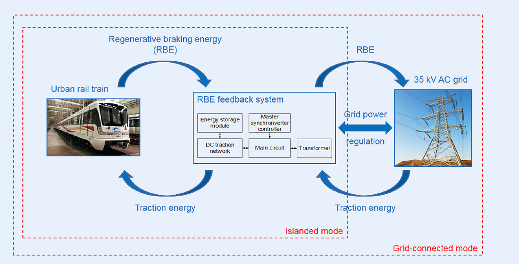
2.1. Structure of the System

The conventional RBE feedback system is shown in Figure 1a. Composed of the contact rail and return rail, the DC traction network supplies power for the train in operation. When the train accelerates, the DC bus voltage decreases, the energy from the 35 kV AC grid is rectified through a 24-pulse rectifier, feeding the DC traction network of urban rail transit. When the train brakes, the DC bus voltage rises and exceeds the threshold value, and RBE of the train obtained from the DC side is fed back to the AC grid through the high-power three-phase PWM inverter [25]. Compared with the conventional RBE feedback system, the rectifier and inverter function can be realized with the same equipment in the synchronverter-based RBE feedback system, as shown in Figure 1b. The system operates in both rectifying mode and inverter mode, autonomously supplies traction energy to the DC side and feeds the RBE back to the AC grid. In addition, the system can be self-synchronized with the grid and make appropriate responses on the basis of changes in the voltage amplitude and frequency of the grid.
The RBE feedback system consists of a main circuit, a transformer, an energy storage module and a master controller, as illustrated in Figure 2. The energy storage module is connected in parallel with the DC traction network, and the master controller generates drive signals to control the main circuit. The energy storage module is designed as an auxiliary module to further maintain the stability of the DC bus voltage.
The main circuit consists of a DC traction network, a three-phase bi-directional converter, an isolating transformer and an AC grid, as shown in Figure 3. The filter capacitor Cdc in Figure 3 is designed to suppress the harmonic components on the DC side, and the AC side LCL filter can perfectly weaken the high-order harmonics of the output current [26]. The inverter side inductance Ls of the LCL filter is used to suppress the current ripple produced by power electronic switches. The grid-side filter inductance Lg of the LCL filter further weakens the alternating current ripple and limits the impulse current at the moment of grid-connection [27,28,29]. The isolating transformer is applied for electrical isolation and voltage boost of the converter output voltage. To further ensure the stability of the DC bus voltage, an energy storage module is designed for auxiliary energy storage, which consists of an accumulator and a Buck/Boost DC-DC converter, as shown in Figure 4. The double closed-loop control algorithms applied in the charging and discharging mode of the energy storage module are shown in Figure 5.
The lack of damp and inertia of generators makes the conventional PWM RBE feedback system more sensitive to power fluctuations [15]. By using the synchronverter, the system can synchronize with the grid autonomously and participate in the management of the grid. Moreover, the synchronverter can make corresponding adjustments according to the changes of grid frequency and voltage under normal and abnormal conditions, thus presents good dynamic performance. Hence, the controller in this paper is based on the synchronverter, as shown in Figure 6, generating the control instruction e and the PWM signal of each IGBT of the converter.
According to the characteristics of the synchronous generator (SG), the rotor angle relative to the a-phase stator winding of the SG is θ. iabc is defined as the three-phase stator current of the SG and Rs and Ls are the resistance and inductance of the stator winding, respectively [15]. When defined as:
{ sin θ ˜ = [ sin θ sin ( θ 2 π 3 ) sin ( θ 4 π 3 ) ] cos θ ˜ = [ cos θ cos ( θ 2 π 3 ) cos ( θ 4 π 3 ) ]
the reverse electromotive force e = [ea eb ec]T, generated by rotor motion in stator windings, can be expressed as follows:
e = M f i f θ ˙ sin θ ˜
where Mf is the maximum mutual inductance between the excitation winding and the three-phase stator winding and if is the field current of the rotor. The SG needs to follow:
θ ¨ = 1 J ( T m T e D P θ ˙ )
where Tm is the mechanical torque, Te is the electromagnetic torque, J is the moment of inertia and DP is the damping coefficient. Assuming that the number of pole-pairs is 1, the electromagnetic torque Te can be calculated as:
T e = M f i f ( i ,   sin θ ˜ )
According to the electromagnetic transient relationship, the output active power is expressed as:
P = M f i f θ ˙ ( i ,   sin θ ˜ )
Moreover, the output reactive power is expressed as:
Q = M f i f θ ˙ ( i ,   cos θ ˜ )
According to the mathematical model of the SG, the master controller of the RBE feedback system can be obtained. The specific control strategy is discussed in Section 2.2.

2.2. Control Strategy of the System

2.2.1. Overall Control Strategy

The overall control strategy is presented in Figure 7. Before the grid-connection, the amplitude, frequency and phase of the output control instruction e are supposed to be synchronized with those of the AC grid voltage [30]. The Vset is the rated DC bus voltage, Vut/Vlt is the upper/lower threshold value of the traction network voltage, fut/flt is the upper/lower threshold value of the power grid frequency and vut/vlt is the upper/lower threshold value of the AC side voltage.

2.2.2. Rectifier Control

The rectifier controller is shown in Figure 8, which consists of a self-synchronization unit, a P-f control loop, a Q-V control loop and a DC bus voltage loop. The difference value between the voltage Vdc and the reference voltage Vset is fed into the PI controller to determine the compensation value of the traction energy.
Due to the reverse of the stator current, the mechanical motion equation of the rectifier controller is represented as:
J d ( θ ˙ θ ˙ n ) d t = T e D P ( θ ˙ θ ˙ n ) T m ,
where the J is the virtual moment of inertia, θ ˙ is the angular frequency of the output control instruction e, θ ˙ n is the rated angular frequency of the power grid, Te is the virtual electromagnetic torque, DP is the P-f control coefficient of the controller and Tm is the virtual mechanical torque.
The virtual mechanical torque Tm of the rectifier controller can be expressed as:
T m = ( k pv + k iv 1 s ) ( V set V dc ) , V dc V lt
According to the P-f control loop, the grid frequency can be regulated as:
θ ˙ = 1 J s [ D P ( θ ˙ r θ ˙ ) + T e T m ] ,
where θ ˙ r is the reference value of the grid angular frequency. Hence, the frequency droop control can be realized through the coefficient DP, and the phase θ of the voltage e can be controlled by the angular frequency θ ˙ . The coefficient DP can be defined as:
D P = Δ T Δ θ ˙ ,
where ΔT is the torque variation and Δ θ ˙ is the difference value between θ ˙ and θ ˙ r . The greater is Δ θ ˙ , the greater is ΔT, which regulates the controller output frequency.
In this paper, before all switches of the converter are switched on, the control instruction is supposed to be synchronized with the transformer primary side phase voltage vpg. As shown in Figure 8, a PI control loop plus a virtual current control loop can form a self-synchronization unit. The reference angle frequency θ ˙ r , generated by the PI controller, makes the difference between the controller output angle frequency θ ˙ and the reference value θ ˙ r gradually approach zero, thus keeping the controller frequency consistent with the grid frequency. The reference angular frequency θ ˙ r can be expressed as:
θ ˙ r = θ ˙ n ( k pf + k if 1 s ) Δ T
During the self-synchronization, the current i is 0 and the controller cannot generate the virtual electromagnetic torque Te. Consequently, the virtual current is is fed into the Q-V control loop to generate Te, realizing the voltage synchronization. In this sense, the virtual current is expressed as:
i s = 1 L s + R ( e v pg ) ,
where L is the virtual inductance and R is the virtual resistance. Only when the virtual current is drops to 0 can the converter be connected to the power grid.
In the grid-connected rectification mode, the practical grid current i is used for control. It is important to notice that the direction of the input grid current i in the rectifier controller is opposite to the direction of the current iabc in Figure 8. The reference directions of Te, P and Q are consistent with those in the inverter mode, for the sake of analysis.

2.2.3. Inverter Control

The inverter controller is shown in Figure 9, which is mainly composed of a P-f control loop, a Q-V control loop and a self-synchronization unit. The inverter controller can not only feed RBE into the grid, but also regulate the active power and the reactive power of the grid.
The mechanical motion equation of the inverter controller is represented as:
J d ( θ ˙ θ ˙ n ) d t = T m D P ( θ ˙ θ ˙ n ) T e
Similar to the rectifier controller, a DC bus voltage loop is introduced to determine the amount of RBE. When the train brakes, the DC bus voltage Vdc rises, Tm is determined by the variation of the Vdc. When Vdc is in the threshold range and Tm is determined by a set value Pset/ωn. In this sense, the virtual mechanical torque Tm can be calculated as:
T m = { ( k pv + k iv 1 s ) ( V dc V set ) , V dc V ut P set ω n , V lt < V dc < V ut
Under regenerative braking of the train, the DC bus voltage Vdc rises and RBE is fed back to the AC grid accordingly. When the grid frequency changes, the inverter controller starts the P-f control loop. When the grid voltage changes, the inverter controller starts the Q-V control loop.

3. Parameter Design of the System

3.1. System Capacity Design

To determine the system capacity, the traction calculation of the train operation and the DC bus voltage should be carried out first. According to the traction power supply standard [31], the rated line voltage of the AC side is 35 kV, the rated input voltage of the DC side is 1500 V and the output frequency of the system is 50 Hz ± 0.5%. For the sake of convenience, assume that the train is in AW2 full-loaded condition without mechanical braking and the traction power can be 100% converted to kinetic energy [32,33,34,35]; then, the traction calculation can be operated according to the parameters in Table 1.
Piecewise linearizing the traction–velocity curve of the subway in [36], the function of the traction T can be approximately expressed as:
T = { 370000 , 0 < v 40 3.6 23400 v + 630000 , 40 3.6 < v < 80 3.6
where the unit of the velocity v is m/s. Then, the so-called Davis equation [37] is applied to calculate the resistance of the train during operation, which can be calculated as:
R = 6.4 × M + 130 × n + 0.14 × M × v + [ 0.046 + 0.0065 × ( N 1 ) ] × A × v 2
Assuming that the train is running with the fastest traction strategy and brakes at maximum braking force, the dynamic curves of the running can be obtained, as shown in Figure 10. In Figure 10, the urban rail train starts to run at a variable acceleration at 0 s in the process of running between two stations. After reaching the maximum running speed at about 25 s, the train runs at a uniform speed. At 170 s, the train starts to brake with the maximum braking force until it stops. During the operation, the maximum traction power is 3 MW and the maximum braking power is 5.5 MW.
When a train runs between two stations, the starting station and the terminal station are each a traction substation [4]. Establish two traction substations as two nodes, the train as an ideal current source, the position of the train as a node and the DC traction network as a time-varying resistive network. According to the Nodal voltage equation, the voltage for two traction substations can be obtained, as shown in Figure 11. In Figure 11, we can see that the peak value of the traction network voltage is 1620 V; the voltage variation accounts for 8% of the rated voltage.
On the basis of above traction calculation results, the capacity of the synchronverter-based RBE system of urban rail transit is designed to be 10 MVA, the maximum variation of traction network voltage is 150 V and a traction network voltage variation of 120 V corresponds to an active power variation of 6 MW.

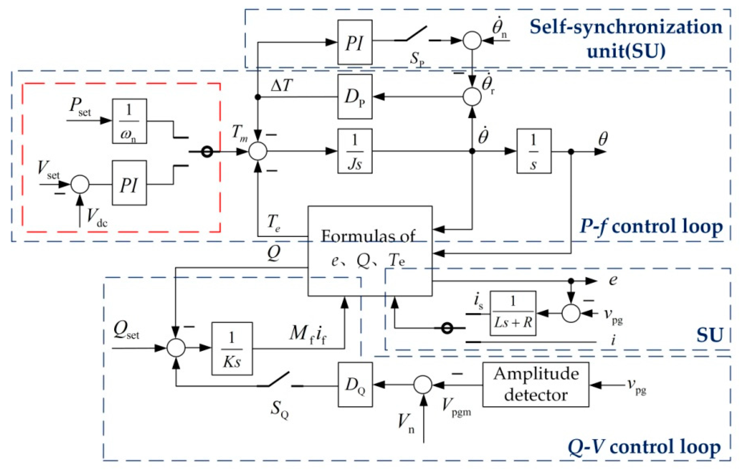
3.2. Parameter Design of the Master Controller

Taking the case of the inverter controller, the parameters of the controller can be designed based on above traction calculation results. The voltage fluctuation of the traction network does not exceed 10%, the frequency fluctuation of the grid does not exceed 0.5% and the voltage fluctuation of the grid does not exceed 10%.

3.2.1. Parameter Design of the P-f Control Loop

Firstly, the small signal model of the P-f control loop in Figure 9 is established as follows:
{ T m = T m 0 + T ^ m T e = T e 0 + T ^ e ω = ω n + ω ^ δ = δ n + δ ^ P = P 0 + P ^
where δ is the phase difference between the converter output voltage and the grid voltage. At the steady state, the phase of the AC side voltage is approximately equal to that of the grid voltage, thus sin δ0 = δ0. Ignoring the secondary disturbance term [39,40], the small signal expression can be represented as:
{ P ^ m = T ^ m ω n P ^ = T ^ e ω n + T e 0 ω ^ T ^ e ω n J d ω ^ d t = T ^ m T ^ e D P ω ^ d δ ^ d t = ω ^ P ^ = 3 E 0 V pg X δ ^
where E0 is the steady-state value of the controller output voltage e and X is the total impedance of the AC side of the converter. Using the Laplace transformation, the closed-loop transfer function of the P-f control loop can be obtained:
G f ( s ) = P ^ P ^ m = 3 E 0 V pg J X ω n s 2 + D P X ω n s + 3 E 0 V pg = ω n 2 s 2 + 2 ζ ω n s + ω n 2
The natural oscillation angular frequency ωs and the damping ratio ζ can be calculated as:
{ ω s = 3 E 0 V pg J X ω n ζ = D 2 ω n X 3 J E 0 V pg
When the natural oscillation angular frequency ωs is 150 rad/s, the damping ratio ζ is 1 and the impedance X is 0.005, the moment of inertia J can be 16. The P-f droop coefficient DP can be calculated as:
D p = Δ T Δ θ ˙ = Δ P 2 π f n · 2 π Δ f
For the P-f control loop, a 0.5% change in the grid frequency corresponds to a 100% change in the active power.

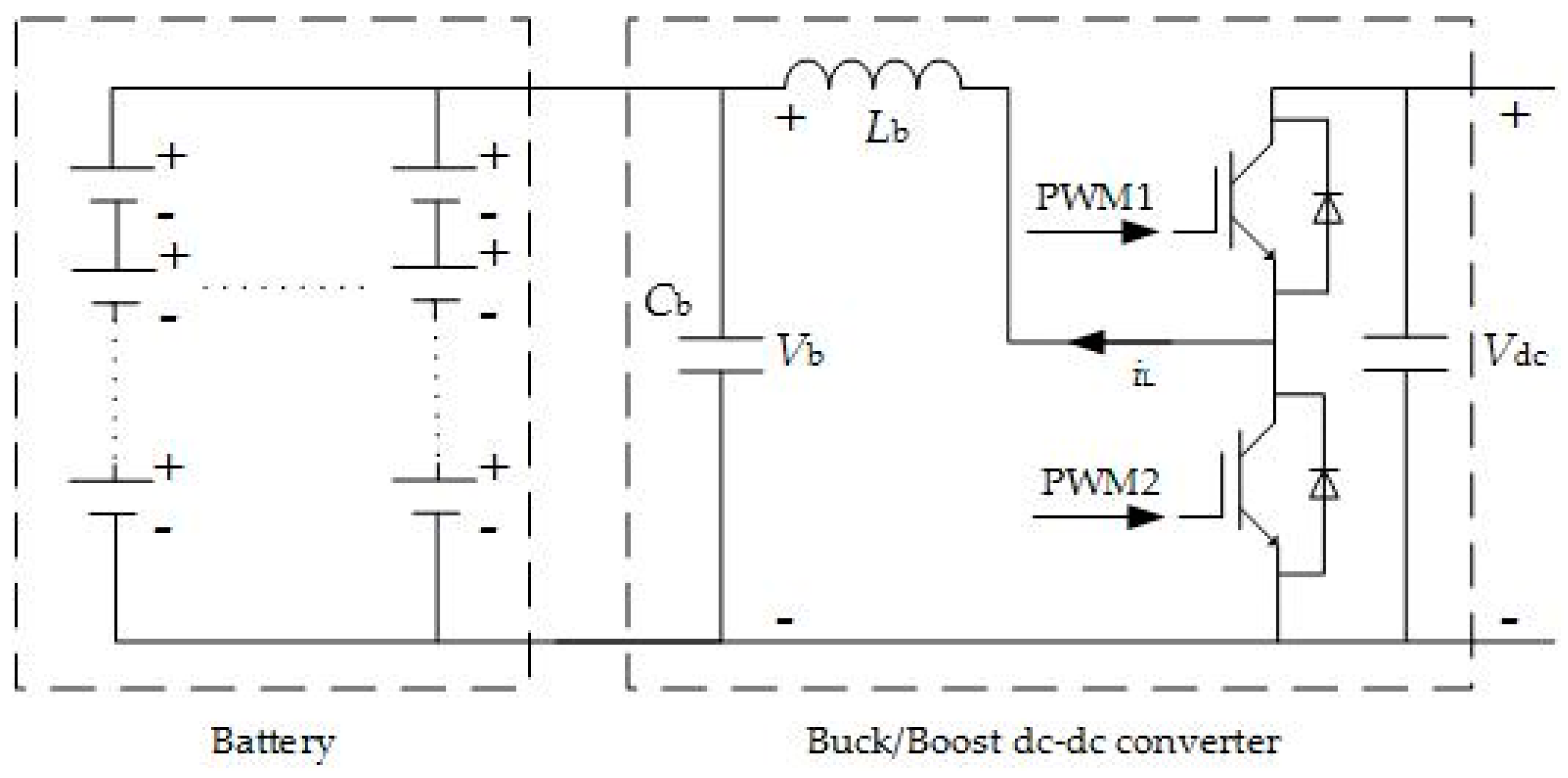
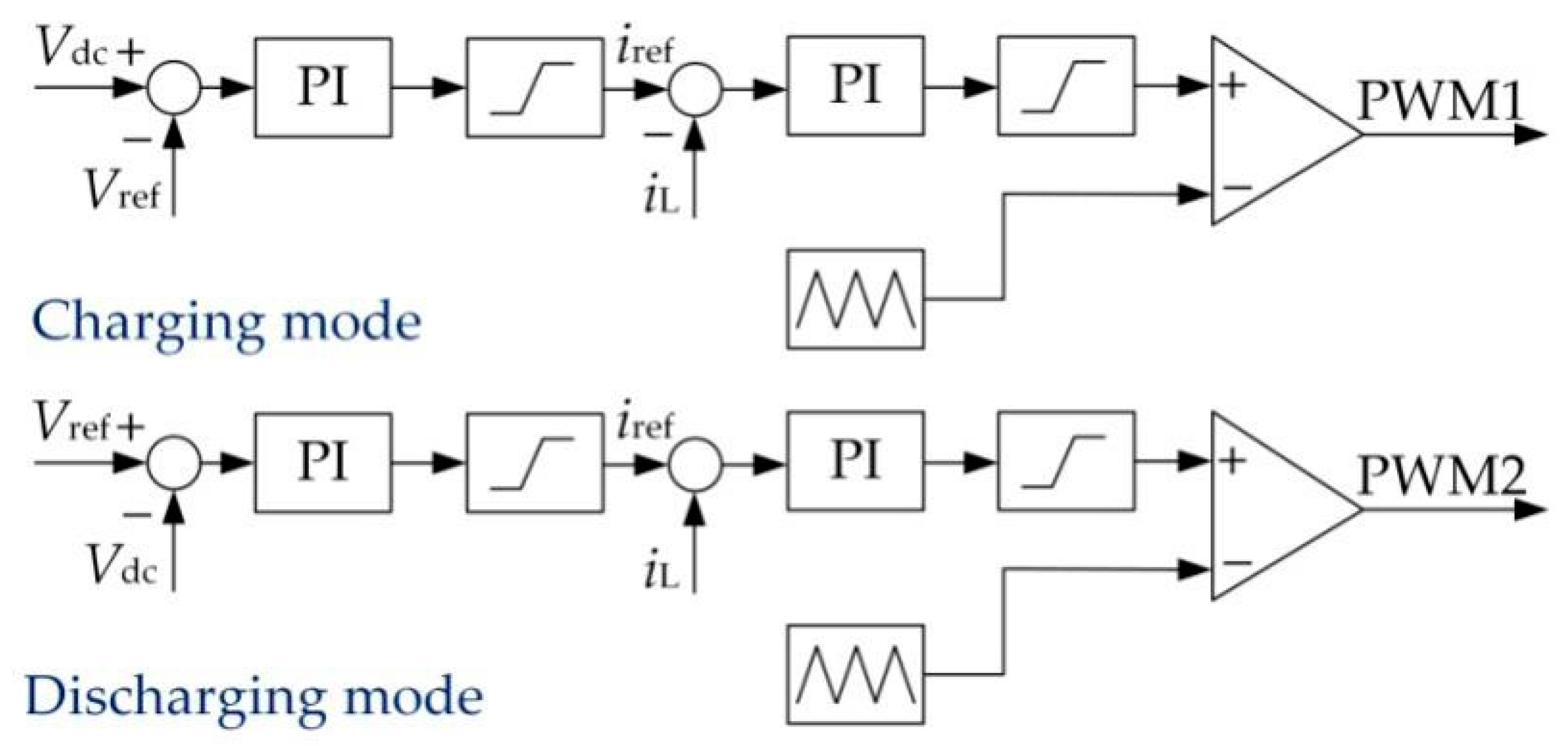
3.2.2. Parameter Design of the DC Bus Voltage Control Loop

The active power of the DC side can be approximately equal to the active power of the AC side when the effect of the parasitic resistance of the converter is ignored. In this sense, the synchronverter output active power P can be calculated as:
P = V dc ( V dc R eq + C dc d V dc d t ) ,
where Req is the equivalent resistance of the AC side and Cdc is the filter capacitance of the DC side. The small signal expression of the output active power P is represented as:
P ^ = V dc 0 ( 2 V ^ dc R eq + C dc d V ^ dc d t )
Using the Laplace transformation, combined with the P-f control loop transfer function, the transfer function of the DC bus voltage control loop can be obtained:
G v ( s ) = ( k p + k i ) ω n ω s 2 R eq s ( s 2 + 2 ζ ω s s + ω s 2 ) V dc 0 ( R eq C s + 2 ) = ω n R eq k i 2 V dc 0 ( k p k i s + 1 ) s [ ( s ω s ) 2 + 2 ζ s ω s + 1 ] ( R eq C 2 s + 1 )
From Equation (24), we can see that the amplitude–frequency characteristic curve of the DC bus voltage control loop transfer function has three transition frequencies: 2/ReqC, ki/kp and ωs. Based on above parameter design, we can determine that 2/ReqC is less than 1 and ki/kp, the reciprocal of the integration time, is generally greater than 1. In this sense, the bode plot of the DC bus voltage loop transfer function [41] can be obtained, as depicted in Figure 12.
The cut-off frequency ωc is the angular frequency corresponding to the intersection point of the curve and the 0dB line, as shown in Figure 12, which means ki/kp < ωc < ωs. At the point of the cut-off frequency ωc, A(ω) is 1. Moreover, assuming ki/kp is r, the PI control parameters of the DC bus voltage loop are calculated as:
{ k i = V dc 0 ω c ( ω s 2 + ω c 4 ω s 2 2 ω c 2 + 4 ζ 2 ω c 2 ) ( 4 + R eq 2 C dc 2 ω c 2 ) ω s ω n R eq r 2 + 1 k p = k i r ω c ,
where Vdc0 is 1500 V, ωn is 100π and ωc is less than twice of the power frequency [19]. If ωc is 100π, ωs is 150 rad/s, ζ is 1 and r is 4, kp can be 50 and ki can be 720.

3.2.3. Parameter Design of the Q-V Control Loop

For the Q-V control loop, a 0.5% change in the grid phase voltage amplitude corresponds to a 100% change in the reactive power. According to the reactive power compensation demand, the maximum reactive power variation ΔQ of the system is 6 MW. The Q-V droop coefficient DQ is:
D Q = Δ Q Δ V ,
where ΔV is the variation of the primary side phase voltage Vpgm of the transformer, which is selected to be less than 10% of the Vpgm. In addition, the gain K is calculated as:
K = ω n D Q τ v ,
where τv is the time constant of the Q-V control. The response speed of the system voltage inner loop control circuit is related to the gain K. The smaller is K, the faster is the response speed of the system.

4. Results and Discussion

4.1. Simulation Results

Based on the simulation model, the dynamic response of the RBE feedback system under grid normal and abnormal conditions were verified, with the parameters shown in Table 2.

4.1.1. Simulation under Grid Normal Condition

In the islanded mode, the system is in self-synchronization. The circuit breaker is switched on at 2 s. The system output frequency f, output active power P and output reactive power Q are shown in Figure 13.
At the time of grid connection, the variation of the output frequency f, output active power P and output reactive power Q are all far less than the rated value, as shown in Figure 13, having little impact on the grid. Moreover, the regulation speed of the system is less than 0.1s, and the output frequency f, active power P and reactive power Q are all restored in 0.1 s. The phase voltage va and phase current ia of the AC side with harmonic analysis are shown in Figure 14. As shown in Figure 14a,b, the output AC side phase voltage basically remains unchanged at 2 s, and the rms value of output AC side phase current rises from 0 to 85 A, far less than the rated primary side phase current of the transformer (7697.8A), which shows the smooth grid-connection of the system. As shown in Figure 14c,d, the total THD of the voltage injected into the AC grid is 0.03% and the total THD of the current is 1.14%, both less than 5%, which meets the GB/T 14549–1993 public power grid harmonic standard.
Simulation conditions in grid-connected mode:
  • Self-synchronization: The system starts to make self-synchronization with the grid at 0 s.
  • Traction: The train accelerates at 3 s, and the traction network voltage drops to 1380 V.
  • RBE feedback: The train starts to brake at 9 s, and the traction network rises to 1620 V.
  • Q-V control: Grid line voltage rms value drops to 33.25 kV at 15 s and rises to 35 kV at 18 s.
  • P-f control: The grid frequency rises to 50.05 Hz at 21 s.
As shown in Figure 15, the train accelerates at 3 s, the DC bus voltage drops and the controller works in the traction mode, thus the traction network voltage is restored to 1500 V in 3 s. Then, the train brakes at 9 s, the traction network voltage rises and the system works in the RBE feedback mode, thus the traction network voltage is restored to 1500 V again in 3 s. As shown in Figure 16, when the train accelerates, the grid supplies 6 MW traction energy for the traction network. When the train is under regenerative braking at 9 s, the DC traction network feeds 6 MW RBE back to the AC grid. When the amplitude of the grid line voltage drops by 5% at 15 s, the output reactive power rises by 50%, that is the reactive power needed of the AC grid is compensated by the DC side. When the grid line voltage rises to 35 kV at 18 s, the output reactive power drops 3 Mvar accordingly. When the grid frequency rises by 0.1% at 21 s, the system frequency is synchronized to 50.05 Hz in a few seconds and the output active power rises by 20%, which means the excess active power of the AC grid is transmitted to the DC side. In this way, the power of the grid can be regulated.
Simulation condition of the energy storage module in the islanded mode:
  • Charging mode: The traction network voltage rises to 1620 V at 1 s.
  • Discharging mode: The traction network voltage drops to 1380 V at 3 s.
As shown in Figure 17, the traction network voltage rises to 1620 V at 1 s; the storage module works in the charging mode, absorbing 6 MW active power; and the traction network voltage is restored to 1500 V after fluctuation. Then, the traction network voltage drops at 3 s; the storage module works in the discharging mode, releasing 6 MW active power; and the traction network voltage is restored to 1500 V after fluctuation.
Simulation condition of the energy storage module in the grid-connection mode:
  • Self-synchronization mode: The system starts to make self-synchronization at 0 s.
  • Grid-connection mode: The system is connected to the grid at 2 s.
  • P-f control: The grid frequency rises to 50.05 Hz at 3 s.
As shown in Figure 18, at 3 s, as the grid frequency fg rises, the system frequency f synchronously rises to 50.05 Hz. Accordingly, the output active power P drops to −1.6 MW, which means the excess energy of the AC grid is transmitted to the DC side, and the storage module works in the charging mode, absorbing 1.6 MW active power transmitted from the AC side.
The simulation results of the energy storage module show that, when the system is off the grid, the energy storage module can absorb RBE of the DC traction network as an auxiliary module and feed it back to the DC traction network when necessary. Moreover, when the system is connected to the grid, the energy storage module can provide the energy needed for active/reactive power regulation of the grid, without affecting the stability of the DC bus voltage.

4.1.2. Simulation under Grid Faults

Simulation conditions:
  • The converter is connected to the power grid at 1 s.
  • The grid line voltage drops by 50% at 2 s and restores at 2.1 s.
  • The grid frequency drops by 1% at 3 s and restores at 3.1 s.
As shown in Figure 19, when the grid frequency plummets at 2 s, the system frequency drops accordingly. When the grid frequency restores at 2.1 s, the system frequency is restored quickly. The output voltage of the system drops slightly when the grid voltage plummets at 3 s and restores quickly after the grid fault is cleared, which shows a great fault ride-through capability of the system.
Based on above simulation results, when the train is in traction mode, the system can transmit the corresponding amount of traction energy to the DC traction network to compensate the traction network energy, according to the variation of DC bus voltage. When the train is braking, RBE of the train is fed back to the AC grid. In addition, the above results also show that the system has a good grid power regulation capability and fault ride-through capability.

4.2. Experimental Results

Due to the restricted experimental laboratory conditions, the system function was verified by a scaled-down prototype. As shown in Figure 20, the system model prototype is composed of a power supply, a DSP module, a drive circuit, a sampling circuit and a main power circuit. The DC side voltage of the model is 140 V, and the rated phase voltage of the AC side is 50 V.
As shown in Figure 21a, when the DC bus voltage Vdc rises by 14 V, the system works in the RBE feedback mode. The AC side voltage Vabc is nearly constant, with the rms value of 50 V. The AC side current iabc rises to 1.5 A, which means the DC side feeds 225 W RBE back to the AC side. As shown in Figure 21b, when the system works in the rectifier mode, the AC side voltage Vabc is nearly constant, with the rms value of 50 V, and the AC side current iabc rises to 1.4 A. The phase difference between the current ia and the voltage va is 180°, which means the AC side feeds 212 W traction energy into the DC side.
Due to the limitation of the experimental conditions, the frequency and amplitude of the grid cannot be suddenly changed. In this sense, the compensation ability of the system for the active power and reactive power of the grid was verified by giving the active power and reactive power compensation instructions in the DSP program. As shown in Figure 22a, when the system is given 450 W active power, the rms value of the a-phase voltage va of the AC side remains constant and the rms value of the a-phase current ia rises to 2.9 A, with a power factor of 0.95. The system feeds 413.3 W active power into the grid, which is close to the given value. As shown in Figure 22b, when the system is given 450 Var reactive power, the rms value of the phase voltage va of the AC side remains constant and the rms value of the phase current ia rises to 3.1 A, with a power factor of 0.06. The system feeds 437.1 Var reactive power into the power grid, which is close to the given value.
In summary, the experimental results are consistent with the theoretical analysis done and the simulation results, showing the good dynamic performance of the system.

5. Conclusions

To improve the utilization of RBE of the train, a synchronverter-based RBE feedback system of urban rail transit is designed in this paper. The structure of the system is presented first, and then the control strategy is fully discussed. The synchronverter-based control proposed in this paper offers a more flexible and stable approach to give RBE back to the AC grid. Moreover, the capacity of the system is designed according to the traction calculation and the parameters of the system are analyzed in detail. The simulation and experimental results are both provided to verify the good dynamic performance of the system under grid normal condition and grid faults.
By using the synchronverter-based approach, the system supplies traction power to traction network when the train accelerates and feeds RBE back into the AC grid when the train brakes, in light of the variation of the DC bus voltage, thus keeping the DC traction network constant. Moreover, the system can be self-synchronized with the grid and make corresponding response according to the variation of the grid voltage or the variation of the grid frequency. In this sense, the grid power can be easily regulated and safeguarded by the system. Furthermore, the system dynamic performance under grid faults also shows a good fault ride-through capability of the system. In addition, with the help of the energy storage module, the system is able to operate in both islanded mode and grid-connection mode.
Consequently, by using the proposed synchronverter-based approach, the RBE feedback system becomes more flexible, effective and robust.
The calculation accuracy of the traction energy and RBE will be improved in future work, along with the impact of inductive load of lines.

Author Contributions

Conceptualization, S.L. and S.W.; methodology and software, S.L.; validation, S.L., S.X. and Y.Z.; writing—original draft preparation, S.L.; writing—review and editing, S.W. and J.C.V.; project administration, S.W.; and resources, supervision and funding acquisition, S.W. and J.M.G. All authors have read and agreed to the published version of the manuscript.

Funding

This work was supported by VILLUM FONDEN under the VILLUM Investigator Grant (No. 25920): Center for Research on Microgrids (CROM); www.crom.et.aau.dk.

Acknowledgments

The authors would like to show gratitude to PCC laboratory of Southwest Jiaotong University for providing equipment and suggestions on revision. In addition, we would like to thank the three prestigious reviewers for their valuable comments that improved the quality of this paper.

Conflicts of Interest

The authors declare no conflict of interest.

References

  1. Charalambous, C.A.; Cotton, I. A holistic stray current assessment of bored tunnel sections of DC transit systems. IEEE Trans. Power Deliv. 2013, 28, 1048–1056. [Google Scholar] [CrossRef]
  2. Wang, Y.F.; Zhao, Y.; Pang, J. Statistical analysis of urban rail transit lines in 2017 chinal express delivery of annual report on urban rail transit. Urban Mass Transit 2018, 21, 1–6. [Google Scholar]
  3. Liu, J.; Guo, H.; Yu, Y. Research on the cooperative train control strategy to reduce energy consumption. IEEE Trans. Intell. Transp. Syst. 2017, 18, 1134–1142. [Google Scholar] [CrossRef]
  4. Bae, C.-H.; Jang, D.-U.; Kim, Y.-G.; Chang, S.-K.; Mok, J.-K. Calculation of regenerative energy in DC 1500V electric railway substations. In Proceedings of the 2007 7th International Conference on Power Electronics, Daegu, Korea, 22–26 October 2007; pp. 801–805. [Google Scholar]
  5. Yang, Z.; Xia, H.; Wang, B. An overview on braking energy regeneration technologies in Chinese urban railway transportation. In Proceedings of the 2014 International Power Electronics Conference, ASIA, Hiroshima, Japan, 18–21 May 2014; pp. 2133–2139. [Google Scholar]
  6. Foiadelli, F.; Roscia, M.; Zaninelli, D. Optimization of storage devices for regenerative braking energy in subway systems. In Proceedings of the IEEE Power Engineering Society General Meeting, Montreal, QC, Canada, 18–22 June 2006; pp. 1–6. [Google Scholar]
  7. Chen, J.F.; Lin, R.; Liu, Y.C. Optimization of an MRT train schedule: Reducing maximum traction power by using genetic algorithms. IEEE Trans. Power Syst. 2005, 20, 1366–1372. [Google Scholar] [CrossRef]
  8. Yang, X.; Li, X.; Gao, Z.H.; Wang, H.; Tang, T. A cooperative scheduling model for timetable optimization in subway systems. IEEE Trans. Intell. Transp. Syst. 2013, 14, 438–447. [Google Scholar] [CrossRef]
  9. Su, S.; Li, X.; Tang, T.; Gao, Z. A subway train timetable optimization approach based on energy-efficient operation strategy. IEEE Trans. Intell. Transp. Syst. 2013, 14, 883–893. [Google Scholar] [CrossRef]
  10. Dominguez, M.; Fernández-Cardador, A.; Cucala, A.P.; Pecharromán, R.R. Energy savings in metropolitan railway substations through regenerative energy recovery and optimal design of ATO speed profiles. IEEE Trans. Autom. Sci. Eng. 2012, 9, 496–504. [Google Scholar] [CrossRef]
  11. González-Gil, A.; Palacin, R.; Batty, P. Sustainable urban rail systems: Strategies and technologies for optimal management of regenerative braking energy. Energy Convers. Manag. 2013, 5, 374–388. [Google Scholar] [CrossRef]
  12. Rufer, A.; Hotellier, D. A supercapacitor-based energy storage substation for voltage compensation in weak transportation networks. IEEE Trans. Power Deliv. 2004, 19, 629–636. [Google Scholar] [CrossRef]
  13. Guerrero, J.M.; Vasquez, J.C.; Matas, J.; De Vicuna, L.G.; Castilla, M. Hierarchical control of droop-controlled AC and DC microgrids—A general approach toward standardization. IEEE Trans. Ind. Electron. 2010, 58, 158–172. [Google Scholar] [CrossRef]
  14. Frilli, A.; Meli, E.; Nocciolini, D.; Pugi, L.; Rindi, A. Energetic optimization of regenerative braking for high speed railway systems. Energy Convers. Manag. 2016, 129, 200–215. [Google Scholar] [CrossRef]
  15. Zhong, Q.C. Virtual synchronous machines—A unified interface for smart grid integration. IEEE Power Electron. Mag. 2016, 3, 18–27. [Google Scholar] [CrossRef]
  16. Beck, H.P.; Hesse, R. Virtual synchronous machine. In Proceedings of the 9th International Conference on Electrical Power Quality and Utilization, Barcelona, Spain, 9–11 October 2007; pp. 1–6. [Google Scholar]
  17. Chen, Y.; Hesse, R.; Turschner, D.; Beck, H.-P. Comparison of methods for implementing virtual synchronous machine on inverters. In Proceedings of the International Conference on Renewable Energies and Power Quality, Santiago de Compostela, Spain, 28–30 March 2012; pp. 414–424. [Google Scholar]
  18. Gao, F.; Iravani, M.R. A control strategy for a distributed generation unit in grid-connected and autonomous modes of operation. IEEE Trans. Power Deliv. 2008, 4, 850–859. [Google Scholar]
  19. Zhong, Q.C.; Weiss, G. Synchronverters: Inverters that mimic synchronous generators. IEEE Trans. Ind. Electron. 2010, 58, 1259–1267. [Google Scholar] [CrossRef]
  20. Zhong, Q.C.; Nguyen, P.L.; Ma, Z. Self-synchronized synchronverters: Inverters without a dedicated synchronization unit. IEEE Trans. Power Electron. 2014, 29, 617–630. [Google Scholar] [CrossRef]
  21. Zhong, Q.-C.; Ma, Z.; Ming, W.-L.; Konstantopoulos, G. Grid-friendly wind power systems based on the synchronverter technology. Energy Convers. Manag. 2015, 8, 719–726. [Google Scholar] [CrossRef]
  22. Ming, W.L.; Zhong, Q.C. Synchronverter-based transformerless PV inverters. In Proceedings of the IECON 2014 40th Annual Conference of the IEEE Industrial Electronics Society, Dallas, TX, USA, 29 October–1 November 2014; pp. 4396–4401. [Google Scholar]
  23. Nguyen, P.L.; Zhong, Q.C.; Blaabjerg, F. Synchronverter-based operation of STATCOM to mimic synchronous condensers. In Proceedings of the 2012 7th IEEE Conference on Industrial Electronics and Applications (ICIEA), Singapore, 18–20 July 2012; pp. 942–947. [Google Scholar]
  24. Boldea, I. Control issues in adjustable speed drives. IEEE Ind. Electron. Mag. 2008, 2, 32–50. [Google Scholar] [CrossRef]
  25. Lu, Y.; Zhao, Y.; Zhao, X.; Li, G.; Zhang, C. Status analysis of regenerative braking energy utilization equipment in urban rail transit. In Proceedings of the 2017 IEEE Transportation Electrification Conference and Expo, Asia-Pacific (ITEC Asia-Pacific), Harbin, China, 7–10 August 2017; pp. 1–6. [Google Scholar]
  26. Liserre, M.; Teodorescu, R.; Blaabjerg, F. Stability of photovoltaic and wind turbine grid-connected inverters for a large set of grid impedance values. IEEE Trans. Power Electron. 2006, 21, 263–272. [Google Scholar] [CrossRef]
  27. Dannehl, J.; Wessels, C.; Fuchs, F.W. Limitations of voltage oriented PI current control of grid-connected PWM rectifiers with LCL filters. IEEE Trans. Ind. Electron. 2009, 56, 380–388. [Google Scholar] [CrossRef]
  28. Wang, J.; Yan, J.D.; Jiang, L.P. Seudo-derivative-feedback current control for three-phase grid-connected inverters with LCL filters. IEEE Trans. Power Electron. 2016, 31, 3898–3912. [Google Scholar] [CrossRef] [Green Version]
  29. Loh, P.C.; Holmes, D.G. Analysis of multiloop control strategies for LC/CL/LCL-filtered voltage-source and current-source inverters. IEEE Trans. Ind. Appl. 2005, 41, 644–654. [Google Scholar] [CrossRef]
  30. Zhong, Q.C.; Ma, Z.; Nguyen, P.L. PWM-controlled rectifiers without the need of an extra synchronization unit. In Proceedings of the IECON 2012–38th Annual Conference IEEE Industrial Electronics Society, Montreal, QC, Canada, 25–28 October 2012; pp. 691–695. [Google Scholar]
  31. Zheng, T.C. Urban Rail Transit Traction Power Supply System; China Railway Publishing House: Beijing, China, 2004. [Google Scholar]
  32. Lee, C.H.; Lu, C.J. Assessment of grounding schemes on rail potential and stray currents in a DC transit system. IEEE Trans. Power Deliv. 2006, 21, 1941–1947. [Google Scholar] [CrossRef]
  33. Zaboli, A.; Vahidi, B.; Yousefifi, S.; Hosseini-Biyouki, M.M. Evaluation and control of stray current in dc-electrified railway systems. IEEE Trans. Veh. Technol. 2017, 66, 974–980. [Google Scholar] [CrossRef]
  34. Chen, S.-L.; Hsu, S.-C.; Tseng, C.-T.; Yan, K.-H.; Chou, H.-Y.; Too, T.-M. Analysis of rail potential and stray current for taipei metro. IEEE Trans. Veh. Technol. 2006, 55, 67–75. [Google Scholar] [CrossRef]
  35. Xu, S.; Li, W.; Wang, Y. Effects of vehicle running mode on rail potential and stray current in DC mass transit systems. IEEE Trans. Veh. Technol. 2013, 62, 3569–3580. [Google Scholar]
  36. Chen, Y.; Chen, Y. Electric propulsion system of metro vehicle for Chengdu metro line 1. Railw. Locomot. Car 2009, 29, 52–55. [Google Scholar]
  37. Davis, W.J. The Tractive Resistance of Electric Locomotives and Cars; General Electric: Boston, MA, USA, 1926. [Google Scholar]
  38. Li, S.T.; Wu, S.R.; Yang, P.; He, S. Research on sychronverter-based regenerative braking energy feedback system of urban rail trains. In Proceedings of the 2019 14th IEEE Conference on Industrial Electronics and Applications (ICIEA), Xi’an, China, 19–21 June 2019. [Google Scholar]
  39. Trinh, Q.; Choo, F.H.; Wang, P. Control strategy to eliminate impact of voltage measurement errors on grid current performance of three-phase grid-connected inverters. IEEE Trans. Ind. Electron. 2017, 64, 7508–7519. [Google Scholar] [CrossRef]
  40. Yao, Z.; Xiao, L.; Guerrero, J.M. Improved control strategy for the three-phase grid-connected inverter. IET Renew. Power Gener. 2015, 9, 587–592. [Google Scholar] [CrossRef] [Green Version]
  41. Gao, B.T.; Xia, C.P.; Zhang, L.; Chen, N. Modeling and parameters design for rectifier side of VSC-HVDC based on virtual synchronous machine technology. Proc. CSEE 2017, 37, 534–544. [Google Scholar]
Figure 1. The RBE feedback systems: (a) the structure of the conventional RBE feedback system; and (b) the structure of the proposed RBE feedback system.
Energies 13 04418 g001
Figure 2. The diagram of the proposed RBE feedback system.
Energies 13 04418 g002
Figure 3. The main circuit of the synchronverter-based RBE feedback system.
Energies 13 04418 g003
Figure 4. The energy storage module of the RBE feedback system.
Energies 13 04418 g004
Figure 5. The double closed-loop controller.
Energies 13 04418 g005
Figure 6. Mathematical model of the synchronous generator.
Energies 13 04418 g006
Figure 7. Overall control strategy of the master controller.
Energies 13 04418 g007
Figure 8. Rectifier control strategy of the master controller.
Energies 13 04418 g008
Figure 9. Inverter control strategy of the master controller.
Energies 13 04418 g009
Figure 10. Traction calculation results of the train during running process: (a) speed–time curve; (b) distance–time curve; (c) acceleration–time curve; (d) current–time curve; and (e) active power–time curve.
Energies 13 04418 g010aEnergies 13 04418 g010b
Figure 11. Traction network voltage of two traction substations [38].
Energies 13 04418 g011
Figure 12. The amplitude–frequency characteristic curve of the DC bus voltage control loop transfer function.
Energies 13 04418 g012
Figure 13. The output frequency, output active power and output reactive power of the system in islanded mode and grid-connected mode: (a) output frequency f; (b) output active power P; and (c) output reactive power Q.
Energies 13 04418 g013aEnergies 13 04418 g013b
Figure 14. Simulation results of the AC side voltage and the current in the self-synchronization: (a) the output a-phase voltage va; (b) the output a-phase current ia; (c) harmonic analysis result of the output a-phase voltage va; and (d) harmonic analysis result of the output a-phase current ia.
Energies 13 04418 g014aEnergies 13 04418 g014b
Figure 15. The DC bus voltage of the system.
Energies 13 04418 g015
Figure 16. The system outputs under grid normal condition: (a) the grid frequency fg and the system output frequency f; (b) the system output active power P; and (c) the system output reactive power Q.
Energies 13 04418 g016
Figure 17. Dynamic response of the energy storage module to variation of the DC bus voltage: (a) the DC bus voltage; and (b) the active power of the module.
Energies 13 04418 g017
Figure 18. Dynamic response of the energy storage module to variation of the grid frequency: (a) the grid frequency fg and the system output frequency f; and (b) the energy storage module active power Pb and the system output active power P.
Energies 13 04418 g018aEnergies 13 04418 g018b
Figure 19. Dynamic response of the system to grid faults: (a) the reference frequency fn and the system output frequency f; and (b) the rms value of the system a-phase output voltage Va and the rms value of the grid voltage Vpga.
Energies 13 04418 g019aEnergies 13 04418 g019b
Figure 20. The experimental model of the synchronverter-based RBE feedback system.
Energies 13 04418 g020
Figure 21. The results of the system bi-directional flow experiment: (a) the phase voltage and the phase current of the AC side in the inverter feedback mode; and (b) the phase voltage and the phase current of the AC side in the traction mode.
Energies 13 04418 g021
Figure 22. System dynamic response: (a) a-phase voltage and a-phase current of the AC side in active power compensation mode; and (b) a-phase voltage and a-phase current of the AC side in reactive power compensation mode.
Energies 13 04418 g022
Table 1. Parameters of the traction calculation.
ParameterValue
Rated DC bus voltage Vdc1500 V
Distance between stations s3800 m
Maximum speed of the train v80 km/h
Maximum braking force of the train Z320 kN
Weight of the train M300 t
Alex number of the train n24
Carriage number of the train N (4M2T)6
Front area of the train A10 m2
Table 2. Parameters of the simulation.
ParameterValueParameterValueParameterValue
Cdc40 μFRdc0.03 ΩLs0.02 mH
Lg0.015mHRs0.005 ΩRg0.004 Ω
C127 μFRc1000 ΩR0.002 Ω
L0.002mHDP1.62 × 104DQ9.8 × 104
J16.21K6.16 × 106kpf5 × 10−6
kif5 × 10−5kpv50kiv650
Vut1550 Vfut50.05 Hzflt49.95 Hz
vut36 kVvlt34 kVVb1200 V
Rb0.03 ΩLg0.015 mHRg0.004 Ω
Lb0.1 mHCb68 μFkpv100
Kiv1200kpi1Kii120

