Article

Numerical Assessment of Heat Transfer and Entropy Generation of a Porous Metal Heat Sink for Electronic Cooling Applications

1
Department of Mechanical Engineering, Iran University of Science and Technology, 16844 Tehran, Iran
2
Department of Mechanical Engineering, University of Wisconsin-Milwaukee, WI 53211, USA
3
Department of Energy “Galileo Ferraris” (DENERG), Politecnico di Torino, 10129 Turin, Italy
4
Department of Mechanical Engineering, Amirkabir University of Technology, 1591639675 Tehran, Iran
*
Author to whom correspondence should be addressed.
Energies 2020, 13(15), 3851; https://doi.org/10.3390/en13153851
Submission received: 21 June 2020 / Revised: 21 July 2020 / Accepted: 22 July 2020 / Published: 28 July 2020
(This article belongs to the Special Issue Engineering Modeling of Advanced Heat Transfer Problems)

Abstract

:
In the present study, the thermal performance of an electronic equipment cooling system is investigated. The heat sink used in the current cooling system consists of a porous channel with a rectangular cross-section that is assumed to be connected directly to the hot surface of an electronic device. In this modeling, a fully developed flow assumption is used. The Darcy–Brinkman model was used to determine the fluid flow field. Since using the local thermal equilibrium (LTE) model may provide results affected by the error in metal foams, in the present research, an attempt has first been made to examine the validity range of this model. The local thermal non-equilibrium (LTNE) model taking into account the viscous dissipation effect was then used to determine the temperature field. To validate the numerical solution, the computed results were compared with other studies, and an acceptable agreement was observed. Analysis of the temperature field shows that if the fluid–solid-phase thermal conductivity ratio is 1 or the Biot number has a large value, the difference between the temperature of the solid phase and the fluid phase decreases. Moreover, the effect of important hydrodynamic parameters and the porous medium characteristics on the field of hydrodynamic, heat, and entropy generation was studied. Velocity field analysis shows that increasing the pore density and reducing the porosity cause an increase in the shear stress on the walls. By analyzing the entropy generation, it can be found that the irreversibility of heat transfer has a significant contribution to the total irreversibility, leading to a Bejan number close to 1. As a guideline for the design of a porous metal heat sink for electronic equipment, the use of porous media with low porosity reduces the total thermal resistance and improves heat transfer, reducing the total irreversibility and the Bejan number. Moreover, the increasing of pore density increases the specific porous surface; consequently, it reduces the total irreversibility and Bejan number and improves the heat transfer.

Graphical Abstract

1. Introduction

Today’s modern life is unimaginable without the use of electronic equipment such as personal computers (PCs). Demand for higher performance and faster computing has led to more electricity being consumed and more heat being generated [1]. This heat can shorten the life of the device or even damage it [2]. To ensure the safe operation of a PC, electronic components must operate within a certain temperature range to reduce the risk of damage or malfunction of the device; as a matter of fact, the performances of electronic equipment are highly dependent on temperature [3]. Hence, the issue of efficiently cooling electronic equipment has become a serious challenge for researchers. In this respect, using channels for cooling of these equipment was one of the solution to this challenge [4,5,6]. For instance, Fedorov and Viskanta [7] evaluated the flow and heat transfer in a microchannel heat sink which is operational for cooling the electronic packaging. The numerical model developed by these researchers has an appropriate agreement with the laboratory results. In addition, their numerical results show that the Poiseuille flow assumption is not always accurate and its validity must be examined in each specific case. In a numerical study, Kumar and Kumar [8] investigated the thermal performance and reliability of an electronic chip in a heat sink with six circular channels. They found that using nanoscale Al2O3/water nanofluid instead of water reduces surface temperature, energy consumption, and the thermal resistance of the electronic chip. They studied these effects to investigate the effects of different parameters on the thermal performance of electronic chips. Sarafraz et al. [9] evaluated the thermal performance of a Central Processing Unit (CPU) cooler that works with liquid gallium, CuO/water nanofluid, and water. In this study, the researchers used CPU in three modes, namely, standby, normal, and overload. From aspect of thermal performance, their results show that gallium performs more properly than nanofluid and water. Although use of gallium enhances the thermal efficiency, it has some disadvantages that are taken into account, such as rising the pressure drop. On the other hand, the use of nanofluid instead of water improves the heat transfer and also leads to a smaller pressure drop than that of gallium.
To worsen the situation, in new designs, there are attempts to make more electronic components per each unit of area [10]. Therefore, additional constraints must be considered during the design of a cooling system. There are some examples in this respect, such as having an electronic component with small size, the shortage of contact surface for heat transfer, the lack of use of large-sized cooling systems, and the high heat generated by a modern chip. These limitations have obliged engineers to design and make efficient cooling systems [11]. Porous metal foam is lightweight due to its high porosity [12]. It has a high surface density and, therefore, the cooling fluid touches more hot areas [13]. Due to the complex internal structure, it has the ability to create mixing within the fluid flow and to improve heat transfer [14]. It also has a high thermal conductivity [15]. In this regard, Zhang et al. [16] experimentally studied the thermal performance of a porous copper heat sink that is used to cool the CPU. The results of this study show that, as expected, the cooling capacity of porous copper (defined as the amount of removal heat from the heat sink space) rises with increasing the pressure difference between inlet and outlet, while it is almost constant for variations in the heat flux. Extra information about the usage of porous media in electronic equipment to enhance the thermal performance is provided for electronic chip in [17], different effects such Magnetohydrodynamics MHD in [18] and viscous dissipation in [19] for CPUs and in [20] for power LEDs.
The main purpose of numerical modeling applied to the analysis of porous metal foams for electronic equipment cooling is to select the geometric and fluid parameters to target optimized thermal efficiency. There are two principal perspectives on the study of heat transfer problems regarding porous media [21]. In the first view, the temperature difference between the solid phase and the fluid phase of the porous media is ignored, which is called the local thermal equilibrium (LTE) model [22]. Conversely, in the second view, the temperature difference between the solid phase and the fluid phase of the porous media is considered, and it is called the local thermal non-equilibrium (LTNE) model [23]. In addition, for the application that is relevant to the both parts of solid and fluid phases, it is significant to pay attention to the viscous dissipation in mathematical modeling of heat transfer problems, especially regarding porous media [24]. Entropy generation analysis turns out to be an effective and beneficial method for optimizing the thermal performance of different heat transfer systems, such as thermoelectric devices for electronic equipment cooling [25] through enclosures [26] and porous media [27]. The pioneer of using entropy generation analysis for thermal usages was Adrian Bejan. He used this method to analyze a heat exchanger during its operation [28]. This method of optimization takes into account an alternative to second law analysis. In addition, his book [29] describes thoroughly this method for different fields of engineering. The investigations of the entropy generation within the fluid current through the porous media under LTE conditions in pipes partially filled with a porous medium was carried out in [30], while LTNE conditions were analyzed in [30]. The effect of viscous dissipation on the entropy generation of a nanofluid current through microchannels filled with porous medium was investigated in [31,32].
To clarify the innovations of this article, the focus should be concentrated on the viscous dissipation effect and consideration of both the LTE and LTNE models in the simulation of heat transfer for a porous channel used as heat sink for electronic cooling applications. To the authors’ best knowledge, for the first time in this geometry and conditions relevant for the cooling of electronic equipment, the validity interval of the LTE model was presented. Furthermore, two different approaches for the adiabatic boundary conditions are considered and the results were compared to each other. In a recent paper, by applying the semi-empirical correlations, the properties of porous media such as K, k f e , k s e , h s f and A s f as the functions of two morphology parameters of porosity and pore density were calculated. This paper paves the way for the analyses of entropy generation following the investigation of the effects of porous media on the velocity and temperature fields and, ultimately, the appropriate parameters for enhancing the performance was cleared.
The paper is organized as follows: in Section 2, the problem configuration and simplifying assumptions are described. In Section 3, the mathematical formulation of the conservation laws in the porous media are presented, for both cases of LTE and LTNE. In Section 4, the numerical implementation of the model is described, together with a benchmark of the computed results against those of a test case available in the literature. After the superior suitability of the LTNE model for the problem at hand, in Section 5 the results of the analysis are presented in terms of effects of the porosity and pore density on the velocity, temperature and entropy generation fields. Conclusions are drawn in Section 6.

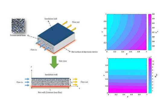
2. Problem Configuration and Assumption

Figure 1 shows the porous heat sink model used in numerical analysis. This model consists of a rectangular porous channel that is connected directly to the hot surface of an electronic device. This assumption is considered to simplify the solving approach. The length and height of the heat sink are introduced by L and H, respectively. In a real electronic device, the size of height is usually small and in the order of millimeter [20,33]. In this study, the height of the channel is considered 5 mm and the length of the channel is larger than the height and is 150 mm, which, according to the literature, are reasonable assumptions. The heat sink channel has a rectangular cross-section in which the cooling fluid uniformly enters from the one side and exits from another side. In this study, subcooled water at ambient temperature is selected as the cooling fluid. In order to simulate the heat generated by the electronic device, a uniform heat flux ( q ) is applied to the bottom surface of the channel. In this way, the working fluid flows through the porous media, and the generated heat is transferred to the working fluid by the porous media. To achieve a conservative design, all other sides of the heat sink are considered to be insulated. The following assumptions are used to extend the mathematical model:
  • The flow is steady, laminar, incompressible, and fully developed from hydrodynamics and thermal aspects.
  • Thermal resistance between the hot surface of the electronic device and the porous medium is neglected.
  • The thermo-physical properties of the porous medium are constant.
  • The porosity and pore density of the porous medium are varied parametrically in the range of 0.8 ε 0.98 and 10 ω 30 Part Per Inches (PPI).
  • The porous medium is assumed rigid, isotropic, and homogeneous and completely saturated with fluid.
  • Between the solid phase and the fluid phase of the porous medium, local thermal non-equilibrium conditions may exist.

3. Mathematical Formulation of the Problem

3.1. Steady Momentum and Energy Equations

In order to model the hydrodynamic and the heat field of the intended problem in the relevant computational domain, the Darcy–Brinkman model in Equation (1) and the LTNE model (Equations (2) and (3)) are used to describe the momentum and energy equations, respectively[31,34,35].
0 = dp dx μ f K u + μ f ε 2 u y 2
ρ f c p , f   ( u T f x ) = k fe 2 T f y 2 + h sf a sf ( T s T f ) + μ f K u 2 + μ f ε ( u y ) 2 .  
k se 2 T s y 2 h sf a sf ( T s T f ) = 0
In Equations (1)–(3) u , p , T f , and   T s are seepage velocity, pressure, temperature of the fluid phase, and temperature of the solid phase of the porous medium, respectively. In addition, K is the permeability, ε is the porosity, μ f is the viscosity of the working fluid, k fe is the effective thermal conductivity of the fluid phase, k se is the effective thermal conductivity of the solid phase, h sf is interstitial heat transfer coefficient, and a sf is surface area density of the metal foam. The values of a sf ,   k fe   and k se are computed following the relations in [36], while the values of the interstitial heat transfer coefficient h sf are obtained from the definition of the Nusselt number, Nu, based on the Zukaukas correlation for staggered cylinders [37], consistently with the recipe presented in [38]. The terms on the left-hand side of Equation (2) accounts for heat conduction in the fluid, for the interstitial heat transfer, for the viscous dissipation due to the Darcy term in the momentum equation (Equation (2)) and for the Brinkman term in Equation (2), respectively.
The condition of no-slip and constant heat flux dominates the bottom wall, as reported in Equation (4).
y = 0 :   u = 0 ,   T f = T s = T w , k se T s y k fe T f y = q w  
No-slip and adiabatic conditions are applied on the bottom wall. Two different approaches can be used to model the adiabatic boundary condition on the wall of a channel filled with porous media, and namely:
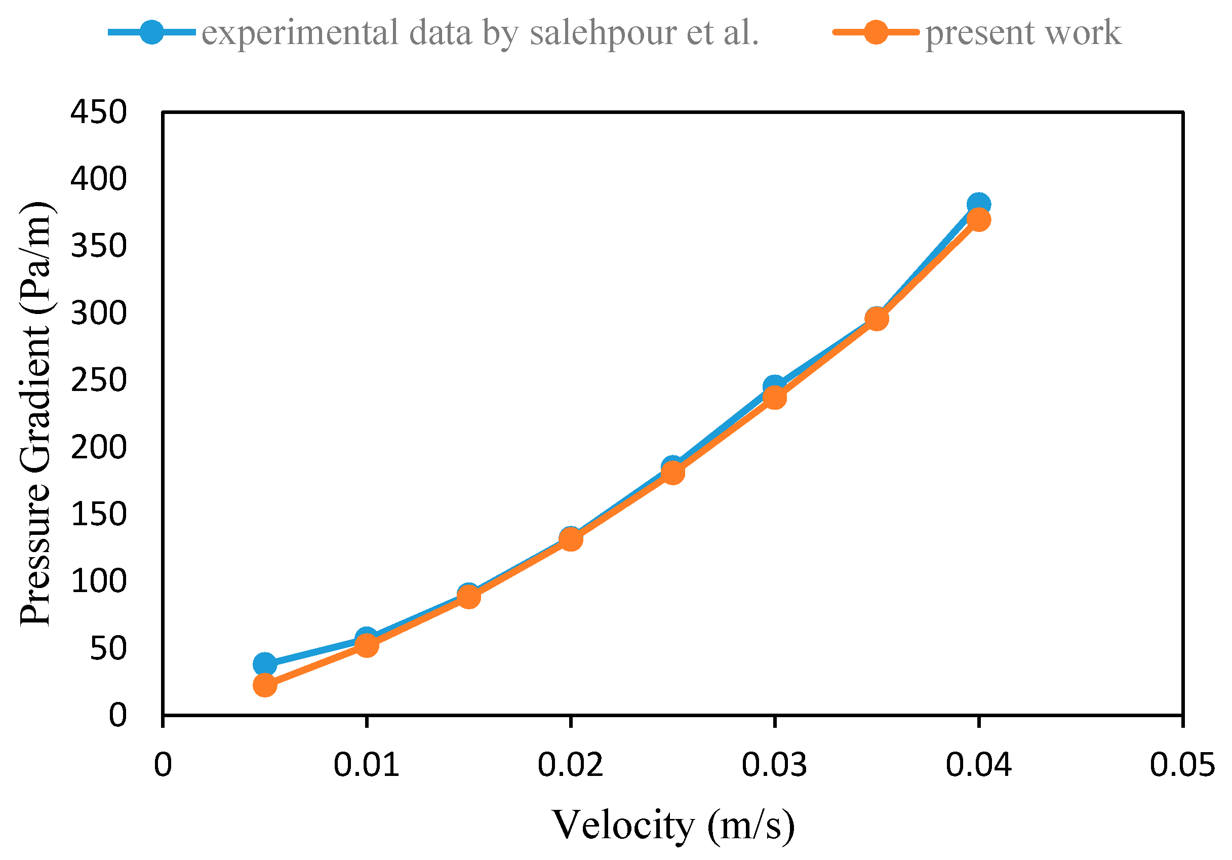
  • case A: The sum of the heat flux obtained from the solid phase and the fluid phase of the porous medium equals the imposed heat flux (null flux, for the case at hand).
  • case B: it is assumed that the heat flux of the fluid phase and the solid phase are zero, respectively. In other words, the temperature gradient for the fluid and solid phase is zero [39].
We retain both cases in our analysis, therefore the boundary conditions on the top side of the porous medium can be expressed as in Equation (5):
y = H :   u = 0 ,   Case   A : k se T s y + k fe T f y = 0 ,   T s = T f ,   Case   B :   T s y = T f y = 0
For a fully developed thermal flow, the temperature field is defined as follows [31,34]:
T i ( x , y ) = f f ,   s ( y ) + Ω x  
dT w dx = T ¯ f x = T ¯ s x = T f x = T s x = Ω = constant
By summing Equations (2) and (3), and integrating the relation obtained on the channel height, the following equation is obtained [31,32,35]:
ρ f c p , f   ( u T f x ) = k fe 2 T f y 2 + k se 2 T s y 2 + μ f K u 2 + μ f ε ( u y ) 2
ρ f c p , f H u m   T ¯ f x = q w + 0 H μ f K u 2 d y + 0 H μ f ε ( u y ) 2 d y
By combining Equations(9) and (6), the constant Ω can be expressed in the form [35] of Equation (10):
Ω = q w + 0 H μ f K u 2 d y + 0 H μ f ε ( u y ) 2 d y ρ f c p , f H u m
where u m is the average value of the seepage velocity in the vertical direction, defined in Equation (11)
u m = 1 H 0 H udy
In the LTE model, assuming that the temperature of the fluid and solid phase are equal (in other words, T f = T s = T te ), by combining Equations (2) and (3), an energy equation forms for the porous medium. Therefore, considering the LTE model, the energy equation is expressed as follows [35,36,40]:
Local thermal equilibrium model (LTE)
ρ f c p , f   ( u T te x ) = ( k fe + k se ) 2 T te y 2 + μ f K u 2 + μ f ε ( u y ) 2
The boundary conditions related to the LTE in Equation (12) can be written as follows [35,36]:
y = 0 :   T t e = T w , ( k fe + k se ) T te y = q w   a n d   y = H : T te y = 0
To make dimensionless the momentum and energy equations, we can consider the dimensionless parameters defined in Table 1 [35].
By substituting Equation (14) in Equations (1) to (5), as well as Equations (12) and (13), the dimensionless form of momentum, energy, and boundary condition equations related to the problem are presented in the form reported in Equations (15–17) for the LTNE model, with the corresponding boundary conditions in Equations (18) and (19), and in Equation (20) for the LTE model, with its boundary conditions in Equation (21).
0 = 1 + 1 ε 2 U Y 2 U Da
C U U m = k 2 θ f Y 2 + Bi ( θ s θ f ) + B r D a U 2 + B r ε ( U Y ) 2
0 = 2 θ s Y 2 Bi ( θ s θ f )
Y = 0 :   U = 0 ,        θ f = θ s = 0
Y = 1 :   U = 0 ,   Case   A : θ s Y + k θ f Y = 0 ,   θ s = θ f ,        Case   B :   θ s Y = θ f Y = 0
C U U m = ( 1 + k ) 2 θ t e Y 2 + B r D a U 2 + B r ε ( U Y ) 2
Y = 0 :   θ t e = 0 ,   Y = 1 : θ te Y = 0
where the parameter C in Equations (16) and (20) is defined according to Equation (22):
C = 1 + 0 1 Br Da U 2 dY + 0 1 Br ε ( U Y ) 2 dY
Note that the coefficients of the conservation laws in the dimensionless formulation are now expressed just in terms of dimensionless parameters including the porosity, the Darcy number, Da (i.e., the ratio between permeability and a reference surface), the Brinkman number, Br (i.e., the ratio of viscous heat generation to the external heat), and the conductivity ratio k .

3.2. Entropy Generation for LTNE Model

The volumetric rate of entropy generation in the intended heat transfer system can be deduced, according to [31,41], in the solid and fluid components of the porous media as reported in Equations (29) and (30), respectively:
s ˙ gen ,   s = k se T s 2 ( ( T s x ) 2 + ( T s y ) 2 ) h sf a sf ( T s T f ) T s
s ˙ gen ,   f = k fe T f 2 ( ( T f x ) 2 + ( T f y ) 2 ) + h sf a sf ( T s T f ) T f + μ f KT f u 2 + μ f ε T f ( u y ) 2
By summing Equations (22) and (23), the total entropy generation rate in the metal foam is obtained in Equation (31) [31,41]:
s ˙ gen = k se T s 2 ( ( T s x ) 2 + ( T s y ) 2 ) + k fe T f 2 ( ( T f x ) 2 + ( T f y ) 2 ) + h sf a sf ( T s T f ) 2 T f T s + μ f KT f u 2 + μ f ε T f ( u y ) 2
The first, second, and third terms in Equation (24) are related to heat transfer, and the fourth and fifth terms are related to fluid friction and viscous dissipation. The two irreversible terms are split in Equations (25) and (26), respectively, where the different reference temperature at the denominators clearly accounts for the temperature difference of fluid and solid components, intrinsic of the LTNE terms.
s ˙ HT = k se T s 2 ( ( T s x ) 2 + ( T s y ) 2 ) + k fe T f 2 ( ( T f x ) 2 + ( T f y ) 2 ) + h sf a sf ( T s T f ) 2 T f T s
s ˙ FF = μ f KT f u 2 + μ f ε T f ( u y ) 2
The dimensionless form of irreversible terms is presented in Equation (27) in the form of local volumetric entropy generation rates [31,41]:
N t o t = s ˙ gen H 2 k s   ,   N HT = s ˙ HT H 2 k s   ,   N FF = s ˙ FF H 2 k s ,
In the aforementioned correlation, the dominator used could be kfe or kse, but here, ks has been utilized. Because this parameter and H are constant, the effect of porosity on local volumetric entropy generation can be clearly seen. The average of total dimensionless irreversibility rate due to heat transfer and fluid friction are obtained locally by Equation (28) [31,41], so that a single value can be obtained by further integrating in the flow direction x, as shown in Equation (29).
N i ¯ = 0 1 N i dY , i = HT ,   FF ,   tot
N i = = 0 1 N i ¯ dX ,   i = HT ,   FF ,   tot
The Bejan number, which is the ratio of irreversibility due to heat transfer to total irreversibility, can be then calculated from Equation (30).
Be = N = HT N = tot

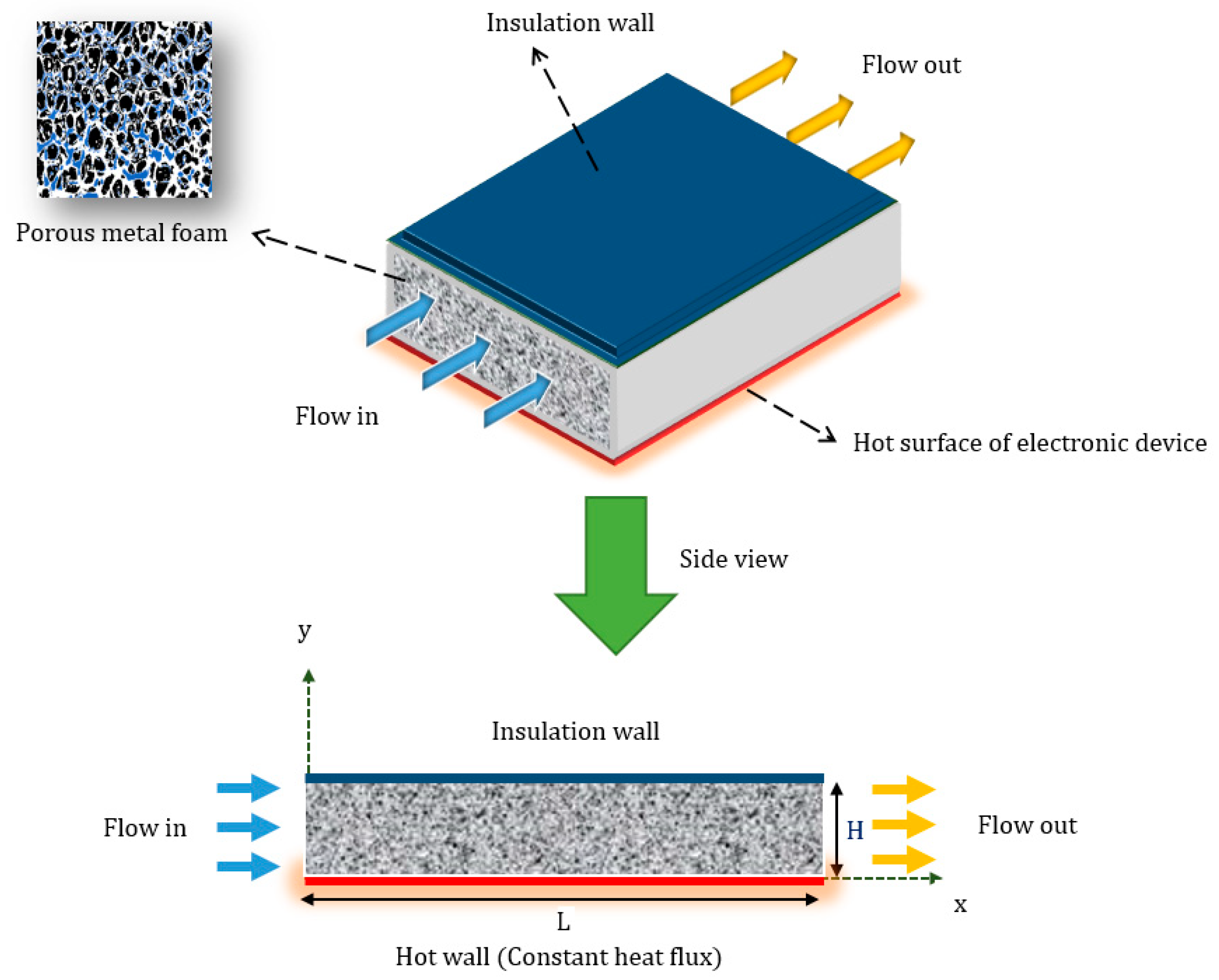
4. Numerical Model and Validation

In this section, the numerical implementation of the model is discussed. In this study, bvp4c code in the Matlab software was employed. The bvp4c script, predefined in Matlab, is a finite difference code for boundary value problems which relies on a collocation polynomial providing a C1-continuous solution based on an accuracy of fourth-order uniformly in the interval of integration [42]. According to a given initial mesh of points, the collocation algorithm divides the interval of integration into subintervals. Starting from an initial solution guess, after determining the numerical solution by solving the global system of algebraic equations for the specified boundary conditions at the collocation points on all the subintervals, the solver evaluates the error of the numerical solution on each subinterval based on the residual of the continuous solution. If the solution does not satisfy the tolerance criteria, set here equal to 10−9 (for both relative and absolute values), the solver adapts the mesh and repeats the process.
Before using the model to understand the thermal-hydraulic behavior of the porous block for different values of porosity and pore density, the model is first validated against a limited dataset of experimental values available in the literature.
First, the results of the numerical solution are compared with the values in the reference case presented in [43], for which now we better explain the test case in the manuscript revision. The working fluids considered as air and Nusselt number and dimensionless pressure in this comparison were obtained as in Equations (31–33).
P = K μ u m dp dx
Nu = q T w T f , b 4 H k f = k se k f 4 θ f , b
θ f , b = 0 1 θ f UdY 0 1 UdY
As shown in Figure 2a,b and Table 2, a very good agreement is found between the actual numerical solution and the reference values. Moreover, the results are validated with experimental data. In the study we consider, i.e., Salehipour et al. [44], a rectangular channel filled with porous media (copper foam) is investigated. They considered the Reynolds number in the range of 373 to 1186. The cooling fluid is water and the permeability and porosity are considered 1.774 × 10⁻⁷ (m2) and 0.9013, respectively. In addition, the width (W), height (H) and length (L) are stated as 50 mm, 20 mm and 430 mm, respectively. According to Figure 3, there is very good match between our computed results and the experimental data.

5. Results and Discussion

The main purpose of analyzing the results is to investigate the effect of geometric and flow parameters on the performance of the heat sink. For this purpose, the constant parameters of input used in numerical modeling are listed in Table 3.

5.1. Comparison of the LTNE Model and LTE Model

As mentioned in the previous sections, there are two different perspectives, named LTE and LTNE models, for modeling heat transfer problems in porous media. The use of the LTE model is not feasible in all cases, and it can only be used in ones where the difference between the solid and fluid phases of the porous medium is very small. Therefore, the main purpose of this sub-section is to find the reliability range of the LTE model. In Figure 4, the effects of the Biot number (Bi)—which is defined as the ratio of a porous medium’s ability to transfer heat to the conduction of the solid-phase and the fluid–solid-phase thermal conductivity ratio (k)—on the temperature of the solid phase ( θ s ) and the fluid phase ( θ f ) in the LTNE model as well as the equilibrium temperature ( θ t e ) in the LTE model are shown. It can be seen that when k is equal to 1 ( k fe = k s e ), the difference between the temperatures of the solid and fluid phases decreases (compare Figure 3a,c). Similarly, when the Bi number is large, the difference between temperatures of the solid and fluid phases also decreases. In addition, if k is close to 1, the equilibrium temperature is reached in between the regions between the temperature of the solid and fluid phases in the LTNE model. On the other hand, if k is small ( k fe k s e ) the equilibrium temperature is very close to the temperature of the solid phase. Note that a small value of k is expected for metal foams object of the present study, since the k value of the fluid and solid phase is about 0.08, which is considerably smaller than the thermal conductivity of the solid phase.

5.2. Velocity and Temperature Distribution

Figure 5 shows the effect of porosity and pore density on dimensionless velocity profiles. Due to the non-slip condition, the velocity profile starts to propagate from zero value on the channel walls and reaches its maximum value in the middle plate of the channel. Increasing the porosity increases the permeability of the porous medium and, thus, it reduces the resistance to fluid flow. Hence, according to Figure 5a, increasing the porosity reduces the velocity gradient in areas close to the wall. The maximum velocity value is also increased due to the decrease in the velocity gradient. The effect of pore density variations on the dimensionless profile of velocity can be seen in Figure 5b. Based on this figure, increasing the pore density strengthens the gradient of velocity in areas close to the walls. This phenomenon can be attributed to the decrease in permeability due to increasing the pore density. In another aspect, due to the fact that the velocity becomes uniform by increasing the pore density, thus, by an increase in pore density, the maximum value of the velocity in the middle plate of the channel decreases.
Figure 6 shows the temperature distribution contour of the fluid and solid phases of the porous media. The solid-phase thermal conductivity is much larger than the fluid-phase thermal conductivity. Therefore, there is a temperature difference between the solid and fluid phases of the porous medium, and the temperature of the solid phase is greater than the fluid one. Since the heat flux enters the channel from the bottom, the temperature close to the bottom wall is higher than the temperature of the top one. For both temperature distributions, the minimum value occurs at the inlet area of the channel close to the top wall. Additionally, the maximum value occurs in the outlet area close to the bottom wall, which is due to the heat flux presence and the viscous dissipation along the channel. In addition, it should be mentioned that the velocity and temperature fields are valid for laminar regime. In the subject literature, it became acceptable that due to the complex internal structure of the porous media, the turbulent regime occurs at a very large Reynolds number, so the domain of these fields supports a wide range [12,21].
Figure 7a illustrates the influence of porosity on the dimensionless temperature of both phases. The thermal resistance of the solid phase is much lower than the thermal resistance of the fluid phase. Hence, as expected, the temperature of the solid phase is closer to zero. In other words, the temperature difference between the solid phase and the hot wall is less. The lower the porosity, the greater the contribution of the solid phase to heat transfer. Besides, the solid phase has a much higher thermal conductivity than the fluid phase. As a result, the decrease in the porosity reduces the thermal resistance governing the heat transfer mechanism. Thus, the lower the porosity, the closer the temperature profile is to the temperature of the hot wall. Figure 7b shows the effect of the type of adiabatic boundary condition (case A and case B) on the dimensionless temperature profile. The type of adiabatic boundary condition only affects the temperature of the fluid phase on the upper wall (insulation wall). For case A, the temperature of the solid phase is equal to the temperature of the fluid phase, and this value for case B is less than the temperature of the solid phase.

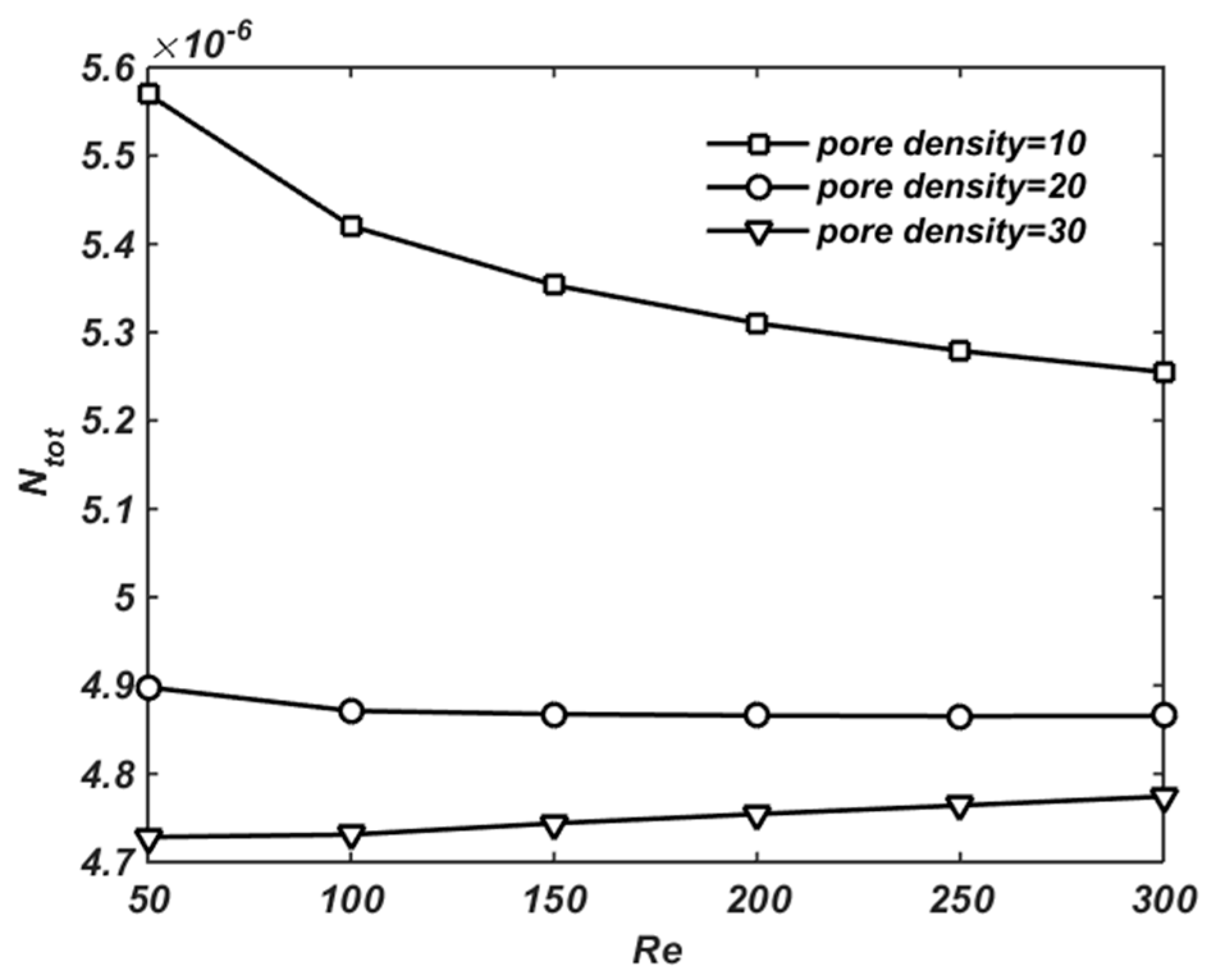
5.3. Entropy Generation Analysis

Figure 8 shows the distribution of the heat transfer irreversibility, fluid friction irreversibility, and total irreversibility. As can be seen from all three contours, the slope along the axial direction is very small. According to Figure 8a which illustrates the distribution of heat transfer irreversibility, the irreversibility in areas close to the hot wall is very intense. The reason for this phenomenon is the temperature gradient created by the heat flux generated by the electronic device. By moving away from the hot wall and approaching the insulation wall, the distribution of the heat transfer irreversibility decreases due to the reduction in the temperature gradient. Figure 8b shows the distribution of fluid friction irreversibility. According to Figure 5, the velocity gradient is intense in the areas close to the insulation wall and the hot wall. Hence, as expected, the friction irreversibility is high in this region. By moving away from the walls, the velocity gradient decreases and, thus, the irreversibility due to viscous dissipation decreases. On the other hand, in areas far from the walls and close to the middle plate of the channel, the velocity becomes maximum and uniform. Therefore, in these areas, the irreversibility of fluid friction is uniform and has larger values. Note, however, that the entropy generation due to viscous dissipation in several orders of magnitude is smaller than that due to the heat transfer. In Figure 8c, the total irreversibility distribution is evaluated. Total irreversibility is the sum of the fluid friction irreversibility and the heat transfer irreversibility. Since the fluid friction irreversibility is negligible compared to the heat transfer irreversibility (see Figure 8a,b), the trend of total irreversibility variations is similar to the trend of the heat transfer irreversibility.
Figure 9 shows the variation in the average total irreversibility ( N = t o t ) as a function of the Reynolds number (Re) in the different pore density. As shown in Figure 8, the total irreversibility has a behavior similar to that of the heat transfer irreversibility. According to Figure 5, increasing the pore density causes the velocity profile to be uniform at a shorter distance from the hot wall. Eventually, by increasing the pore density, a larger fraction of the hot surface is wetted by the fluid, and a more effective heat transfer can take place. Therefore, as shown in Figure 9, increasing the pore density decreases the value of N = t o t . When the pore density is equal to 10, the N = t o t decreases by increasing the Reynolds number. However, when the pore density is equal to 30, the N = t o t increases by increasing the Reynolds number. This is because by increasing pore density, the permeability of the porous medium decreases and, therefore, the shear stress on the wall increases. Thereafter, the resistance force is reinforced and, consequently, the viscous dissipation is augmented. As a result, the fluid friction irreversibility rises.
Figure 10 displays the variations in the average total irreversibility as a function of the Reynolds number at different values of porosity. According to this figure, increasing the porosity causes an increase in the total irreversibility. The reason for this phenomenon can be explained by the fact that the thermal conductivity of the solid phase is much larger than the thermal conductivity of the fluid phase. On the other hand, the lower the porosity, the larger s the role of the thermal conductivity of the solid phase in the heat transfer mechanism. Thus, as the porosity decreases, the thermal resistance of the heat transfer mechanism and entropy generation decrease. In addition, in low porosity, the effect of the Reynolds number on total irreversibility is low. When the porosity is low, since ks>>kf, the dominant heat transfer mechanism is conduction, whereas the Reynolds number only affects the convection mechanism. Hence, in low porosity, the Reynolds number does not affect the total irreversibility.
Figure 11a illustrates the variations in the Bejan (Be) number as a function of the Reynolds number in the various pore densities. Since the heat transfer irreversibility contributes greatly to the total irreversibility, the Bejan number is very close to 1. An increase in the pore density enhances the heat transfer by increasing the velocity gradient in areas close to the hot wall and decreasing the heat transfer irreversibility. Therefore, by increasing the pore density, the Bejan number decreases. The effect of the Reynolds number on the Bejan number depends on the pore density. In other words, the higher the pore density, the greater the reduction in the Bejan number due to the increase in the Reynolds number.
Figure 11b displays variations in the Bejan number as a function of the Reynolds number at different values of porosities. Increasing the porosity causes a growth in the total thermal resistance, thus, the heat transfer decreases and the heat transfer irreversibility increases. Hence, increasing the porosity leads to an increase in the Bejan number. It should be noted that the lower the porosity, the greater the impact of the Reynolds number on decreasing the Bejan number.

6. Conclusions

In the present numerical study, a detailed analysis of thermal, hydrodynamic, and entropy generation performance of cooling fluid flow through a porous heat sink for electronic equipment was performed. In this regard, the Darcy–Brinkman model was used to determine the velocity field, and the LTNE model has also been used to determine the temperature field, taking into account the effect of viscous dissipation. A comparison between the models of LTNE and LTE as well as an investigation of the validity range for the LTE model were provided. Finally, the results summarized below present the effects of porous media characteristics and fluid flow on temperature distribution, velocity, and entropy generation:
  • When the temperature difference between solid and fluid phases are considerable, results stemming from the LTE model are accompanied by error, as employing the LTE model omits the entropy generation caused by heat transfer between the fluid and solid phases.
  • When the fluid–solid-phase thermal conductivity ratio is equal to 1 or the Biot number has a large value, the difference between the temperature of the solid and the fluid phases decreases.
  • Increasing the pore density and reducing the porosity increases the velocity gradient in the areas close to the walls and reduce the maximum velocity in the middle plane of the channel.
  • The lower the porosity, the lower the thermal resistance and the closer the temperature profile to the temperature of the hot wall.
  • Increasing the pore density and reducing porosity reduces the total irreversibility.
  • Heat transfer irreversibility has a large contribution to the total irreversibility, thus, the Bejan number has values close to 1. In addition, increasing the pore density and reducing the porosity cause a decrease in the Bejan number.
A recent study showed that the use of porous metal foam is an efficacious method to design a compacted and lightweight cooling system. Accordingly, to achieve an appropriate thermal performance, employing a porous medium with low porosity is recommended, and when there is a limitation of porosity (or in high porosity), the porous media should have high pore density.
A more comprehensive validation of the model against experimental data, especially for the thermal part of the model, will be addressed in future work, to further demonstrate the superior suitability of the LTNE model over the LTE one for the thermal-hydraulic analysis of metal foams in electronic equipment.

Author Contributions

Conceptualization, H.R. and L.S.; methodology, P.R.; software, H.R.; validation, H.R., and P.R.; resources, S.G.; writing—original draft preparation, H.R.; writing—review and editing, L.S.; visualization, P.R. All authors have read and agreed to the published version of the manuscript.

Funding

This research received no external funding.

Conflicts of Interest

The authors declare no conflict of interest.

Nomenclature

a sf Surface area density of metal-foam ( m 1 ) u velocity (m/s)
Be Bejan number u r Specific velocity
Br Brinkman numberUDimensionless velocity
C Constant value U m Dimensionless mean velocity
c p Specific heat (J/kg.K)x, yCartesian coordinates (m)
DaDarcy numberYDimensionless y coordinate
HChannel height (m)Greek Symbols
h sf Interstitial   heat   transfer   coefficient   ( W / m 2 K ) ε porosity
KPermeability (m2)ωPore density (Pore Per Inch, PPI)
kThermal conductivity (W/m.K)μDynamic viscosity (Pa.s)
LChannel length (m)θDimensionless temperature
N HT Dimensionless heat transfer irreversibilityρDensity (kg/m3)
N FF Dimensionless fluid friction irreversibilityΩConstant value
N tot Dimensionless total irreversibilitySubscripts
pPressure (Pa)eEffective
PDimensionless pressurefFluid phase
PrPrandtl numbersSolid phase
q Heat flux (W/ m2)teThermal equilibrium
ReReynolds numberTTemperature (K)
s ˙ gen Volumetric   rate   of   entropy   generation   ( W / m 3 . K )
s ˙ HT Volumetric   rate   of   heat   transfer   irreversibility   ( W / m 3 . K )
s ˙ FF Volumetric   rate   of   fluid   friction   irreversibility   ( W / m 3 . K )

References

  1. Al-Rashed, M.H.; Dzido, G.; Korpyś, M.; Smołka, J.; Wójcik, J. Investigation on the CPU nanofluid cooling. Microelectron. Reliab. 2016, 63, 159–165. [Google Scholar] [CrossRef]
  2. Sahoo, S.K.; Das, M.K.; Rath, P. Application of TCE-PCM based heat sinks for cooling of electronic components: A review. Renew. Sustain. Energy Rev. 2016, 59, 550–582. [Google Scholar] [CrossRef]
  3. Izadi, A.; Abdipour, M.; Rasam, H. MHD forced convection of nanofluid flow in an open-cell metal foam heatsink under LTNE conditions. J. Therm. Anal. Calorim. 2020, 1–11. [Google Scholar] [CrossRef]
  4. Zhuang, D.; Yang, Y.; Ding, G.; Du, X.; Hu, Z. Optimization of Microchannel Heat Sink with Rhombus Fractal-like Units for Electronic Chip Cooling. Int. J. Refrig. 2020, 116, 108–118. [Google Scholar] [CrossRef]
  5. Ghasemi, S.E.; Ranjbar, A.; Hosseini, M. Experimental and numerical investigation of circular minichannel heat sinks with various hydraulic diameter for electronic cooling application. Microelectron. Reliab. 2017, 73, 97–105. [Google Scholar] [CrossRef]
  6. Okonkwo, E.C.; Wole-Osho, I.; Almanassra, I.W.; Abdullatif, Y.M.; Al-Ansari, T. An updated review of nanofluids in various heat transfer devices. J. Therm. Anal. Calorim. 2020, 1–56. [Google Scholar] [CrossRef]
  7. Fedorov, A.G.; Viskanta, R. Three-dimensional conjugate heat transfer in the microchannel heat sink for electronic packaging. Int. J. Heat Mass Transf. 2000, 43, 399–415. [Google Scholar] [CrossRef]
  8. Kumar, P.M.; Kumar, C.A. Numerical study on heat transfer performance using Al2O3/water nanofluids in six circular channel heat sink for electronic chip. Mater. Today Proc. 2020, 21, 194–201. [Google Scholar] [CrossRef]
  9. Sarafraz, M.; Arya, A.; Hormozi, F.; Nikkhah, V. On the convective thermal performance of a CPU cooler working with liquid gallium and CuO/water nanofluid: A comparative study. Appl. Therm. Eng. 2017, 112, 1373–1381. [Google Scholar] [CrossRef]
  10. Whelan, B.; Kempers, R.; Robinson, A. A liquid-based system for CPU cooling implementing a jet array impingement waterblock and a tube array remote heat exchanger. Appl. Therm. Eng. 2012, 39, 86–94. [Google Scholar] [CrossRef]
  11. Mohebbi, R.; Rasam, H. Numerical simulation of conjugate heat transfer in a square cavity consisting the conducting partitions by utilizing lattice Boltzmann method. Phys. A Stat. Mech. Its Appl. 2019, 546, 123050. [Google Scholar] [CrossRef]
  12. Izadi, A.; Siavashi, M.; Xiong, Q. Impingement jet hydrogen, air and CuH2O nanofluid cooling of a hot surface covered by porous media with non-uniform input jet velocity. Int. J. Hydrog. Energy 2019, 44, 15933–15948. [Google Scholar] [CrossRef]
  13. Moosaie, A.; Shekouhi, N.; Nouri, N.; Manhart, M. An algebraic closure model for the DNS of turbulent drag reduction by Brownian microfiber additives in a channel flow. J. Non-Newton. Fluid Mech. 2015, 226, 60–66. [Google Scholar] [CrossRef]
  14. Xu, H.; Gong, L.; Huang, S.; Xu, M. Non-equilibrium heat transfer in metal-foam solar collector with no-slip boundary condition. Int. J. Heat Mass Transf. 2014, 76, 357–365. [Google Scholar] [CrossRef]
  15. Xu, H.; Gong, L.; Zhao, C.; Yang, Y.; Xu, Z. Analytical considerations of local thermal non-equilibrium conditions for thermal transport in metal foams. Int. J. Therm. Sci. 2015, 95, 73–87. [Google Scholar] [CrossRef]
  16. Zhang, Y.; Long, E.; Zhang, M. Experimental study on heat sink with porous copper as conductive material for CPU cooling. Mater. Today Proc. 2018, 5, 15004–15009. [Google Scholar] [CrossRef]
  17. Bayomy, A.; Saghir, M.; Yousefi, T. Electronic cooling using water flow in aluminum metal foam heat sink: Experimental and numerical approach. Int. J. Therm. Sci. 2016, 109, 182–200. [Google Scholar] [CrossRef]
  18. Izadi, A.; Siavashi, M.; Rasam, H.; Xiong, Q. MHD enhanced nanofluid mediated heat transfer in porous metal for CPU cooling. Appl. Therm. Eng. 2020, 168, 114843. [Google Scholar] [CrossRef]
  19. Wang, L.C.; Wang, Y.L.; Wang, C.X. Analysis of factors influencing CPU heat dissipation of porous magnesium. In Materials Science Forum; Trans Tech Publications Ltd.: Stafa-Zurich, Switzerland, 2013; Volume 747, pp. 463–469. [Google Scholar]
  20. Wan, Z.; Liu, J.; Su, K.; Hu, X. Flow and heat transfer in porous micro heat sink for thermal management of high power LEDs. Microelectron. J. 2011, 42, 632–637. [Google Scholar] [CrossRef]
  21. Siavashi, M.; Rasam, H.; Izadi, A. Similarity solution of air and nanofluid impingement cooling of a cylindrical porous heat sink. J. Therm. Anal. Calorim. 2019, 135, 1399–1415. [Google Scholar] [CrossRef]
  22. Nield, D.A.; Bejan, A. Heat transfer through a porous medium. In Convection in Porous Media; Springer: Berlin/Heidelberg, Germany, 2013; pp. 31–46. [Google Scholar]
  23. Nield, D.A.; Bejan, A. Convection in Porous Media; Springer: Berlin/Heidelberg, Germany, 2006. [Google Scholar]
  24. Nield, D. The modeling of viscous dissipation in a saturated porous medium. J. Heat Transf. 2007, 129, 1459–1463. [Google Scholar] [CrossRef]
  25. Cai, Y.; Wang, W.-W.; Ding, W.-T.; Yang, G.-B.; Liu, D.; Zhao, F.-Y. Entropy generation minimization of thermoelectric systems applied for electronic cooling: Parametric investigations and operation optimization. Energy Convers. Manag. 2019, 186, 401–414. [Google Scholar] [CrossRef]
  26. Malik, S.; Nayak, A. MHD convection and entropy generation of nanofluid in a porous enclosure with sinusoidal heating. Int. J. Heat Mass Transf. 2017, 111, 329–345. [Google Scholar] [CrossRef]
  27. Torabi, M.; Zhang, K. Temperature distribution, local and total entropy generation analyses in MHD porous channels with thick walls. Energy 2015, 87, 540–554. [Google Scholar] [CrossRef]
  28. Bejan, A. General criterion for rating heat-exchanger performance. Int. J. Heat Mass Transf. 1978, 21, 655–658. [Google Scholar] [CrossRef]
  29. Bejan, A.; Kestin, J. Entropy generation through heat and fluid flow. J. Appl. Mech. 1983, 50, 475. [Google Scholar] [CrossRef]
  30. Buonomo, B.; Manca, O.; Lauriat, G. Forced convection in micro-channels filled with porous media in local thermal non-equilibrium conditions. Int. J. Therm. Sci. 2014, 77, 206–222. [Google Scholar] [CrossRef]
  31. Ting, T.W.; Hung, Y.M.; Guo, N. Entropy generation of viscous dissipative nanofluid flow in thermal non-equilibrium porous media embedded in microchannels. Int. J. Heat Mass Transf. 2015, 81, 862–877. [Google Scholar] [CrossRef]
  32. Ting, T.W.; Hung, Y.M.; Guo, N. Entropy generation of viscous dissipative nanofluid convection in asymmetrically heated porous microchannels with solid-phase heat generation. Energy Convers. Manag. 2015, 105, 731–745. [Google Scholar] [CrossRef]
  33. Singh, H.; Randhawa, H.S. Numerically Study on Heat Transfer Performance of Micro Channels Heat Sink with Different Shape by using N-Octane. Int. J. Innov. Res. Sci. Technol. 2015, 1, 63–67. [Google Scholar]
  34. Ting, T.W.; Hung, Y.M.; Guo, N. Viscous dissipative forced convection in thermal non-equilibrium nanofluid-saturated porous media embedded in microchannels. Int. Commun. Heat Mass Transf. 2014, 57, 309–318. [Google Scholar] [CrossRef]
  35. Torabi, M.; Zhang, K.; Yang, G.; Wang, J.; Wu, P. Heat transfer and entropy generation analyses in a channel partially filled with porous media using local thermal non-equilibrium model. Energy 2015, 82, 922–938. [Google Scholar] [CrossRef]
  36. Xu, H.; Qu, Z.; Tao, W. Analytical solution of forced convective heat transfer in tubes partially filled with metallic foam using the two-equation model. Int. J. Heat Mass Transf. 2011, 54, 3846–3855. [Google Scholar] [CrossRef]
  37. Qu, Z.; Xu, H.; Tao, W. Fully developed forced convective heat transfer in an annulus partially filled with metallic foams: An analytical solution. Int. J. Heat Mass Transf. 2012, 55, 7508–7519. [Google Scholar] [CrossRef]
  38. Yang, K.; You, X.; Wang, J.; Vafai, K. Analysis of two approaches for an adiabatic boundary condition in porous media. Int. J. Numer. Methods Heat Fluid Flow 2016, 26, 977–998. [Google Scholar] [CrossRef]
  39. Kim, S.; Kim, D.; Lee, D. On the local thermal equilibrium in microchannel heat sinks. Int. J. Heat Mass Transf. 2000, 43, 1735–1748. [Google Scholar] [CrossRef]
  40. Torabi, M.; Karimi, N.; Zhang, K. Heat transfer and second law analyses of forced convection in a channel partially filled by porous media and featuring internal heat sources. Energy 2015, 93, 106–127. [Google Scholar] [CrossRef] [Green Version]
  41. Hosseini, S.; Ghasemian, M.; Sheikholeslami, M.; Shafee, A.; Li, Z. Entropy analysis of nanofluid convection in a heated porous microchannel under MHD field considering solid heat generation. Powder Technol. 2019, 344, 914–925. [Google Scholar] [CrossRef]
  42. MATLAB. Mathwork. Available online: https://www.mathworks.com/help/matlab/ref/bvp4c.html (accessed on 20 June 2020).
  43. Xu, H.; Qu, Z.; Tao, W. Thermal transport analysis in parallel-plate channel filled with open-celled metallic foams. Int. Commun. Heat Mass Transf. 2011, 38, 868–873. [Google Scholar] [CrossRef]
  44. Salehpour, A.; Salehi, S.; Salehpour, S.; Ashjaee, M. Thermal and hydrodynamic performances of MHD ferrofluid flow inside a porous channel. Exp. Therm. Fluid Sci. 2018, 90, 1–13. [Google Scholar] [CrossRef]
Figure 1. Schematic diagram of the porous block to be used as a heat sink for electronic equipment.
Energies 13 03851 g001
Figure 2. (a) Nusselt number and (b) dimensionless pressure as functions of pore density compared with previous work [43].
Energies 13 03851 g002
Figure 3. Pressure gradient as a function of velocity compared with previous experimental works [44].
Energies 13 03851 g003
Figure 4. Comparison of local thermal equilibrium (LTE) and local thermal non-equilibrium (LTNE) results: (a) Bi=0.1 and k=1. (b) Bi=10 and k=1. (c) Bi=0.1 and k=0.01. (d) Bi=10 and k=0.01
Energies 13 03851 g004
Figure 5. Effect of (a) porosity and (b) pore density on velocity profile.
Energies 13 03851 g005
Figure 6. Temperature counters: (a) fluid phase and (b) solid phase.
Energies 13 03851 g006
Figure 7. Effect of (a) porosity and (b) adiabatic boundary condition on temperature profile.
Energies 13 03851 g007
Figure 8. Entropy generation counters: (a) heat transfer, (b) fluid friction and (c) total.
Energies 13 03851 g008
Figure 9. N = t o t as a function of the Reynolds number (Re) in different ω
Energies 13 03851 g009
Figure 10. N = t o t as a function of Re in different values of porosity ε
Energies 13 03851 g010
Figure 11. Bejan number as a function of Re for different values of pore density ω (a) and for different values of ε (b), respectively.
Energies 13 03851 g011
Table 1. Summary of the dimensionless parameters employed in the present work [35].
1. Parameter2. Symbol3. Definition
4. Biot number5.  Bi 6.  h sf a sf H 2 k se
7. Brinkman number8.  Br 9.  μ f u r 2 q w H
10. Darcy number11.  Da 12.  K H 2
13. Ratio of effective fluid thermal conductivity to that of solid14.  k 15.  k fe k se
16. Dimensionless velocity17.  U 18.  u u r
19. Dimensionless mean velocity20.  U m 21.  u m u r
22. Specific velocity23.  u r 24.  H 2 μ f d p d x
25. Dimensionless x coordinate26.  X 27.  x L
28. Dimensionless y coordinate29.  Y 30.  y H
31. Dimensionless temperature32.  θ 33.  T T w , i n q w H / k se
Table 2. Comparison of the predicted Nusselt number (Nu) and dimensionless pressure difference (P) with [43] ( u m = 10   m . s 1 ,   ε = 0.9 ,   k f / k s = 10 4 ,   H = 0.005   m ) .
ωNu (Ref. [43])Nu (Present)Relative Error (%)P (Ref. [43])P (Present)Relative Error (%)
101405.31425.31.4−1.0610−1.06100
202211.92237.21.1−1.0296−1.02960
302602.22613.40.4−1.0195−1.01950
402823.52814.50.3−1.0146−1.01460
502966.52935.21.0−1.0116−1.01160
603013.43019.70.2−1.0097−1.00970
Table 3. Input parameters used in the numerical simulation.
ParametersValue
ρ f   ( kg / m 3 ) 997
c p , f   ( J / kg . K ) 4179
k f   ( W / m . K ) 0.613
ks ( W / m . K ) 237
μ f (Pa.s) 8.55 × 10 4
ε 0.88
ω (PPI)10
H(m)0.005
L/H30
q w ( W / m 2 ) 104
Re150

