Article

A Study of Combustion Characteristics of Two Gasoline–Biodiesel Mixtures on RCEM Using Various Fuel Injection Pressures

1
Graduate School of Mechanical Engineering, University of Ulsan, San 29, Mugeo2-dong, Nam-gu, Ulsan 44610, Korea
2
School of Mechanical Engineering, University of Ulsan, San 29, Mugeo2-dong, Nam-gu, Ulsan 44610, Korea
*
Author to whom correspondence should be addressed.
Energies 2020, 13(12), 3265; https://doi.org/10.3390/en13123265
Submission received: 22 May 2020 / Revised: 9 June 2020 / Accepted: 15 June 2020 / Published: 24 June 2020
(This article belongs to the Special Issue Sustainable Combustion Systems and Their Impact)

Abstract

:
Experimental research was conducted on a rapid compression and expansion machine (RCEM) that has characteristics similar to a gasoline compression ignition (GCI) engine, using two gasoline–biodiesel (GB) blends—10% and 20% volume—with fuel injection pressures varying from 800 to 1400 bar. Biodiesel content lower than GB10 will result in misfires at fuel injection pressures of 800 bar and 1000 bar due to long ignition delays; this is why GB10 was the lowest biodiesel blend used in this experiment. The engine compression ratio was set at 16, with 1000 µs of injection duration and 12.5 degree before top dead center (BTDC). The results show that the GB20 had a shorter ignition delay than the GB10, and that increasing the injection pressure expedited the autoignition. The rate of heat release for both fuel mixes increased with increasing fuel injection pressure, although there was a degradation of heat release rate for the GB20 at the 1400-bar fuel injection rate due to retarded in-cylinder peak pressure at 0.24 degree BTDC. As the ignition delay decreased, the brake thermal efficiency (BTE) decreased and the fuel consumption increased due to the lack of air–fuel mixture homogeneity caused by the short ignition delay. At the fuel injection rate of 800 bar, the GB10 showed the worst efficiency due to the late start of combustion at 3.5 degree after top dead center (ATDC).

1. Introduction

In recent years, economic improvements have increased consumer purchasing power, leading to increased demand for vehicles and electric devices around the world, which will significantly increase the use of fossil fuels. Because fossil fuel sources are finite, many governments have been conducting research to utilize renewable energy as an alternative to the use of fossil fuels. Biodiesel is such an alternative fuel; it can decrease the usage of conventional petroleum diesel over the long term, since it is produced from animal fat and vegetable oil [1].
The compression ignition (CI) engine system is a very promising candidate for this research. It injects fuel near the top dead center (TDC: the position of an engine’s piston when it is at the very top of its stroke), which means that only compressed air is used in the compression step. This produces an ideal cycle in the system during combustion, making the performance of the CI engine better than the spark ignition (SI) engine. A high compression ratio can also be applied to CI engines, making them popular in industrial engines and transportation vehicles due to the high energy that can be produced.
In the last two decades, many renewable sources have been popular as energy resources. For the transportation system, alternate fuels—such as vegetable oils, biodiesel and simple alcohol (ethanol and methanol) blends with diesel—have been extensively explored. However, biodiesel has been widely developed as a replacement for diesel fuel. Blends of 20% biodiesel and lower can be used in diesel equipment with no—or only minor—modifications, although certain manufacturers do not extend warranty coverage if equipment is damaged by these blends. The 6% biodiesel to 20% biodiesel blends are covered by the American society for testing and materials (ASTM) D7467 specification. Biodiesel can also be used in its pure form (B100) but may require certain engine modifications to avoid maintenance and performance problems. The Volkswagen Group has released a statement indicating that several of its vehicles are compatible with B5 and B100 made from rapeseed oil and compatible with the European norms (EN) 14214 standard. The use of the specified biodiesel type in its cars will not void any warranty [2]. Mercedes Benz does not allow diesel fuels containing greater than 5% biodiesel (B5) due to concerns about “production shortcomings”. Any damages caused by the use of such non-approved fuels will not be covered by the Mercedes-Benz Limited Warranty. The use of biodiesel is not only limited to diesel cars, but is also for airplanes, trains, generators, etc.
However, the diesel fuel that is mainly used for CI produces high emissions, which has become a major environmental concern that has led to the issuance of strict emissions regulations in various countries. Gasoline has lower emissions and has become an alternative fuel to replace diesel. Putrasari et al. [3] found that the thermal efficiency and combustion duration of mixed gasoline–biodiesel is almost the same as diesel. Many researchers have demonstrated that adding biodiesel content to conventional petroleum diesel will decrease pollution to the environment but also decrease the brake power and thermal efficiency because of increased knocking [4]. Gasoline compression ignition (GCI) engines are promising because of their low emissions and high thermal efficiency characteristics, attracting considerable research interest [5,6].
Low-temperature combustion (LTC) can be achieved by using fuel with a low cetane number or high volatility [7,8]. LTC will reduce NOx emissions and improve air–fuel mixing, which lowers the probability of attaining a fuel-rich region and will ultimately reduce particulate matter (PM) [9]. Gasoline is a good choice for LTC, having a high octane number that creates high autoignition resistance. This leads to a longer ignition delay, resulting in a more homogeneous air–fuel mixture. Additionally, the capability of fuel to evaporate depends on its volatility. As a result, enhanced air–fuel mix and decreased local equivalence ratio were obtained.
The low lubricity [10] and higher vapor pressure characteristics of pure gasoline will damage a conventional common rail system over long-term usage [11]. Biodiesel has great potential to overcome the low lubricity problem of gasoline when applied in a GCI. Additionally, given its high oxygen content, adding biodiesel will enhance the combustion process [12]. Adams et al. [13] investigated the combustion behavior of GCI engines, using a mixed fuel of gasoline and biodiesel. They demonstrated that adding biodiesel to conventional petroleum diesel increases the combustion stability and decreases the required intake temperature.
Improving engine performance and efficiency has been actively researched for years. Ahmed et al. [14] studied the effect of a nanomaterial additive on diesel-n-heptane blends in a diesel engine and found an increase in the engine performance. Mehmet [15] investigated the effect of fuel injection pressure on a diesel engine and found that higher fuel injection pressure decreased the brake-specific fuel consumption (BSFC) and enhanced the brake thermal efficiency (BTE) at low speed. Varying the injection pressure seems to be a promising strategy to improve combustion characteristics; it is the main factor that determines fuel stratification inside the chamber and highly affects the combustion process. Higher fuel injection pressure delivers fuel as smaller droplets, resulting in a higher surface area to volume ratio. This enhances the vapor capability of the fuel and produces more complete combustion.
This experiment analyzes the effect of high injection pressure on a GCI engine that uses gasoline as the main fuel. Generally, the GCI engine has an engine structure similar to a diesel engine and uses common rails and injectors with standard diesel fuel. Further study related to high injection pressure using gasoline needs to be done. The purpose of this study was to investigate the combustion characteristics of a GCI engine. A rapid compression expansion machine (RCEM), which has similar characteristics as a CI engine, was used to represent the GCI engine. Gasoline mixed with a small quantity of biodiesel by volume was used with variable high-pressure fuel injections. The purpose of adding biodiesel content to the gasoline was to increase the cetane number to overcome the automatic ignition resistance of gasoline. The injection rate was tested to investigate the effects of the fuel injection pressure on the different densities of gasoline and biodiesel. By varying the injection pressure for the two different fuel mixtures, the combustion characteristics could be analyzed.

2. Methodology

2.1. Fuel Preparation

The two kinds of mixed fuel were investigated: GB10 (90% gasoline and 10% biodiesel) and GB20 (80% gasoline and 20% biodiesel). Biodiesel content lower than GB10 resulted in misfires at fuel injection pressures of 800 bar and 1000 bar due to the long ignition delay. The gasoline–biodiesel mixtures were prepared in glass containers and were stirred for approximately 5 to 15 min to ensure homogeneity. Table 1 shows the chemical composition of biodiesel produced from soybeans [16]. It was necessary to perform our experiments immediately after the mixing process because—given the different densities of the gasoline and the biodiesel—phase separation and crystalline colloid would occur fairly rapidly. Water coolant was added to the fuel containers by means of a stainless steel tube to prevent fuel overheating. The physical properties of the fuels were tested in the laboratory and are shown in Table 2 [3].

2.2. Test Engine and System Setup

The experiment was carried out on an RCEM that was designed to replicate the phenomena in one cycle of a CI system. In an RCM/RCEM, the single-shot, rapid compression of a test fuel can be studied in a well-defined and controlled environment without the complex fluid dynamics characteristics of a typical internal combustion engine [17,18]. Figure 1 shows the schematic of the RCEM. It is moved by a 22-kW electric motor and has a 100-mm bore and a 420-mm stroke. Adjusting the screw in the base of the crankshaft will change the compression ratio, which can range from 10 to 23. Temperature sensors were installed in the TDC, body, and BTDC to ensure the uniformity of the initial temperature, which could reach a maximum of 393 K. A Kistler 6052CU20 pressure transducer, connected with a Kistler 5018 amplifier, was used to measure the in-cylinder pressure in the engine. An Autonics E40S8-1800-3-T-24 rotary encoder was used to measure the crank angle position. Both sensors were connected to a Dewetron DEWE-800-CA to log the data. A Bosch 0445110327 seven-hole fuel injector was combined with an injector controller (a Zenobalti ZB-8035 multi-stage injection device) and a common rail solenoid injector peak. To control the injection duration and injection timing, an encoder interface ZB-100 and a ZB-5100 hold driver were used.

2.3. Test Procedure

The RCEM was able to run up to 1200 RPM, but—given its large bore and stroke—it was considered dangerous to run the engine at such a high speed. A gearbox was installed to reduce the engine speed to 250 RPM, which was maintained as a parameter in this experiment. The fuel injection pressures were varied at 800, 1000, 1200, and 1400 bar, while the fuel injection rate was set at 1000 µs.
To investigate the effect of fuel injection pressure on the different fuel physical characteristics, an injection rate test was conducted. Figure 2 shows the schematic of the fuel measuring system in a glass vessel. A 1.5 bar air pressure was maintained in the vessel by injecting N2 to create backpressure, as presented in Figure 3. A heating element was used to control the initial temperature within the cylinder and was set at 323 K. Single-fuel injection was controlled at 12.5° before top dead center (BTDC).

3. Results and Discussion

3.1. Effect of Fuel Injection Pressure on the Fuel Injection Flow Rate

Figure 3 shows the fuel injection flow rates of the GB10 and GB20 with fuel injection pressure at 600 to 1400 bar. The injection rates between 600 and 1000 bar show clear differences between the GB10 and GB20. The GB10 had higher injection rates than the GB20 due to its lower content of biodiesel, reaching 0.01, 0.013, 0.015, 0.019, and 0.021 mL/cycle, compared to the GB20, which had injection rates of 0.009, 0.011, 0.014, 0.017, and 0.02 mL/cycle, respectively. When the injection pressure exceeded 1000 bar, there were random differences between the GB10 and GB20. The different densities and viscosities of the gasoline and biodiesel caused the different fuel injection rates; a higher-viscosity fuel (i.e., with a higher biodiesel content) will have a lower fuel injection rate. The viscosity affects the fuel injection rate by increasing the viscous friction force and the hydraulic force at the leakage passage. In contrast, the density of the fuel affects only the hydraulic force. We found that higher fuel injection pressure decreased the effects of density and viscosity on the fuel rate, and the difference in injected fuel capacity is similar. These results were in agreement with the previous study by Kim et al. [19], who stated that increasing the fuel injection pressure will decrease the effects of the fuel density because the discharge coefficient becomes steady at a high Reynolds number.

3.2. Effect of Fuel Injection Pressure on Combustion Characteristics

3.2.1. In-Cylinder Pressure and Heat Release Rate

Figure 4 shows the in-cylinder pressures of GB10 and GB20 at different fuel injection pressures. At an 800 bar fuel injection pressure, GB10 produced much lower in-cylinder pressure than the GB20, i.e., 25.78 bar vs. 33.51 bar, respectively. However, GB20 showed less improvement in in-cylinder pressure than the GB10 when a higher fuel injection pressure was applied. At 1400-bar fuel injection, there was only a slight difference of in-cylinder pressure between the GB10 and GB20, i.e., 40.18 bar and 40.22 bar, respectively. From Table 2, we can see that gasoline has a higher heating value than biodiesel. Therefore, fuel with more gasoline is expected to produce greater in-cylinder pressure. However, even with a lower fuel heat value, GB20 at fuel injection pressure 800–1000 bar produces higher in-cylinder pressure than GB10. As shown in Figure 5, the GB10 ignition delay at 800- and 1000-bar fuel injection pressures occurred for a very long time. The start of combustion (SOC) occurs after top dead center (ATDC), after which the pressure in the cylinder decreases due to volume expansion, resulting in reduced in-cylinder pressure generated during combustion. These phenomena were in agreement with Raeie et al. [20], who studied ignition delay by varying the injection timing. At fuel injection pressures of 1200 and 1400 bar, the fuel injection rate of the GB20 was higher than the GB10. 0.026 and 0.0322 mL/cycle, respectively, for the GB10 and 0.0262 and 0.0329 mL/cycle, respectively, for the GB20. This produced higher heating values for the GB20 at those two fuel injection rates.
As shown in Figure 6, an increase in fuel injection pressure increases the rate of heat release for both fuel mixes, which affects the pressure in the cylinder. With increasing fuel injection pressure, the first stage of heat release or low-temperature heat release (LTHR) also increases. At fuel injection pressures of 1200 and 1400 bar, a significant increase in LTHR is shown for both fuel mixtures. Higher fuel injection pressure will increase spray capability where smaller fuel drops will be produced. This condition will make the fuel more reactive to rising temperatures and pressures, thereby increasing the premixed maximum of HRR. However, at the fuel injection pressure of 1400 bar, the increase in the heat release rate of the GB10 was higher than that of GB20. This was because the early SOC caused in-cylinder peak pressure to occur at 0.24° BTDC, retarding the combustion phasing (CA50) and reducing the heat release rate.

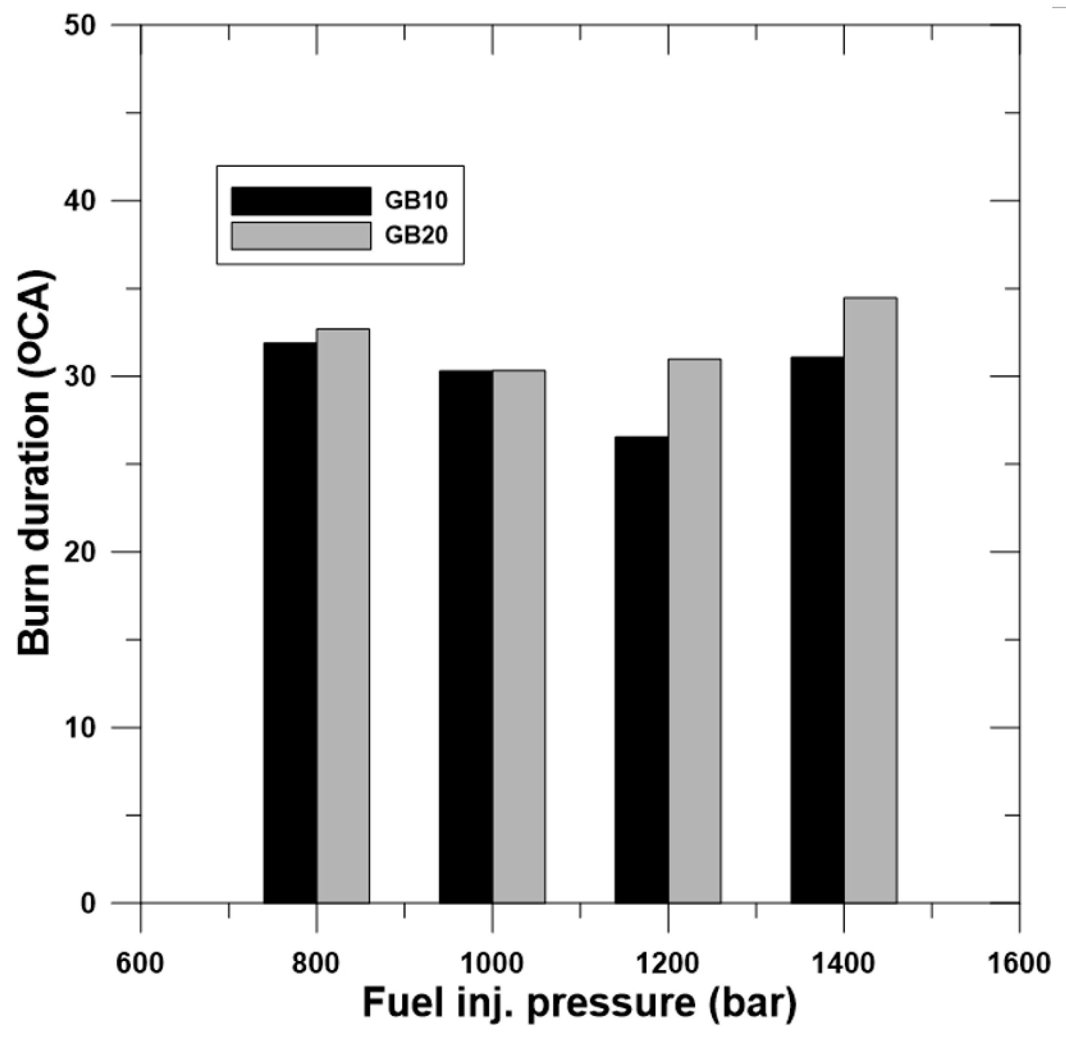
3.2.2. Combustion Duration and Ignition Delay

The ignition delay of the engine when operated using GB10 and GB20 fuels is presented in Figure 6. In this work, the ignition delay is defined as the time interval of fuel injected until combustion occurs. The second peak of the pressure rise rate is defined as the SOC, as described by Lee et al. [21]. Thus, it can be concluded that the ignition delay will be shortened when higher fuel injection pressure is applied in the engine. Increasing the content of biodiesel also affects the ignition process, making it occur faster. These phenomena are caused by the higher biodiesel content in GB20 than in GB10, which means GB20 has a higher cetane number. Generally, the cetane number is related to the autoignition characteristics of the fuel; the GB20 with its higher biodiesel content and higher cetane number will shorten the ignition delay. This is consistent with Adams [13]. A higher cetane number will also enhance the fuel capability to autoignite against compression, resulting in higher engine performance. Increasing the biodiesel content in a gasoline–biodiesel fuel mix will increase the cetane number, which will improve the autoignition speed and engine performance, as proposed by Putrasari et al. [3]. Meanwhile, an increase in fuel injection pressure increases cavitation—the main breakup—and, consequently, fuel atomization shortens the ignition delay as well as the duration of combustion.
Figure 7 shows the CA10, 50 and 90, while Figure 8 shows combustion duration of GB10 and GB20 with diferent fuel injection pressures. The combustion phasing can be observed in the CA10, CA50, and CA90 graphs. CA50 shows a very consistent advance when higher fuel injection pressure is applied. The start and the end of combustion can be observed from CA10 and CA90, respectively. The combustion duration of GB10 mostly has a lower burn duration than GB20. Fuel with a higher calorific value will produce a shorter total duration of combustion [22]. By increasing fuel injection pressure, shorter combustion duration due to smaller fuel droplets makes fuel more combustible. However, when the rate of increase in the first stage of heat release increases outside the main HRR, the duration of combustion shows an increase. When the first phase of the heat release phase is completed after TDC, the duration of combustion continues to decrease.

3.3. Brake Thermal Efficiency and BSFC

Figure 9 shows the brake thermal efficiency (BTE) of the engine using GB10 and GB20 with fuel injection pressures of 800 to 1400 bar. Both fuel blends showed the best improvement of BTE when the SOC occurred near TDC: 31.04% at 1000 bar for GB10 and 55.14% at 800 bar for GB20. Decreases in BTE were shown by both fuel mixes when the fuel injection pressure increased. Figure 10 shows the brake-specific fuel consumption (BSFC) of the engine using GB10 and GB20 with fuel injection pressures of 800 to 1400 bar. GB10 seemed to have a higher BSFC than GB20 in every experimental test: it had the highest fuel consumption, reaching 545 g/kWh at an 800-bar fuel injection pressure, compared to GB20’s 360 g/kWh at a 1400-bar fuel injection pressure.
Increasing the fuel injection pressure will increase the BSFC for all fuel blends. As discussed above, increasing the fuel injection pressure will decrease the ignition delay. A longer ignition delay gives the fuel a chance to mix with the air more perfectly, leading to better quality combustion. However, a too-long or too-short ignition delay will make the engine misfire, and a short ignition delay will produce low combustion quality and efficiency due to insufficient air–fuel mixing. The ignition timing and burn duration will also affect the efficiency of the combustion. However, a too-early SOC will produce backpressure, decreasing the piston speed before it reaches the TDC. A too-late SOC would lead to a decrease in efficiency because of volumetric effects and delayed fuel conversion processes. This statement is in agreement with Haris [23], who studied the effect of ignition delay (ID) on performance, emission, and combustion characteristics of 2-Methyl Furan-Unleaded gasoline blends. He found that retarded ignition will decrease in BTE. For GB10, the SOC at an 800-bar fuel injection pressure occurred after 4.6° ATDC, as shown in Figure 7, resulting in the lowest thermal and fuel efficiency compared with the other samples. The best efficiency was achieved when the SOC occurred synchronously with TDC, which for GB10 was 2.1° CA ATDC at a 1000-bar fuel injection pressure. For GB20, the closest SOC was achieved at an 800-bar fuel injection pressure, which was 2.6° CA BTDC. Meanwhile, by increasing the value of the cetane number, the efficiency also increased. Yakup [24] states that improvement in engine performance by increasing the cetane number may be attributed to improving the combustion process, as the reason for the highest efficiency is shown by GB20 in all tests.

4. Conclusions

This study of the combustion characteristics of two gasoline–biodiesel mixtures using various fuel injection pressures was conducted to gain more understanding of the effects of high fuel injection pressure in a GCI engine. The following conclusions can be drawn from the results of this study.
The injection rates for 600 and 1000 bar show a clear difference between GB10 and GB20, caused by the differences in density and viscosity between gasoline and biodiesel. GB10 results in higher injection rates than GB20 due to the higher content of biodiesel. However, a higher fuel injection pressure will deter the effects of density and viscosity differences on the fuel rate and injected fuel capacity.
If the SOC is closer to the TDC it will maximize combustion, so that it produces high in-cylinder pressure. However, when the SOC exceeds TDC, volumetric inefficiency will cause a pressure drop because GB10 at fuel injection pressures of 800 and 1000 bar has a lower in-cylinder pressure than GB20 while having a higher fuel heat value.
An increase in fuel injection will result in an increase in LTHR. Both fuel mixes showed a significant increase in fuel injection pressure above 1200 bar, which exceeded the main HRR and caused an increase of combustion duration. However, the duration of combustion will still decrease if the end of the first stage of heat release is complete after TDC.
The ignition delay decreased as the fuel injection pressure and the cetane content in the fuel increased. With both GB10 and GB20, increasing the fuel injection pressure above 800 bar produced low efficiency due to the shortened ignition delay. At a fuel injection pressure of 800 bar, GB10 produced the slowest ignition delay or SOC at 3.5° ATDC. At a fuel injection pressure of 1400 bar, GB20 produced the shortest ignition delay, leading to a retarded in-cylinder peak pressure which occurred at 0.24° BTDC, resulting in the lowest efficiency of both fuel mixes.
This study specifically studies the effects of applying high fuel injection pressure in GCI engines with gasoline as the main fuel on combustion characteristics. The idea of increasing efficiency by reducing fuel particles using high fuel injection pressure is not proven to increase efficiency in this system. Not only wasting power, high fuel pressure on gasoline will easily increase the fuel temperature due to fuel friction in the common rail. Fuel with high volatility, such as gasoline, requires a long ignition delay to increase combustion performance. However, further research needs to be done to find out the maximum ignition delay that can be applied to the GCI engine to produce optimal performance.

Author Contributions

Conceptualization, A.S.; methodology, A.S. and B.W.; softwere, A.S.; resource, A.S. and B.W.; writing original draft preparation, A.S.; writing review and editing, A.S.; O.L. supervised the research, advised on the research gap and objective, proofread the paper, and guided the writing process as well as reviewing the presented concepts and outcomes. All authors have read and agreed to the published version of the manuscript.

Acknowledgments

This research was financially supported by the Energy Technology Development Project of the Korea Energy Technology Evaluation and Planning (20182010106370, Demonstration Research Project of Clean Fuel DME Engine for Fine Dust Reduction), Republic of Korea.

Conflicts of Interest

The authors declare no conflict of interest.

References

  1. Kate, J.T.; Teunter, R.; Kusumastuti, R.D.; Van Donk, D.P. Bio-diesel production using mobile processing units: A case in Indonesia. Agric. Syst. 2017, 152, 121–130. [Google Scholar] [CrossRef]
  2. Biodiesel Statement. Available online: Volkswagen.co.uk (accessed on 4 August 2011).
  3. Putrasari, Y.; Lim, O. A study on combustion and emission of GCI engines fueled with gasoline-biodiesel blends. Fuel 2017, 189, 141–154. [Google Scholar] [CrossRef]
  4. Patel, H.K.; Kumar, S. Experimental analysis on performance of diesel engine using mixture of diesel and bio-diesel as a working fuel with aluminum oxide nanoparticle additive. Therm. Sci. Eng. Prog. 2017, 4, 252–258. [Google Scholar] [CrossRef]
  5. Badra, J.; Sim, J.; Elwardany, A.E.; Jaasim, M.; Viollet, Y.; Chang, J.; Amer, A.; Im, H.G. Numerical Simulations of Hollow-Cone Injection and Gasoline Compression Ignition Combustion with Naphtha Fuels. J. Energy Resour. Technol. 2016, 138, 052202. [Google Scholar] [CrossRef]
  6. Kodavasal, J.; Kolodziej, C.P.; Ciatti, S.; Som, S. Effects of injection parameters, boost, and swirl ratio on gasoline compression ignition operation at idle and low-load conditions. Int. J. Engine Res. 2016, 18, 824–836. [Google Scholar] [CrossRef]
  7. Ra, Y.; Loeper, P.; Reitz, R.D.; Andrie, M.; Krieger, R.; Foster, D.E.; Durrett, R.; Gopalakrishnan, V.; Plazas, A.; Peterson, R.; et al. Study of High Speed Gasoline Direct Injection Compression Ignition (GDICI) Engine Operation in the LTC Regime. Sae Int. J. Engines 2011, 4, 1412–1430. [Google Scholar] [CrossRef]
  8. Manente, V.; Zander, C.-G.; Johansson, B.; Tunestål, P.; Cannella, W. An Advanced Internal Combustion Engine Concept for Low Emissions and High Efficiency from Idle to Max Load Using Gasoline Partially Premixed Combustion. Sae Int. J. Engines 2010. [Google Scholar] [CrossRef]
  9. Zheng, M.; Han, X.; Asad, U.; Wang, J. Investigation of butanol-fuelled HCCI combustion on a high efficiency diesel engine. Energy Convers. Manag. 2015, 98, 215–224. [Google Scholar] [CrossRef]
  10. Hsieh, P.; Bruno, T.J. A perspective on the origin of lubricity in petroleum distillate motor fuels. Fuel Process. Technol. 2015, 129, 52–60. [Google Scholar] [CrossRef]
  11. Arkoudeas, P.; Karonis, D.; Zannikos, F.; Lois, E. Lubricity assessment of gasoline fuels. Fuel Process. Technol. 2014, 122, 107–119. [Google Scholar] [CrossRef]
  12. Misra, R.; Murthy, M. Blending of additives with biodiesels to improve the cold flow properties, combustion and emission performance in a compression ignition engine—A review. Renew. Sustain. Energy Rev. 2011, 15, 2413–2422. [Google Scholar] [CrossRef]
  13. Adams, C.A.; Loeper, P.; Krieger, R.; Andrie, M.; Foster, D.E. Effects of biodiesel–gasoline blends on gasoline direct-injection compression ignition (GCI) combustion. Fuel 2013, 111, 784–790. [Google Scholar] [CrossRef]
  14. El-Seesy, A.I.; Kosaka, H.; Hassan, H.; Sato, S. Combustion and emission characteristics of a common rail diesel engine and RCEM fueled by n-heptanol-diesel blends and carbon nanomaterial additives. Energy Convers. Manag. 2019, 196, 370–394. [Google Scholar] [CrossRef]
  15. Şen, M. The effect of the injection pressure on single cylinder diesel engine fueled with propanol–diesel blend. Fuel 2019, 254, 115617. [Google Scholar] [CrossRef]
  16. Agarwal, A.K. Biofuels (alcohols and biodiesel) applications as fuels for internal combustion engines. Prog. Energy Combust. Sci. 2007, 33, 233–271. [Google Scholar] [CrossRef]
  17. Goldsborough, S.S.; Hochgreb, S.; Vanhove, G.; Wooldridge, M.S.; Curran, H.J.; Sung, C.-J. Advances in rapid compression machine studies of low-and intermediate-temperature autoignition phenomena. Prog. Energy Combust. Sci. 2017, 63, 1–78. [Google Scholar] [CrossRef] [Green Version]
  18. Sung, C.-J.; Curran, H.J. Using rapid compression machines for chemical kinetics studies. Prog. Energy Combust. Sci. 2014, 44, 1–18. [Google Scholar] [CrossRef]
  19. Kim, J.; Lee, J.; Kim, K. Numerical study on the effects of fuel viscosity and density on the injection rate performance of a solenoid diesel injector based on AMESim. Fuel 2019, 256, 115912. [Google Scholar] [CrossRef]
  20. Raeie, N.; Emami, S.; Sadaghiyani, O.K. Effects of injection timing, before and after top dead center on the propulsion and power in a diesel engine. Propuls. Power Res. 2014, 3, 59–67. [Google Scholar] [CrossRef] [Green Version]
  21. Lee, S.; Song, S. A rapid compression machine study of hydrogen effects on the ignition delay times of n-butane at low-to-intermediate temperatures. Fuel 2020, 266, 116895. [Google Scholar] [CrossRef]
  22. Ashok, B.; Nanthagopal, K. Eco friendly biofuels for CI engine applications. In Advances in Eco-Fuels for a Sustainable Environment; Elsevier: Amsterdam, The Netherlands, 2019; pp. 407–440. [Google Scholar]
  23. Sivasubramanian, H. Effect of Ignition Delay (ID) on performance, emission and combustion characteristics of 2-Methyl Furan-Unleaded gasoline blends in a MPFI SI engine. Alex. Eng. J. 2018, 57, 499–507. [Google Scholar] [CrossRef]
  24. Içıngür, Y.; Altıparmak, D.; Altiparmak, D. Effect of fuel cetane number and injection pressure on a DI Diesel engine performance and emissions. Energy Convers. Manag. 2003, 44, 389–397. [Google Scholar] [CrossRef]
Figure 1. Rapid compression expansion (RCEM) engine setup.
Energies 13 03265 g001
Figure 2. Schematic diagram of the fuel injection test rate measurement system.
Energies 13 03265 g002
Figure 3. Fuel injection rates of GB10 and GB20.
Energies 13 03265 g003
Figure 4. (a) In-cylinder pressures of GB10 and (b) In-cylinder pressure of GB20.
Energies 13 03265 g004
Figure 5. Ignition delays of GB10 and GB20.
Energies 13 03265 g005
Figure 6. (a) Heat release rates of GB10 and (b) Heat release rate of GB20.
Energies 13 03265 g006
Figure 7. Combustion phasing of CA10, 50 and 90.
Energies 13 03265 g007
Figure 8. Burn duration.
Energies 13 03265 g008
Figure 9. Brake thermal efficiency.
Energies 13 03265 g009
Figure 10. Brake specific fuel consumption.
Energies 13 03265 g010
Table 1. The chemical composition of soybean oil [16].
Fatty AcidSystem NameFormulaStructureComposition (wt%)
Eruciccis-13-DocosenoicC22H42O222:10
BehenicDocosanoicC22H44O222:00
Linoleniccis-9, cis-12, cis-15-OctadecatrienoicC18H30O218:36
ArachidicEicosanoicC20H40O220:00
Oleiccis-9-OctadecenoicC18H34O218:123
StearicOctadecanoicC18H36O218:03
Linoleiccis-9, cis-12-OctadecadienoicC18H32O218:255
PalmiticHexadecanoicC16H32O216:012
LignocericTetracosanoicC24H48O224:00
MyristicTetradecanoicC14H28O214:00
Table 2. Physical properties of fuels [3].
Test ItemUnitTest MethodGasolineB100
Heating ValueMJ/kgASTM D240:200945.8639.79
Kinematic Viscosity (40 °C)mm2/sISO 3104:20080.7354.229
LubricitymmISO 12156–1:2012548189
Cloud Point°CISO 3015:2008−573
Pour Point°CASTM D6749:2002−571
Density (15 °C)kg/m3ISO 12185:2003712.7882.3

