Review

Towards Non-Mechanical Hybrid Hydrogen Compression for Decentralized Hydrogen Facilities

1
IJL, Université de Lorraine, CNRS, 88000 Epinal, France
2
LEMTA, Université de Lorraine, CNRS, F-54000 Nancy, France
*
Author to whom correspondence should be addressed.
Energies 2020, 13(12), 3145; https://doi.org/10.3390/en13123145
Submission received: 17 May 2020 / Revised: 11 June 2020 / Accepted: 15 June 2020 / Published: 17 June 2020
(This article belongs to the Special Issue Advances in Hydrogen Energy)

Abstract

:
The cost of the hydrogen value chain needs to be reduced to allow the widespread development of hydrogen applications. Mechanical compressors, widely used for compressing hydrogen to date, account for more than 50% of the CAPEX (capital expenditure) in a hydrogen refueling station. Moreover, mechanical compressors have several disadvantages, such as the presence of many moving parts, hydrogen embrittlement, and high consumption of energy. Non-mechanical hydrogen compressors have proven to be a valid alternative to mechanical compressors. Among these, electrochemical compressors allow isothermal, and therefore highly efficient, compression of hydrogen. On the other hand, adsorption-desorption compressors allow hydrogen to be compressed through cooling/heating cycles using highly microporous materials as hydrogen adsorbents. A non-mechanical hybrid hydrogen compressor, consisting of a first electrochemical stage followed by a second stage driven by adsorption-desorption of hydrogen on activated carbons, allows hydrogen to be produced at 70 MPa, a value currently required for the development of hydrogen automotive applications. This system has several advantages over mechanical compressors, such as the absence of moving parts and high compactness. Its use in decentralized hydrogen facilities, such as hydrogen refueling stations, can be considered.

Graphical Abstract

1. Introduction

According to the US Energy Information Administration, the breakdown of total world energy consumption by sector in 2018 was 33% for industry, 33% for transportation, 24% for the residential sector, and 10% for services [1]. In recent years, energy demand related to the transport sector has risen dramatically, from 26% in 2012 to 33% in 2018, and a further increase is expected. Globally, about 95% of vehicles currently use petroleum-based fuels, which partly explains the above-mentioned trend. Indeed, the demand for oil in industrialized countries, where the number of vehicles is growing exponentially every year, has increased from 56% to 72% during the last decade [2]. On the other hand, coal is expected to remain the predominant fuel for other energy applications, primarily power generation, for a long time to come. Nevertheless, the uncontrolled use of fossil fuels cannot continue indefinitely, due, at least, to environmental reasons and the need to fight climate change.
In addition, irreversible environmental issues will be inevitable if the global energy scenario continues to rely on fossil fuels for a long time. CO2 emissions have increased significantly in recent years, reaching 34 Mt per year, 40% higher than in 2010 [3]. The main consequence is the intensification of the greenhouse effect on our planet, and with it the increase in its average temperature. Indeed, Earth’s average temperature has increased by just over 1 K since 1880. Two thirds of global warming has occurred since 1975, at a rate of about 0.15–0.20 K per decade [4]. At this rate, global warming will be detrimental to ecosystems and human health, as infectious diseases will emerge due to the warmer and wetter environment.
For all the aforementioned reasons, the search for energy sources that could be both environmentally friendly and limitless is currently in great demand. The use of hydrogen as an energy vector fits perfectly into this framework, especially if it is produced from renewable sources. Indeed, hydrogen is a clean energy vector, and it is advocated as a serious candidate to replace fossil fuels, especially in the transport sector. Stationary hydrogen storage can also be envisaged as a guarantee of energy supply in the event of power grid failure or fluctuations in wind and solar energy. Indeed, the intermittency of renewable energy sources implies their storage in efficient and reactive storage systems, giving rise to the concept of smart grids. In this framework, power-to-hydrogen systems use expanding and inexhaustible renewable energy resources to power electrolyzers, producing hydrogen from water [5,6], thus reducing the load on the electricity grid and the risk of power outages [7]. Thus, electricity can be used to produce hydrogen by water electrolysis, and electrical energy can be produced by using hydrogen in fuel cell systems.
Since hydrogen is widely used in industry for the production of ammonia and the hydrogenation of petroleum products, the hydrogen sector, which includes production in decentralized facilities, storage and distribution, is already mature. However, the potential benefits of hydrogen as a fuel can be realized once storage methods are optimized and an efficient and safe distribution infrastructure is in place. In this context, the storage of hydrogen requires its compression. Mechanical compressors (piston, diaphragm, linear, and ionic liquid compressors), which are universally used for the compression of all gases, are not very suitable for the specific case of hydrogen. Research on new compression technologies, such as non-mechanical hydrogen compressors (metal hydrides, electrochemical, and adsorption-desorption compressors) is thus highly demanded, particularly with regard to the development of decentralized infrastructure for the production and use of hydrogen in situ.

2. Hydrogen as a Fuel

Hydrogen could play a key role in this critical scenario, as it could promote the development of new, innovative, and environmentally friendly solutions for energy use, which could lead to a transition towards divestment from fossil fuels [8]. Hydrogen has the highest gravimetric energy density among all non-nuclear fuels, i.e., 33 kWh kg−1 (based on the net calorific value). In comparison, the gravimetric energy density of gasoline is 13 kWh kg−1, which is three times less than that of hydrogen. Nevertheless, the density of hydrogen is very low and equal to 0.089 g L−1 at 298 K and 1 atm. This means that hydrogen exhibits the lowest volumetric energy density among the commonly used fuels, i.e., 0.003 kWh L−1 (compared to around 10 kWh L−1 for gasoline). Therefore, the realization of an efficient and practical hydrogen storage system is a significant challenge. Approximately 11,000 L would be required to store 1 kg of hydrogen or 33 kWh of energy. On the contrary, 1 kg of gasoline is stored in a volume of 1.3 L under the same conditions (considering a density of 775 g L−1), which is four orders of magnitude less than what is expected for hydrogen. Several ways of increasing the volumetric energy density of hydrogen are currently available, and will be discussed in the next section.
The only reaction product of hydrogen combustion in air is water, which is one of the most important advantages over fossil fuels in terms of environmental impact. The hydrogen diffusion coefficient in air, 0.62 cm2 g−1, is four times higher than that of natural gas. As a result, hydrogen dilutes very quickly in air, which is undoubtedly a safety advantage. Similarly, hydrogen flames are extinguished faster than those of gasoline or natural gas because hydrogen has a relatively high laminar flame velocity compared to other fuels (265–325 cm s−1). However, the flammable limits for the percentage by volume of hydrogen in air at atmospheric pressure are 4% and 75%. In addition, hydrogen–air mixtures can ignite with a very low energy input, of one-tenth that required to ignite a gasoline–air mixture.
Hydrogen is the most abundant element in the universe, but its exhaust velocity is so high that it is not retained in the Earth’s atmosphere. However, underwater exudations of natural hydrogen have recently been discovered, as well as the existence of geological structures from which large flows of natural hydrogen are released. Despite this, hydrogen used in the industrial sector is currently produced from fossil and renewable sources by various synthesis methods (Figure 1). The most widely used methods, based on mature technologies, are steam reforming of natural gas and partial oxidation of hydrocarbons. Nevertheless, these methods also produce large amounts of greenhouse gases and are therefore not environmentally friendly [9]. For this reason, methods for producing hydrogen from renewable sources have been developed in recent years, making a significant contribution to sustainable development. Among these, water electrolysis has proven to be a valid solution, since it allows the production of hydrogen from water [10]. Whenever electricity is available at low cost, water electrolysis is already used worldwide for industrial applications of a few MW. However, the production of hydrogen by water electrolysis costs about USD 4–8 kg−1 (for the specific case of polymer electrolyte membrane technology), which is around four times more expensive than the steam reforming method, i.e., USD 1.3 kg−1 [11]. Hydrogen production from biomass through supercritical water gasification and fermentation processes is also considered a sustainable alternative to hydrogen synthesis from fossil fuels [12,13]. However, the hydrogen production cost, about USD 3.5 kg−1 for a biomass price of USD 100 tons−1, is still too high to represent a real alternative to steam reforming [14]. Solar energy is also another sustainable and environmentally friendly way to produce hydrogen [15,16,17,18]. Solar-driven high-temperature steam electrolyzers were found to produce pure hydrogen with a rate of 1.2 g s−1, with an efficiency of around 25% [16]. Renewable hydrogen can also be generated by solar-driven water splitting. However, the search for stable and efficient photoelectrodes with reasonably higher photocurrent densities is required before commercialization [19].
According to statistics reported by the International Energy Agency, approximately 70 Mt of hydrogen are produced worldwide each year [20], of which 96% is produced from fossil fuels. The lowest cost of hydrogen production, USD 1.3 kg−1, is obtained by steam reforming of natural gas. This value is not significantly different from the production cost of liquid fuels used today, such as gasoline (the average global price of gasoline in May 2020 was USD 0.92 L−1 [21]). This low cost is due to the fact that 55% of the hydrogen is produced to synthesize ammonia in a very mature process that has been used for 100 years [22].
The biggest drawback of the hydrogen value chain is in the storage, transportation and distribution stages, which increase the price of hydrogen at the pump to USD 8–10 kg−1 [23]. Indeed, the hydrogen refueling station, including storage systems, can account for more than 75% of the final hydrogen pump price [24].

3. Hydrogen Storage for Automotive Applications

The low volumetric energy density of hydrogen is a critical feature in automotive applications. Indeed, hydrogen vehicles will have to represent a concrete alternative to conventional internal combustion engine vehicles to allow global commercialization. This means that at least 5 kg of hydrogen must be stored to cover a distance of 500 km; hence, only a tank volume of 61,000 L may allow this at 298 K and 1 atm. Nevertheless, technical solutions to reduce this huge volume exist, as discussed below.

3.1. Compressed Hydrogen Tanks

Compression is the most widely used methods to allow efficient storage of hydrogen, although it is not the cheapest approach [25]. The main effect of gas compression is to increase its density. Indeed, a density of 42.9 g L−1 is obtained by compressing hydrogen to 70 MPa and 298 K, which results in an increase in density of four orders of magnitude compared to the density at ambient conditions. Hence, 1 kg of hydrogen can be stored in a volume of approximately 23 L under the above-mentioned conditions. There are already hydrogen vehicles equipped with 70 MPa pressure tanks [26], which are capable of covering a distance of 500 km with 5 kg of hydrogen on board.
High-pressure hydrogen storage requires special tanks, which can both withstand hyperbaric conditions and prevent metal embrittlement by the hydrogen molecules. To this end, four different types of high-pressure tanks are currently used. The performance of a high-pressure tank is usually expressed by the performance index [27], i.e., the product pressure × volume × mass−1 (Figure 2). Type IV tanks are the most widely used to store hydrogen at very high pressure, as they ensure the best performance [28]. These tanks are made of carbon fiber, which reduces the weight of the storage system. Furthermore, a polymer inner lining prevents leakages. The cost of a type IV tank is around USD 14.75 kWh−1 when considering a manufacturing rate of 500,000 tanks per year [29]. On the contrary, types I and II are metal tanks and their use on-board is therefore difficult to envisage due to their high weight. Finally, type III tanks are made of composite materials, with an inner lining of aluminum, which makes them heavier than type IV tanks.
Although compression has proven to be an efficient solution for the storage of hydrogen, it has to be taken into account that it requires energy to take place. Therefore, 5% and 15% of the energy of hydrogen is consumed when it is compressed at 35 MPa and 70 MPa, respectively [30]. Thus, the amount of energy required increases with the pressure. This means that an energy cost equal to 5 kWh is required to compress 1 kg of hydrogen to 70 MPa, whereas the gravimetric energy density of hydrogen is 33 kWh at atmospheric pressure.

3.2. Liquid Hydrogen

The density of liquid hydrogen, i.e., 70.8 g L−1 at atmospheric pressure, is 40% higher than compressed gaseous hydrogen at 70 MPa, further reducing the size of the storage system. Indeed, 1 kg of liquid hydrogen is stored in a volume of 13.6 L, whereas it takes 23 L to store the same amount of gaseous hydrogen at 70 MPa. Nevertheless, special tanks are required to store liquid hydrogen at 20 K, as they must provide efficient thermal isolation to minimize losses due to hydrogen evaporation. Such losses are estimated to be about 1–5% per day [31]. Cryogenic tanks are made of an inner and outer lining, comprising an empty layer and several aluminum sheets alternated with glass fibers to prevent heat transfer, including radiation. Heat transfer within a cryogenic tank can also be minimized by increasing the volume-to-surface ratio, as in the case of spherical tanks. Evaporation of hydrogen causes an increase in pressure inside the cryogenic tank, and thus requires depressurization procedures by periodic evacuation. Therefore, additional hydrogen losses have to be taken into account [32].
Liquid hydrogen tanks can store approximately 8 kg of hydrogen in volumes of 120 L. However, the production of liquid hydrogen is quite expensive. Around 10 kWh kg−1 are required to liquefy hydrogen, i.e., 30% of the hydrogen chemical energy [33]. In addition, the capital expenditure (CAPEX) of industrial plants for hydrogen liquefaction is relatively high. A significant reduction in this cost could be achieved by increasing the production of liquid hydrogen from the current capacity of 5 tons per day to 150 tons per day [34] in the framework of centralized production.

3.3. Solid Storage in Metal Hydrides

Large hydrogen storage capacities, even higher than those generally obtained with compressed or liquefied hydrogen, can be achieved by absorption of hydrogen in metal hydrides. Indeed, up to 100 g of hydrogen per L can be stored in metal hydrides (in the specific case of MgH2), whereas 8.3 g per L and 70.8 g per L can be stored by compression at 15 MPa and liquefaction, respectively [35].
The storage of hydrogen in metal hydrides occurs by absorption, i.e., a volume phenomenon that involves the formation of chemical bonds between the hydrogen molecules and those of the substrate (chemisorption). Hydrogen storage capacities up to 7.6 wt.% have been obtained with Mg-based hydrides, e.g., MgH2 [36]. Furthermore, the kinetics of hydrogen absorption and desorption reactions in metal hydrides have been shown to be fully reversible [37]. Nevertheless, very high temperatures, even above 573 K, may be required to cause hydrogen desorption, which is one of the main disadvantages of hydrogen storage in metal hydrides [38]. The United States Department of Energy (DOE) has established that hydrogen storage capacities equal to or greater than 6.5 wt.% must be provided by a metal hydride system. This value takes into account both the weight of the storage material and that of the entire system, which comprises all supporting components and auxiliary systems. Hence, systems based on metal hydrides are unlikely to meet this target at present. Moreover, desorption temperatures between 333 and 393 K are demanded to consider the metal hydrides storage systems for commercialization [39]. Such a high desorption temperature is due to the high binding energy between the hydrogen and metal atoms, which can reach 60–100 kJ mol−1 [40]. In addition, absorption and desorption kinetics can be slow, with desorption times that can exceed 60 min (e.g., in the case of Mg-Al2O3) [36].
Intermetallic hydrides of the AB5 composition (with A = rare earth metal and B = Ni or Co) have shown excellent performance as reversible chemical storage media of hydrogen gas. Particularly attractive behaviors were found for LaNi5H6.7, as it is formed at pressures slightly above atmospheric pressure with a desorption temperature close to 293 K [41]. Nevertheless, the virtually achievable reversible hydrogen storage capacities of most intermetallic hydrides do not exceed 2 wt.% (1.5 wt.% for AB5 hydrides, 1.8 wt.% for AB2, and 2 wt.% for BCC alloys [41]). Since metal hydrides are relatively heavy, the weight ratio of stored hydrogen to the total storage system can be as low as 1–3% [42]. In addition, hydrogen absorption in metal hydrides is an exothermic phenomenon, which requires efficient cooling of the entire tank. Despite these latter drawbacks, hydrogen storage in metal hydrides remains particularly advantageous in terms of safety. Indeed, the hydrogen pressure inside a metal hydride tank is generally much lower than that reached in pressurized tanks, thus minimizing the risk of leaks [43]. For this reason, hydrogen storage in metal hydrides has proven to be an appropriate solution for short-distance vehicles such as scooters, golf carts, and electric bikes. Moderate quantities of hydrogen are required in this case, thus metal hydrides with low desorption temperature, such as the Ti-based hydrides (AB2-type) are a suitable solution [44]. Furthermore, metal hydride storage systems are very compact, making them even more suitable for short distances. For the storage of hydrogen on board fuel cell vehicles (FCV), “distributed hybrid hydrogen storage vessels” have recently been proposed, in which hydrogen is stored both in hydride materials and in pressurized tanks [45]. The hybrid concept benefits from both a higher storage capacity than its single metal hydrides counterpart and better thermal management. Moreover, it is more flexible and ensures a quick response to transient working conditions (such as acceleration or vehicle start-up).

3.4. Solid Storage in Microporous Materials

Hydrogen can interact with the surface of several microporous materials through weak Van der Waals forces, forming a monolayer. The interaction energies involved are very low, of the order of 0.01–0.1 eV [46], which means that no chemical bonds are generated between the hydrogen molecules and the surface of the microporous materials. This interaction is a completely reversible process, also known as “physisorption”. Several materials have been shown to have increased adsorption capacities, such as carbon-based materials (i.e., activated carbons, carbon nanotubes, and fullerenes), zeolites, metal organic frameworks (MOFs), and certain types of polymers [47,48,49,50,51]. Physisorption allows large hydrogen storage capacities to be reached. Indeed, it is generally assumed that the density of adsorbed hydrogen can be approximated to the density of liquid hydrogen, i.e., 70 g L−1, when the temperature is lowered to 77 K [52]. Hence, the use of adsorption on microporous materials instead of pure compression would give a volume gain of around 22% to the hydrogen storage system [53]. This advantage can be achieved in particular in the pressure range from 5 to 20 MPa [54].
The amount of hydrogen adsorbed on microporous materials is approximately proportional to their specific surface area, i.e., their micropore volume, but also depends on the size distribution and average width of the micropores [55]. A considerable hydrogen storage capacity of 9.9 wt.% at 77 K and 5.6 MPa has been measured for a MOF called NU-100 (Northwestern University 100) with a Brunauer, Emmett, and Teller (BET) area of 6143 m2 g−1 and a total pore volume of 2.82 cm3 g−1 [56]. This is one of the highest values ever achieved for hydrogen adsorption. It has also been shown that carbon adsorbents, especially activated carbons, have relatively high hydrogen adsorption capacities, on average 7 wt.% at 77 K and 4 MPa [57]. These values are higher than the gravimetric hydrogen storage recommended by the DOE for automotive applications, i.e., 5.5 wt.% by 2025 [39,58]. Nevertheless, not only the weight of the adsorbent but also the weight of the whole system must be taken into account. Moreover, the DOE recommends meeting such capacities in the temperature range of 233 to 358 K. This means that the DOE target remains difficult to achieve at room temperature, although hydrogen storage capacities can be improved by doping with metallic nanoparticles and heteroatoms [59,60,61].

4. The Hydrogen Value Chain

After being produced and before being used, hydrogen is packaged, distributed, stored, and delivered. The most complex issues requiring solutions are mainly related to these last two steps [62]. Indeed, the development of an efficient hydrogen supply chain has to take into account the energy lost between the source and the end user, in particular during transport and distribution. To date, there are two main ways to enable hydrogen distribution: centralized and decentralized (Figure 3).

4.1. Centralised Hydrogen Distribution

When hydrogen is produced in large industrial facilities, it can be compressed in situ and then distributed to users. In this scenario, hydrogen can be distributed in two ways: (i) through pipelines or (ii) stored in high-pressure tanks delivered by trucks.
Pipeline distribution of hydrogen is adopted primarily when hydrogen is produced in large industrial facilities from fossil fuels, for example, through the steam reforming of natural gas, which is the cheapest method for hydrogen production today and the most widely used when large quantities of hydrogen are required. Approximately 200,000 Nm3 h−1 are typically produced by an industrial facility for steam reforming of natural gas [63]. Recently, hydrogen has also been produced by electrolysis in industrial facilities located near power plants, resulting in a few hundreds of Nm3 h−1 of hydrogen [64]. To date, approximately 4500 km of pipelines are used to distribute hydrogen worldwide, half of which are in the United States (Figure 4) [65]. The installation of hydrogen pipelines requires a very high capital cost. Therefore, this solution has been proven only suitable for small to medium distances. In addition, the distribution of hydrogen through pipelines is undoubtedly less efficient than the distribution of methane. In order to compensate for pressure losses, the gas distributed through pipelines must be compressed at regular intervals. Thus, the energy required to compress the gas depends only on its volume and the pressure to be reached. Nevertheless, the energy recovered during the subsequent use of the gas is different. Indeed, 1 m3 of methane has an energy content of 9.89 kWh, whereas the same volume of hydrogen has 3 kWh. This means that the energy to be spent on hydrogen distribution through pipelines is three times higher than that spent on methane, for a desired amount of energy recovered [66].
Hydrogen can also be stored in high-pressure tanks delivered by trucks. In general, hydrogen is compressed to 25 MPa and then stored in tubes grouped in several packages. Normally, each group contains nine tubes, each with a volume of up to 2000 L [67]. This solution is particularly suitable when hydrogen has to be delivered to small hydrogen refueling stations, which are not served by the pipeline network. The tubes are usually made of metal; hence, they are type I high-pressure tanks (Figure 2). As mentioned earlier, very high pressures cannot be achieved using type I tanks. Therefore, the DOE’s goal is to produce large type III or type IV tanks, e.g., polymer tanks, to allow hydrogen storage at higher pressures, i.e., storage of larger quantities [68]. It has been shown that the cheapest way to store and deliver hydrogen is by compression and truck delivery, particularly for small hydrogen refueling stations and low demand [69]. However, transporting hydrogen is probably a dangerous solution. Although the probability of an accident is not greater than that of any other vehicle travelling on the same road, the risk of ignition of hydrogen-rich gas mixtures that may form near a leak remains an important issue to consider. Indeed, the minimum energy to ignite a stoichiometric hydrogen–air mixture is 0.02 mJ at 298 K and 1 atm. The presence of moving parts close to any leak can be a dangerous source of ignition. Despite this drawback, several safety measures are adopted to minimize the risk of ignition as much as possible. These include the use of a concrete liner to further reduce the risk of leakage.

4.2. Decentralized Facilities

A second scenario in the hydrogen value chain, which has attracted significant attention in recent years, is based on small and medium-sized facilities, where hydrogen is produced, stored, and distributed in situ at the same location. A good example is a hydrogen refueling station, designed to power a small number of fuel cell vehicles. Decentralized hydrogen production facilities typically supply a limited amount of hydrogen per day. Hydrogen can therefore be produced by electrolysis of water, resulting in production volumes of a few hundred Nm3 h−1. This is an important advantage since electricity is supplied to the hydrogen refueling stations, and water electrolysis is carried out directly on site. Indeed, electricity is much easier to transport than gas, thanks to the significant presence of high-voltage grids and distribution networks around the world. For instance, the high-voltage network in France covers a distance of more than 100,000 km, whereas the low and medium-voltage lines used for the distribution of electricity to users have a cumulative length of approximately 1.3 million kilometers [70].
For water electrolysis, three technologies are currently available: (i) alkaline water electrolysis (AEL); (ii) solid polymer electrolyte electrolysis (SPEL); and (iii) solid oxide electrolysis (SOEL). AEL uses concentrated liquid alkaline solutions of KOH or NaOH as electrolyte, and non-noble metals such as nickel as electrodes. Alternatively, SPEL relies on the use of proton or anion exchange membranes (PEMs/AEMs) as electrolyte, i.e., solid acids or lyes conducting protons or hydroxide ions, respectively. In PEM electrodes, only a catalyst based on the expensive platinum group can achieve good performance, whereas low-cost transition metal catalysts can be used for AEM electrolysis. Thus, both AEL and SPEL can operate between 323 and 353 K. On the other hand, SOEL uses ceramic materials as electrolyte and mixed ionic-electronic conductors (MIECs), such as A2MO4 oxides (A = rare earth, alkaline earth; M = transition metal), as electrodes. Despite several advantages, such as their flexibility and reversibility in electrolysis and fuel cell modes, this technology still faces some challenges to become economically competitive in the market. Indeed, SOEL operates at temperatures above 873 K, which promotes the degradation phenomena of the ceramic materials [71,72]. AEL has proved to be a key technology for large-scale hydrogen production powered by renewable energy [73]. The investment costs for AEL are from USD 800 to 1500 kW−1, whereas a higher cost between USD 1400 and 2100 kW−1 is necessary for the SPEL. Moreover, the lifetime of AEL is longer than that of SPEL (90,000 h vs. 20,000 h) [74]. Nevertheless, PEM water electrolysis is more efficient over a broader dynamic load range than AEL, especially due to the shorter start-up time and the lower footprint [74,75]. Thus, over the last five years, PEM systems with a power of several hundred kW or even MW have started to appear, corresponding to hydrogen production rates of around 10 to 20 kg h−1, [11]. In addition, high-pressure hydrogen can be produced by PEM water electrolysis with a high efficiency of about 70%. In fact, such a system allows the production of hydrogen at a pressure as high as 5 MPa, whereas AEL is limited to 3 MPa [76]. In the framework of automotive hydrogen applications, where hydrogen has to be compressed to 70 MPa anyway, this is an important advantage to reduce costs further. Water electrolyzers have been tested on a large scale, with a hydrogen production rate of 1 Nm3 h−1 and operating pressures up to 13 MPa [77,78]. Even though hydrogen can evolve at high pressure under isothermal conditions during water electrolysis, hydrogen permeation through the electrolyte increases with operating pressure, resulting in a loss of efficiency and safety risks [79].
In this context, hydrogen can only be defined as an environmentally friendly fuel if the electricity required for the operation of water electrolysis is produced by renewable sources, such as wind or solar energy (Figure 5). However, the potential benefits of this solution can only be realized after significant improvements in photovoltaic and wind power systems. The current price of hydrogen at the pump at a refueling station equipped with a renewable energy electrolyzer is approximately USD 17 kg−1 in Europe and USD 12.5 kg−1 in the United States [80,81]. This is significantly higher than the average pump price of gasoline, which is USD 2 kg−1 [82]. This large difference is mainly due to the cost of producing hydrogen. In the case of wind turbines, the cost of producing hydrogen by electrolysis can range from USD 8 kg−1 to USD 30 kg−1, depending on turbine and electrolyzer technology used [83]. Despite the high cost, several hydrogen refueling stations powered by renewable sources are already operational globally. In France, the FaHyence hydrogen refueling station produces about 40 kg of hydrogen per day, which can power 20–25 hydrogen vehicles daily [84].
In the case of decentralized facilities, the local hydrogen economy is generally penalized by higher investment costs, lower annual utilization rates, and higher electricity prices than in the case of centralized production [24], which explains why decentralized hydrogen refueling stations have not yet achieved economic profitability. Indeed, the total cost of a hydrogen refueling station can be as high as USD 3.2 million [85], which means that significant hydrogen production is required to recoup the investment. A reduction in the above cost can be achieved by increasing the efficiency of water electrolyzers, which is currently about 60% [74].

5. Hydrogen Compression

Hydrogen compression is a critical step in the hydrogen value chain. In the case of its centralized production by large industrial facilities, hydrogen is compressed close to the production site, i.e., before being distributed by pipelines or by tube trailers. On the other hand, when hydrogen is produced in situ in decentralized facilities, a compression system is placed downstream of the electrolyzer.
The use of large-scale technologies operating at high pressures allows hydrogen to be supplied at medium pressure, thus reducing both the compression work and the cost of compressing up to 70 MPa. As mentioned in Section 4.2, PEM water electrolysis has proved to be a key technology for the large-scale hydrogen production at medium pressures. Salt cavern storage is also another promising technology for high-pressure hydrogen storage due its low investment cost, high sealing potential, and low cushion gas requirement. Underground hydrogen storage is not significantly different from underground storage of natural gas. Thus, they are less susceptible to fire and have a relatively smaller surface facility than traditional storage tanks, which facilitates their integration in the landscape and existing infrastructure [86]. With a storage volume of 580,000 m3, the salt cavern of Clemens Dome (TN, USA) allows hydrogen storage up to 13.5 MPa, whereas the one in Moss Bluff (USA), with a storage volume of 566,000 m3, allows even higher pressures (15.2 MPa) [87]. In Europe, there are also suitable salt caverns that could be used for underground hydrogen storage, with a virtual storage volume of up to 750,000 m3 [88]. Despite the aforementioned advantages, geological, technological, economic, legal, and social obstacles have to be overcome before full-scale underground hydrogen storage can be implemented. Hence, the lower cost of hydrogen production through PEM water electrolysis will be the decisive factor for the implementation of this method of hydrogen storage on an industrial scale [86].
Hydrogen compression remains therefore a fundamental part of the hydrogen value chain at present. To date, mechanical compressors are the most widely used devices for compressing hydrogen. Mechanical hydrogen compressors rely on a very mature technology, and are used in particular when high flow rates of hydrogen have to be processed, in the order of thousands of Nm3 h−1 [89]. Several types of mechanical hydrogen compressors are available today. However, mechanical compressors have several drawbacks, making it necessary to look for alternative compression systems, which may be advantageous from both a technical and economic point of view.

5.1. Mechanical Hydrogen Compressors

Although mechanical compressors are widely used to drive the compression of several gases, they are not appropriate in the specific case of hydrogen. In addition, they do not yet meet the safety and reliability criteria necessary for their use, either in semi-industrial applications or at the level of the general public [90]. The main reason for this is that hydrogen tends to leak through the moving seals of mechanical compressors. This sealing problem inevitably implies a significant reduction in the potentially achievable efficiency. Moreover, hydrogen is easily absorbed by metals, causing embrittlement phenomena that can affect the mechanical performance of materials [91].
Mechanical compressors, such as reciprocating compressors, have several moving parts. Indeed, hydrogen compression is driven by the movement of several pistons, linked to a crankshaft, which, by means of a connecting rod, converts the linear movement of the pistons into a continuous rotational movement. Reciprocating compressors therefore have a high degree of structural complexity, which is undoubtedly a drawback. First of all, this involves a high maintenance cost, due to the presence of a high number of gears and valves, and the piston-crankshaft-connecting rod described above. The maintenance cost of mechanical compressors is estimated at 5% of the total investment cost per year [92]. In addition, lubricating oils have to be used to reduce any friction between the different moving parts, with the risk of hydrogen contamination [93]. Noise and vibration from moving parts must also be taken into account. Additionally, the latter is a problem for the environment of the compressor, especially in terms of workers’ health. Finally, reciprocating compressors are not a suitable choice when high compression ratios are demanded, e.g., to compress hydrogen from 0.1 to 10 MPa. This is because the size of the cylinders may be too large, preventing efficient cooling of the hydrogen during compression. This leads to an increase in the heat produced and makes it more difficult to manage the heat transfer [94].
Diaphragm compressors avoid the use of lubricating oils. In these devices, the hydrogen is completely isolated from the piston. Indeed, the movement of the piston is transmitted to a hydraulic fluid, which in turn transmits the movement to a thin membrane called a “diaphragm”, which isolates the compression chamber from the hydraulic part. Diaphragm compressors are particularly suitable for applications requiring low flow rates, because too high flow rates can lead to premature diaphragm failure, and also because of the limited volume of the compression chambers commonly used [95,96]. On the other hand, ionic liquid compressors have been specifically developed to increase the compression efficiency in the case of hydrogen. Ionic liquids can replace the solid piston for compressing hydrogen because of their intrinsically low vapor pressure, excellent tribological behavior, and negligible solubility of hydrogen in these liquids [97,98,99,100]. Ionic liquid compressors have been proven to be the best solution for the mechanical compression of hydrogen. These devices are capable of compressing hydrogen from 0.5 MPa to 100 MPa in only five steps and with a specific energy consumption of about 2.7 kWh kg−1, which is almost 25% of the specific energy consumption of a reciprocating compressor [101]. Moreover, ionic liquid compressors also have a very high efficiency of about 70% [102].
Although reciprocating compressors are most commonly used for hydrogen applications, centrifugal compressors are also an option. Indeed, a reciprocating compressor costs about 50% more than a centrifugal compressor [103]. The design of a centrifugal compressor is a multidimensional engineering task, since such a compressor is subject to a multitude of aerodynamic, thermodynamic, rotor dynamic, and mechanical parameters that are mutually interconnected and whose constraints largely determine the machine design [104]. Hydrogen centrifugal compressors consist of a succession of impellers that increase the hydrogen pressure. The case sections are then customarily connected in tandem to a common drive shaft [105]. Unlike reciprocating compressors, the compression ratio depends largely on the molecular weight of the gas in a centrifugal compressor. Indeed, the head of a centrifugal compressor is designed to increase the kinetic energy of the gas, which is then converted into pressure energy in the diffuser. Because of the low molecular weight of hydrogen, centrifugal compressors need tip-speeds that are around three times higher than those used for natural gas. Moreover, the aforementioned high-speed and purity requirements pose problems of seal design, contamination, vibration, and rotor dynamics [106]. Furthermore, because of its low specific gravity, hydrogen tends to return to the inlet, which reduces the efficiency of the centrifugal compressor. Thus, the impellers are easily subject to failure [107].
Although several types of mechanical devices for hydrogen compression exist and are available on the market, several of their disadvantages have to be taken into account. Beyond the drawbacks related to embrittlement phenomena mentioned above, contamination by lubricating oils, structural complexity, and maintenance difficulty, mechanical compressors normally consume between 5 and 15% of the energy stored by hydrogen. Additional problems arise when considering the installation of mechanical compressors in decentralized facilities, such as hydrogen refueling stations. This is because mechanical compressors are relatively large and can therefore take up a lot of space. Nevertheless, the major shortcoming of mechanical hydrogen compressors has to be addressed: their high cost. If hydrogen production is not taken into account, mechanical compression of hydrogen dominates the distribution of costs in a decentralized facility. Indeed, it is responsible for 54% of the CAPEX, 28% of the total energy consumption, and 18% of the operating and maintenance expenditure (OPEX) of a hydrogen refueling station [108]. Furthermore, the purchase price of a mechanical compressor is in the order of several hundred thousand dollars [109]. Therefore, the compression of a large amount of hydrogen must be carried out in order to amortize this cost.

5.2. Non-Mechanical Hydrogen Compressors

5.2.1. Metal Hydride Compressors

Non-mechanical hydrogen compressors have several advantages over mechanical compressors, including: (i) no moving components; (ii) quiet operation; (iii) high reliability and safety; and (iv) structural simplicity and greater compactness.
Of all non-mechanical hydrogen compressors, metal hydride compressors have attracted significant attention in recent years. They are thermally driven compressors because they use the properties of hydride-forming metals, alloys, or intermetallic compounds to absorb and desorb hydrogen simply by heat and mass transfer in the reaction system. Hydrogen absorption occurs at low temperature and lasts until the equilibrium pressure is equal to the feed pressure. When the metal hydride is heated, the hydrogen is desorbed and released at a higher pressure [110]. Metal hydride compressors are thoroughly described elsewhere [111]. No moving parts are present in a metal hydride compressor, which prevents the use of lubricating oils as needed in the case of mechanical compressors. However, this technology is limited both by the performance of the hydrides used and by heat management. Indeed, a multi-stage configuration is required to allow hydrogen compression up to 70 MPa [112]. This means that different types of metal hydrides have to be used in series, so that the desorption pressure of the first stage at high temperature can be slightly higher than the absorption pressure of the next stage at low temperature. In this way, the hydrogen is progressively compressed. Despite this, high desorption temperatures must be used in order to achieve high discharge pressures. To date, the average desorption temperature in metal hydride compressors is typically about 573 K, which significantly reduces efficiency by up to 10% [111]. Nevertheless, if the discharge pressure of a metal hydride compressor is sufficiently low, its cost may be lower than that of a mechanical hydrogen compressor operating at the same compression ratio [113].

5.2.2. Electrochemical Compressors

Based on the same principles as proton-exchange membrane fuel cells (PEMFCs), the electrochemical hydrogen compressor (EHC) has proven to be the most appropriate choice when hydrogen compression by a convenient, compact, cheap, and high-efficiency system is required [114]. Low-pressure hydrogen is fed to the anode of an electrochemical cell consisting of two electrodes, a polymer membrane, and gas diffusion layers. Here, the hydrogen is oxidized (Figure 6), thus splitting into protons and electrons, while electrical energy is supplied to the system. While the electrons follow the external electric circuit driven by a power supply, the protons pass through the polymer membrane to the cathode, where the hydrogen reduction reaction takes place. Hence, molecular hydrogen is produced there. The use of a backpressure regulator allows a flow of hydrogen at the desired discharge pressure. It is important to highlight that, unlike PEMFCs, the cathode of an EHC is blocked, i.e., no air is introduced. EHC requires very efficient core materials [115]. Nafion® is generally used as a membrane for EHCs [116]. Indeed, Nafion® offers high proton conductivity (0.13 S cm−1 at 348 K and 100% relative humidity), durability above 60,000 h, and high chemical stability [117]. Membrane-electrodes assemblies (MEA) are used to speed up the electrochemical process, in which metal nanoparticles, especially platinum, are dispersed in a solid electrolyte matrix in a similar way as PEMFCs, because of their excellent catalytic properties [118].
The compression mechanism described above is purely electrochemical, so that no moving unit is needed to drive it. This translates into a very high efficiency, up to 60% [119]. Furthermore, the EHC provides isothermal compression of hydrogen, which requires a lower energy demand compared to a polytropic or adiabatic process [120], and very high discharge pressures can be reached, even up to 100 MPa [121]. Despite all of these advantages, the efficiency of an EHC decreases considerably as the discharge pressure increases. Indeed, the permeation of molecular hydrogen through the PEM from cathode to anode increases linearly with the pressure difference over the EHC [122], reducing the amount of high-pressure hydrogen at the outlet of the EHC. This phenomenon is also known as “back-diffusion”. For this reason, the use of EHC was found to be more appropriate for low-pressure applications, such as power-to-gas or as a pump for hydrogen recirculation in fuel cell vehicles [123], as well as in high-pressure hybrid systems where the EHC performs a first pre-compression stage [124,125]. In addition, the EHC can also function as a purifying device, which is an important advantage when hydrogen is mixed with other gases, e.g., in H2-CH4 hythane mixtures [126]. Compared to other conventional means of hydrogen purification and compression, the EHC combines low energy cost, high H2 recovery and purity, low maintenance, low cost, and low operating temperature [127].

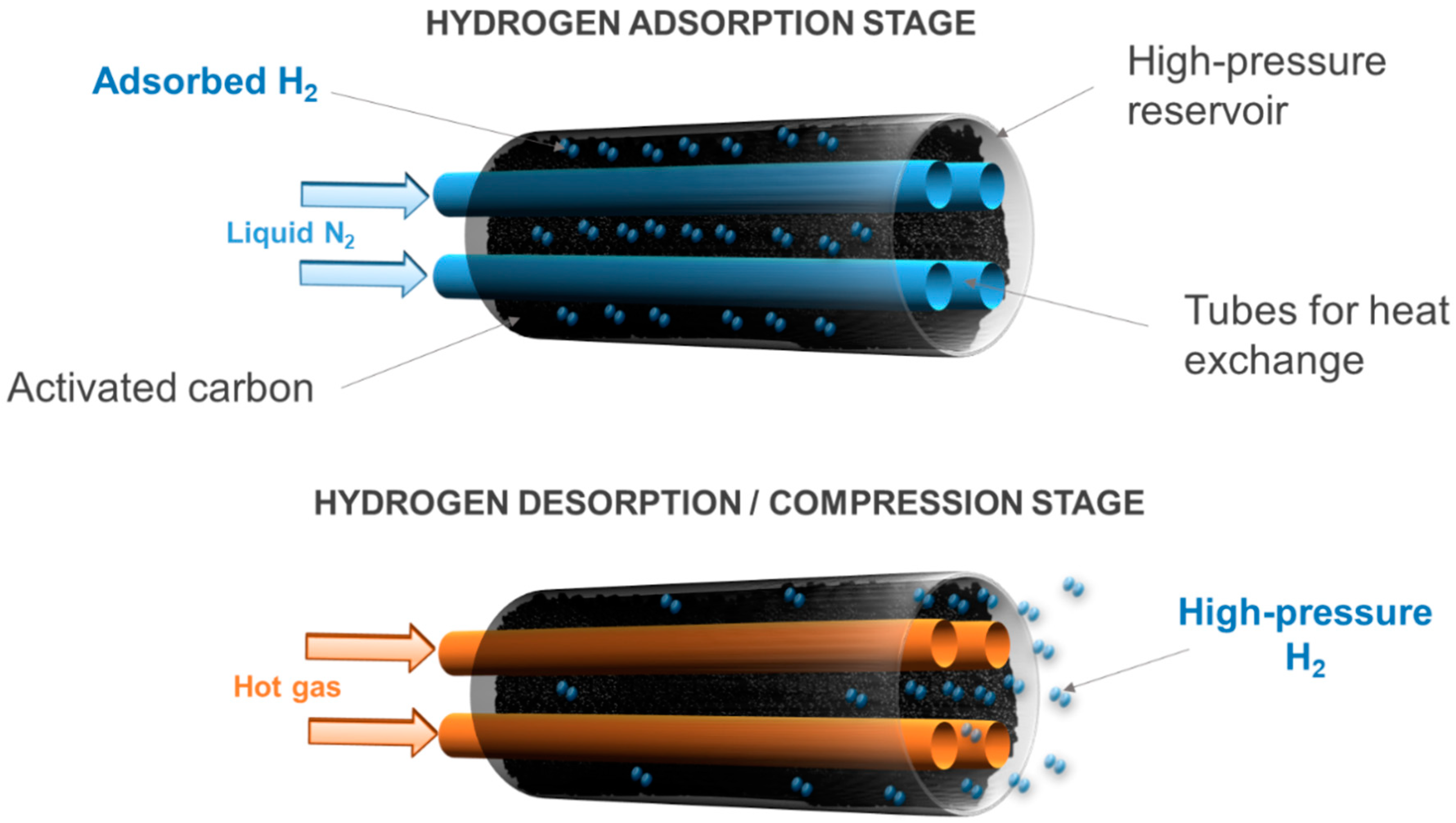
5.2.3. Adsorption–Desorption Compressors

The adsorption of hydrogen on nanotextured materials, thus having both a high specific surface area and microporosity, has been studied in depth in the context of hydrogen storage in solids, as shown in the previous sections. In addition, hydrogen physisorption on microporous materials can be exploited to drive hydrogen compression, which represents a new and innovative way of compressing hydrogen in a non-mechanical way, and is therefore worth exploring.
An adsorption–desorption compressor is a thermally driven compressor, just like metal hydride hydrogen compressors. Therefore, hydrogen compression comes from thermal cycles consisting of progressive cooling and heating stages. Hydrogen adsorption is initially carried out at cryogenic temperatures. Indeed, the density of adsorbed hydrogen increases considerably as the temperature of the system is lowered. It is generally assumed that the density of the adsorbed hydrogen can be approximated to the density of liquid hydrogen [128,129]. Some authors have even observed a behavior similar to that of solid hydrogen in the adsorbed phase [130]. Hence, hydrogen adsorption is generally carried out at 77 K, i.e., at the temperature of liquid nitrogen, which is easy to achieve from an industrial point of view. Under these conditions, the density of the adsorbed hydrogen is thus equal to 70.8 g L−1.
Hydrogen compression comes from the desorption of the pre-adsorbed amount of hydrogen. This is because hydrogen passes from the adsorbed phase, which is denser, to the bulk phase in a confined tank volume when the temperature rises. This can be done by removing the Dewar vessel filled with liquid nitrogen, where the compression tank is initially placed to drive the adsorption, thus leaving the tank at room temperature. Alternatively, a cooling system can be designed and placed inside the tank, in contact with the microporous adsorbent material, to manage better temperature gradients (Figure 7). In addition, microporous materials with high thermal conductivity should be used in order to increase the kinetics of adsorption and desorption. For instance, activated carbons, which have been shown to be well suited for hydrogen adsorption with their many advantages [47], have an average thermal conductivity of about 0.2 W m−1 K−1 [131], which may decrease the efficiency of the adsorption–desorption compressor. Nevertheless, the use of composite adsorbents, such as mixed powders of flexible graphite and activated carbon, can increase the effective thermal conductivity of the porous bed [132].
The adsorption–desorption compressor has all of the common advantages of non-mechanical compressors. Indeed, even if this technology is still too new to allow an accurate assessment of its performance and costs, the absence of moving parts undoubtedly contributes significantly to the reduction of installation and maintenance costs compared to mechanical compressors.

5.3. Overview of Costs and Efficiency

The US Department of Energy (DOE) has identified some targets to boost the widespread use of hydrogen compressors [133]. Specifically, referring to a device compressing hydrogen from 10 to 87.5 MPa, these targets are:
  • uninstalled cost of the compressor system: USD 275,000
  • specific energy consumption: 1.6 kWh kg−1
  • annual maintenance costs: 4% of the uninstalled costs.
The capital cost of a mechanical compressor averages USD 170,000 [134], whereas the OPEX is estimated at 5% of the capital cost per year [109]. While these costs are quite in line with DOE’s targets, the efficiency of a conventional mechanical hydrogen compressor is relatively low, around 45% [135]. Higher efficiencies (around 70%) can be obtained with an ionic liquid compressor. Indeed, such devices are able to compress hydrogen from 0.5 to 100 MPa in only five steps and a specific energy consumption of around 2.7 kWh kg−1—almost 25% of the specific energy consumption of conventional mechanical compressors [101].
There are several advantages of using a metal hydride compressor rather than a reciprocating compressor. According to a recent study on systems compressing hydrogen from 0.7 to 25 MPa [134], the CAPEX of a metal hydride compressor is around USD 150,000, compared to USD 170,000 for a reciprocating compressor operating under the same conditions. The OPEX value of a metal hydride compressor is estimated to be about USD 1000, compared to USD 9000 for a reciprocating compressor. In addition, the metal hydride compressor requires less electric energy to drive the compression of hydrogen, i.e., only 0.5 kW compared to the 20 kW of the reciprocating counterpart. There is also a significant advantage in terms of volume and weight (400 L and 100 kg for the metal hydride compressor; 6000 L and 3600 kg for the reciprocating compressor). Nevertheless, the specific energy consumption of a metal hydride compressor is relatively high due to the low thermal conductivity of the absorbent materials and the high heat of absorption. Indeed, around 10 kWh kg−1 may be required for a two-stage compression, lowering the compression efficiency to 10%.
The CAPEX of an electrochemical compressor can be as low as USD 170 per unit of hydrogen compression rate (kg day−1), compared to USD 2300 for the mechanical counterpart [114]. The OPEX of an electrochemical compressor is also estimated to be lower than that of a reciprocating compressor (<USD 1 kg−1 vs. USD 1.75–2.3 kg−1). The specific energy consumption of an electrochemical hydrogen compressor is, on average, less than 4 kWh kg−1, and strictly depends on the compression ratio. Indeed, electrochemical compressors have a high efficiency (>60%) and low energy consumption for low-pressure applications not exceeding 10 MPa [119].
Finally, the hydrogen adsorption–desorption compressor has been designed too recently to provide detailed information on CAPEX and OPEX, as well as on performance. The CAPEX is expected to be lower than that of a mechanical compressor, because of the significantly reduced number of moving parts and the more compact size. Nevertheless, the OPEX of an adsorption–desorption compressor can be quite high due to the wide operating temperature range and the use of liquid nitrogen, even though the heat of adsorption is 10 times lower than that of absorption in metal hydrides.
Table 1 and Table 2 summarize the main characteristics of mechanical and non-mechanical hydrogen compressors, respectively. A thorough description of current hydrogen compression technologies and performance is given elsewhere [94].

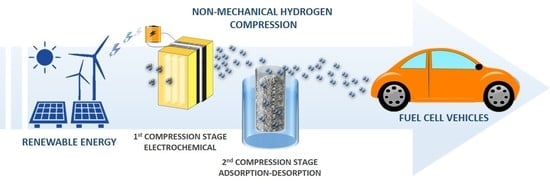
6. Non-Mechanical and Hybrid Hydrogen Compression in Decentralized Facilities

For the development of fuel cell vehicles, it is necessary that the amount of hydrogen to be stored on board should be sufficient to cover a distance of up to 500 km. For example, hydrogen must be compressed to 70 MPa in order to store 5 kg in 120 L, at least [136,137,138]. To date, the available non-mechanical hydrogen compression technologies are not capable of achieving such a value if used alone. Nevertheless, if a hybrid configuration is adopted, consisting of a preliminary first stage compressing the hydrogen up to medium pressures and a second stage completing the compression to 70 MPa, it is possible to realize a non-mechanical compression system that could be used in hydrogen refueling stations. Therefore, we investigated the feasibility of a hybrid hydrogen compression system comprising: (i) a first EHC stage, up to 4–8 MPa and (ii) an adsorption–desorption compressor that compresses hydrogen up to 70 MPa (Figure 8).
Figure 8 shows the proposed hybrid hydrogen-compression system without moving parts, as it is completely non-mechanical. It is also quiet in operation and has a simple structure and compact dimensions compared to mechanical hydrogen compressors. The performance of each stage of the aforementioned system is discussed below.

6.1. Performance of the Electrochemical Compressor

As mentioned in the previous sections, the EHC is a very compact device that allows hydrogen to be compressed with high efficiency. This is due to the fact that hydrogen compression in an EHC is isothermal, which requires less energy than polytropic or adiabatic compression. Nevertheless, high efficiencies can be only achieved if the discharge pressure is not too high, in order to prevent hydrogen back-diffusion. For this reason, the EHC represents a suitable solution in a hybrid hydrogen compressor if it is used as a first pre-compression stage up to medium pressures, e.g., 4–8 MPa.
One of the most important core materials of an EHC is the membrane, whose role is to drive the protons from the anode to the cathode. The membrane thickness has been found to play a key role in the performance of an EHC. Indeed, we have found that thin membranes, such as Nafion® XL (30 µm thick), perform better than thicker membranes, such as Nafion® 117 (175 µm). Indeed, at 333 K, for an applied current density of 0.33 A cm−2 and a discharge pressure of 4 MPa, Nafion® XL achieved an overall efficiency of 53%, compared to 37% obtained using Nafion® 117 under the same conditions [120]. This large difference is due to the cell voltage required to drive the electrochemical reactions. Indeed, a cell voltage of 0.137 V was supplied using Nafion® 117 under the aforementioned conditions, whereas around 0.06 V was supplied with Nafion® XL (Figure 9). These data are in agreement with those obtained by Grigoriev et al. [139], who proved that it is possible to compress hydrogen from 0.1 MPa to 4.8 MPa using a single-stage EHC, applying a cell voltage of 0.14 V and at 0.2 A cm−2, and using Nafion® 117 as the membrane. The aforementioned difference was obviously due to the higher ohmic resistance within the EHC, which resulted from the use of a thicker membrane, adding a significant overpotential contribution. It is important to underline that the detrimental contribution of the ohmic overpotential to the overall efficiency was much greater than that given by the hydrogen back-diffusion. Indeed, the hydrogen back-diffusion is inversely proportional to the membrane thickness [140]. An equivalent current density due to the back-diffusion equal to 5.22 mA cm−2 was obtained using Nafion® 117, whereas 45.31 mA cm−2 (i.e., nine times more) was obtained in the case of Nafion® XL.
Although EHC is based on the same technology and core materials as PEMFCs, some changes must be anticipated. This is the case for gas diffusion layers. While in PEMFCs carbon papers are recognized globally for the efficient transport of reagents and products into and out of the system [141], they are not able to withstand the large pressure gradients on the EHC. Therefore, porous titanium transfer layers, with a small average pore size (3–5 µm) and a high thickness (of the order of millimeters), can be used.
The rate of production of high-pressure hydrogen in an EHC, n ˙ H 2 , (NL h−1), only depends on the global current density supplied to the system, I (A cm−2), and the amount of energy lost due to back-diffusion, Iloss (A cm−2), according to Faraday’s law:
n ˙ H 2 = ( I I l o s s )   S 2 F
where S (cm−2) is the active area of the EHC and F (96,485 C mol−1) is the Faraday constant. According to Equation (1), n ˙ H 2 is about 15.6 NL h−1 at 1 A cm−2, and increases linearly to 31.2 and 46.98 NL h−1 at 2 and 3 A cm−2, respectively. In addition, the choice of the most appropriate I to be applied to the EHC is essential for practical applications. Indeed, the obvious advantage of supplying a high I to the EHC lies in its greater compactness and lower CAPEX, as well as in the higher rate of production of high-pressure hydrogen. Nevertheless, OPEX is relatively high under these conditions, and it can only be significantly reduced by decreasing I. Therefore, an I in the range of 0.5 to 1 A cm−2 is commonly used in an EHC compressor, such as in PEM water electrolyzers and PEMFCs [139].
In order to improve the performance of an EHC, efficient water management inside the device must be ensured. Indeed, the transfer of protons from the anode to the cathode of the EHC, i.e., the ionic conductivity of the Nafion® membrane, is only enhanced if the membrane is well hydrated homogenously. Unlike PEMFCs, water is not a reaction product in the EHC. Therefore, water is generally fed along with hydrogen into the anode compartment of the EHC. Unreacted hydrogen can also be recirculated from the anode outlet to the anode inlet to improve system efficiency, after rewetting and when high hydrogen stoichiometry is used. Liquid water can also be fed to the cathode side, which allows a better humidification of the membrane. Both of the aforementioned solutions are particularly appropriate when the anode pressure is above 0.1 MPa, i.e., when the molar fraction of water at the anode inlet is significantly lower than that of hydrogen. Nevertheless, a low-pressure pump for hydrogen recirculation and a high-pressure pump for feeding water to the high-pressure compartment shall be added to the system, resulting in an additional OPEX. It has been proved that a relative humidity of 90% in the hydrogen flow fed to the EHC allows a homogenous humidification of the membrane, which results in a stable and enhanced performance and high efficiency. Indeed, when hydrogen at low relative humidity is fed to the EHC, i.e., <30%, unstable performance is observed. The EHC acts in such a way as to “consume” water on the cathode side, leading to a progressive dehydration of the membrane and, consequently, a significant reduction in efficiency [120]. Since water is used to humidify the EHC membrane, the high-pressure hydrogen flow produced at the cathode is wet. Thus, a desiccant must be used downstream of the EHC to dry the compressed hydrogen that will be fed into the next compression stage, i.e., the adsorption–desorption compressor (Figure 8).

6.2. Performance of the Adsorption–Desorption Compressor

Several materials can be used in the adsorption–desorption compression of hydrogen, provided they have both a high specific surface area and adequate pore size distribution. Indeed, it is essential that the adsorbent material have a high hydrogen adsorption capacity in order to produce large amounts of high-pressure hydrogen. Of all of the microporous adsorbent materials investigated in recent years for hydrogen adsorption, it has been shown that metal organic frameworks (MOFs) have outstanding BET (Brunauer, Emmett and Teller) areas, even higher than 6000 m2 g−1, capable of adsorbing up to 10 wt.% of hydrogen at 77 K and 6 MPa [48]. Likewise, hyper-crosslinked polymers, silicas, aluminas, and zeolites have also shown high hydrogen adsorption capacities [49,51,142,143]. Nevertheless, most of these materials are relatively expensive, and their properties gradually degrade with ageing. Therefore, carbon materials, e.g., activated carbons, have proven to be the most suitable adsorbent materials for an adsorption–desorption compressor due to their moderate cost, high chemical stability, and textural properties suitable for hydrogen adsorption [47,144].
Beyond the absence of any moving part, one of the main advantages of an adsorption–desorption compressor is the ability to control the hydrogen discharge pressure by both the charging pressure and the desorption temperature. Indeed, numerical simulations have shown that it is possible to compress hydrogen up to 70 MPa by heating an adsorption–desorption compressor from 77 to 298 K and when hydrogen is fed at 4 MPa [145]. At a charging pressure of 0.1 MPa, a discharge pressure of 12 MPa was reached, which is not sufficient for automotive hydrogen applications [146]. This feature highlights the need for a first preliminary compression stage upstream of an adsorption–desorption compressor, as discussed above. Improvements are possible by increasing the desorption temperature. Indeed, it was shown that the amount of desorbed hydrogen can increase from 5% to 14% of the total amount of pre-adsorbed hydrogen when the system is heated further from 298 to 353 K [145], which considerably increases the amount of high-pressure hydrogen produced by the compressor. Temperatures above 298 K can be reached by using the heat recovered from the first compression stage. It is worth mentioning that a high-pressure water electrolyzer may also be used as a preliminary stage of the adsorption–desorption compressor. These devices typically operate at 353 K [10], so that the waste heat from the electrolyzer may be used to heat the adsorption–desorption compressor, thus improving the overall system efficiency.
The adsorption–desorption compressor is almost entirely controlled by heat exchange with the external environment. Figure 10a shows the time evolution of pressure and temperature that we obtained when using a 0.5 L adsorption–desorption compressor filled with 0.175 kg of commercially activated carbon (MSP20X, Kansai Coke&Chemicals, Hyogo, Japan). The increase in hydrogen pressure inside the tank was strictly related to the increase in temperature. Thus, the ambient temperature and the highest discharge pressure of 65 MPa were reached in 80 min. The time evolution shown in Figure 10 was obtained by heating the compressor by natural convection, i.e., by removing it from liquid nitrogen and keeping it at ambient temperature. It should be mentioned that we have only focused on a proof of concept in this study, so we did not evaluate the energy performance of such a thermally driven adsorption-desorption compressor. Indeed, an industrial system must have internal heat exchangers to optimize heat transfer, as shown in Figure 7. Methods to further reduce energy consumption, increase efficiency, and reduce the duration of the compression stage may include the use of cheap waste heat as previously stated, but also the cold recovery.
The data shown in Figure 10a were obtained by feeding hydrogen at 8 MPa into the adsorption–desorption compressor. Indeed, the activated carbon used has a very low bulk density (350 g L−1), which limits the available specific surface area and micropore volume for hydrogen adsorption in the tank. Therefore, increasing the hydrogen charging pressure was found to be a good solution to increase the amount of hydrogen adsorbed in the compressor [125]. Nevertheless, the discharge pressure reached under these conditions was 65 MPa, slightly lower than that required by hydrogen automotive applications. For this reason, either increasing the charging pressure to 9 MPa or increasing the desorption temperature above 298 K could allow 70 MPa to be reached. By adopting the second solution, thus increasing the desorption temperature to 323 K, a high-pressure hydrogen flow was produced by the compressor, as shown in Figure 10b. Approximately 32 NL h−1 were quickly released by the compressor once the pressure inside the tank was 70 MPa, and a decreasing flow was then obtained for about 60 min. The high-pressure hydrogen flow vanished when the pressure inside the tank was below 70 MPa. The ratio of the total mass of high-pressure hydrogen produced to the tank volume was then equal to approximately 1 g L−1 for these non-optimized conditions.
In order to make this system a feasible alternative to mechanical compressors or other types of non-mechanical compressors, several improvements are necessary. Mixtures of graphite-activated carbons could be used to increase the effective thermal conductivity of the porous bed, while a densification processes could be used to increase the bulk density of the adsorbent [147,148]. Such methods would increase the amount of hydrogen adsorbed within the porous bed and, with it, the mass of compressed hydrogen.
The energy optimization of the proposed adsorption–desorption compression is in progress. Thus, a system consisting of two tanks operating with a 180° phase shift is being studied. Indeed, the specific energy required by this system can be improved by using the frigories of the first tank during heating to cool the second tank. In this way, a thermally driven compressor could become a valid alternative to mechanical compressors from an industrial point of view.

7. Conclusions

Reducing the cost of hydrogen storage is crucial for the development of automotive hydrogen applications, such as fuel cell vehicles. In fact, the storage, transportation, and distribution stages cause significant increases in the price of hydrogen at the pump, which is currently at USD 8–10 kg−1.
High-pressure hydrogen storage has been proven to be the most suitable method for storing hydrogen in decentralized facilities, i.e., at hydrogen refueling stations, compared to liquid-phase storage and storage in absorbed form in solid materials. Nevertheless, mechanical compressors, which are the most widely used technology for compressing hydrogen today, are responsible for more than 50% of CAPEX, 20% of OPEX, and about 30% of the total energy consumption of a hydrogen refueling station. Furthermore, mechanical compressors have several disadvantages, such as the presence of many moving parts, hydrogen embrittlement, high consumption of energy, high structural complexity, and difficult heat management.
Non-mechanical compressors, such as metal hydride, electrochemical, and adsorption–desorption compressors, may be a suitable alternative to replace mechanical compressors in decentralized facilities. Indeed, they have several advantages, such as the absence of moving parts that contributes significantly to the reduction of installation and maintenance costs compared to mechanical compressors. Metal hydride compressors ensure both safe storage and compression of hydrogen. As they require heat exchange, they are also known as thermally driven compressors. The search for appropriate alloys is essential for the development of such technology, as it requires both low desorption temperatures and high pressures.
Electrochemical compressors are based on the use of selective polymeric membranes, such as Nafion®, to compress hydrogen gas, and have been proven to provide the highest level of compression efficiency (up to 60%) when the discharge pressure is not too high. Indeed, the efficiency of such devices is affected by the hydrogen back-diffusion. Electrochemical compressors have been found to offer good performances when equipped with a thin membrane at 1 A cm−2.
Adsorption–desorption compressors rely on the ability of hydrogen to bind weakly to the surface of highly porous solids, such as carbon materials or metal-organic frameworks. Like metal hydride compressors, adsorption–desorption compressors are also thermally driven. Nevertheless, operation at a cryogenic temperature, down to 77 K, is required to enhance hydrogen uptakes. Such devices are able to compress hydrogen up to 70 MPa in a single step.
Hybrid configurations, consisting of: (i) a first electrochemical stage up to 4–8 MPa; and (ii) a second stage based on cyclic adsorption–desorption on carbon materials, make it possible to reach 70 MPa in a compact and quiet device. This could represent a promising alternative to mechanical hydrogen compressors in the framework of decentralized facilities, such as hydrogen refueling stations.

Author Contributions

Writing—original draft preparation, G.S.; writing—review and editing, project administration and funding acquisition, G.M.; writing—review and editing, A.C.; Conceptualization, writing—review and editing, project administration and funding acquisition, V.F. All authors have read and agreed to the published version of the manuscript.

Funding

This study was partly supported by the French PIA project “Lorraine Université d’Excellence”, reference ANR-15-IDEX-04-LUE. We gratefully acknowledge the financial support of CHEERS and TALiSMAN projects, funded by FEDER.

Conflicts of Interest

The authors declare no conflict of interest.

References

  1. International Energy Agency. World Energy Balances 2019—Analysis. Available online: https://www.iea.org/reports/world-energy-balances-2019 (accessed on 2 May 2020).
  2. Dunn, S. Hydrogen futures: Toward a sustainable energy system. Int. J. Hydrog. Energy 2002, 27, 235–264. [Google Scholar] [CrossRef]
  3. International Energy Agency. CO2 Emissions Statistics—Data Services. Available online: https://www.iea.org/subscribe-to-data-services/co2-emissions-statistics (accessed on 2 May 2020).
  4. NASA. Global Climate World of Change: Global Temperatures. Available online: https://earthobservatory.nasa.gov/world-of-change/global-temperatures (accessed on 2 May 2020).
  5. Thema, M.; Bauer, F.; Sterner, M. Power-to-Gas: Electrolysis and methanation status review. Renew. Sustain. Energy Rev. 2019, 112, 775–787. [Google Scholar] [CrossRef]
  6. Mazza, A.; Bompard, E.; Chicco, G. Applications of power to gas technologies in emerging electrical systems. Renew. Sustain. Energy Rev. 2018, 92, 794–806. [Google Scholar] [CrossRef]
  7. Gondal, I.A. Hydrogen integration in power-to-gas networks. Int. J. Hydrog. Energy 2019, 44, 1803–1815. [Google Scholar] [CrossRef]
  8. Hall, C.A.S.; Lambert, J.G.; Balogh, S.B. EROI of different fuels and the implications for society. Energy Policy 2014, 64, 141–152. [Google Scholar] [CrossRef] [Green Version]
  9. Nikolaidis, P.; Poullikkas, A. A comparative overview of hydrogen production processes. Renew. Sustain. Energy Rev. 2017, 67, 597–611. [Google Scholar] [CrossRef]
  10. Parra-Restrepo, J.; Bligny, R.; Dillet, J.; Didierjean, S.; Stemmelen, D.; Moyne, C.; Degiovanni, A.; Maranzana, G. Influence of the porous transport layer properties on the mass and charge transfer in a segmented PEM electrolyzer. Int. J. Hydrog. Energy 2020, 45, 8094–8106. [Google Scholar] [CrossRef]
  11. Babic, U.; Suermann, M.; Büchi, F.N.; Gubler, L.; Schmidt, T.J. Critical Review—Identifying Critical Gaps for Polymer Electrolyte Water Electrolysis Development. J. Electrochem. Soc. 2017, 164, F387–F399. [Google Scholar] [CrossRef] [Green Version]
  12. Hosseini, S.E.; Wahid, M.A. Hydrogen production from renewable and sustainable energy resources: Promising green energy carrier for clean development. Renew. Sustain. Energy Rev. 2016, 57, 850–866. [Google Scholar] [CrossRef]
  13. Ausiello, A.; Micoli, L.; Turco, M.; Toscano, G.; Florio, C.; Pirozzi, D. Biohydrogen production by dark fermentation of Arundo donax using a new methodology for selection of H2-producing bacteria. Int. J. Hydrog. Energy 2017, 42, 30599–30612. [Google Scholar] [CrossRef]
  14. Salkuyeh, Y.K.; Saville, B.A.; MacLean, H.L. Techno-economic analysis and life cycle assessment of hydrogen production from different biomass gasification processes. Int. J. Hydrog. Energy 2018, 43, 9514–9528. [Google Scholar] [CrossRef]
  15. Hosseini, S.E.; Wahid, M.A. Hydrogen from solar energy, a clean energy carrier from a sustainable source of energy. Int. J. Energy Res. 2020, 44, 4110–4131. [Google Scholar] [CrossRef]
  16. He, W.; Namar, M.M.; Li, Z.; Maleki, A.; Tlili, I.; Safdari Shadloo, M. Thermodynamic analysis of a solar-driven high-temperature steam electrolyzer for clean hydrogen production. Appl. Therm. Eng. 2020, 172, 115152. [Google Scholar] [CrossRef]
  17. Karapekmez, A.; Dincer, I. Thermodynamic analysis of a novel solar and geothermal based combined energy system for hydrogen production. Int. J. Hydrog. Energy 2020, 45, 5608–5628. [Google Scholar] [CrossRef]
  18. Barbir, F. PEM electrolysis for production of hydrogen from renewable energy sources. Sol. Energy 2005, 78, 661–669. [Google Scholar] [CrossRef]
  19. Ahmed, M.; Dincer, I. A review on photoelectrochemical hydrogen production systems: Challenges and future directions. Int. J. Hydrog. Energy 2019, 44, 2474–2507. [Google Scholar] [CrossRef]
  20. International Energy Agency. Hydrogen—Tracking Energy Integration—Analysis. Available online: https://www.iea.org/reports/tracking-energy-integration/hydrogen (accessed on 2 June 2020).
  21. GlobalPetrolPrices.com. Gasoline Prices around the World. Available online: https://www.globalpetrolprices.com/gasoline_prices/ (accessed on 2 June 2020).
  22. Hydrogen Europe. Hydrogen in Industry. Available online: https://hydrogeneurope.eu/hydrogen-industry (accessed on 2 June 2020).
  23. Harvey, L.D.D. Energy and the New Reality 2: Carbon-free Energy Supply; Earthscan: New York, NY, USA, 2010; ISBN 978-1-84407-913-1. [Google Scholar]
  24. Commissariat de l’énergie atomique. L’hydrogène, les nouvelles technologies de l’énergie. Clefs CEA 2004, 50, 6. [Google Scholar]
  25. Amos, W.A. Costs of Storing and Transporting Hydrogen; National Renewable Energy Lab.: Golden, CO, USA, 1999.
  26. La Toyota. Mirai est la Voiture de Demain. Available online: https://www.toyota.fr/new-cars/new-mirai/landing.json (accessed on 15 April 2019).
  27. Krawczak, P. Réservoirs Haute Pression en Composites. Available online: https://www.techniques-ingenieur.fr/base-documentaire/materiaux-th11/applications-des-composites-42140210/reservoirs-haute-pression-en-composites-am5530/ (accessed on 17 June 2019).
  28. Moradi, R.; Groth, K.M. Hydrogen storage and delivery: Review of the state of the art technologies and risk and reliability analysis. Int. J. Hydrog. Energy 2019. [Google Scholar] [CrossRef]
  29. James, B.D.; Houchins, C.; Huya-Kouadio, J.; DeSantis, D.A. Final Report: Hydrogen Storage System Cost Analysis; Strategic Analysis Inc.: Arlington, VA, USA, 2016. [Google Scholar]
  30. Fraser, D. Solutions for hydrogen storage and distribution. In Proceedings of the PEI Wind-Hydrogen Symposium, Charlottetown, PE, Canada, 22–24 June 2003. [Google Scholar]
  31. Michel, F.; Fieseler, H.; Allidières, L. Liquid hydrogen technologies for mobile use. In Proceedings of the World Hydrogen Energy Conference WHEC, Lyon, France, 13–16 June 2006. [Google Scholar]
  32. Liu, Z.; Li, Y. Thermal physical performance in liquid hydrogen tank under constant wall temperature. Renew. Energy 2019, 130, 601–612. [Google Scholar] [CrossRef]
  33. Sørensen, B.; Spazzafumo, G. 2—Hydrogen. In Hydrogen and Fuel Cells, 3rd ed.; Sørensen, B., Spazzafumo, G., Eds.; Academic Press: Cambridge, MA, USA, 2018; pp. 5–105. ISBN 978-0-08-100708-2. [Google Scholar]
  34. Cardella, U.; Decker, L.; Klein, H. Roadmap to economically viable hydrogen liquefaction. Int. J. Hydrog. Energy 2017, 42, 13329–13338. [Google Scholar] [CrossRef]
  35. Selvam, P.; Viswanathan, B.; Swamy, C.S.; Srinivasan, V. Magnesium and magnesium alloy hydrides. Int. J. Hydrog. Energy 1986, 11, 169–192. [Google Scholar] [CrossRef]
  36. Sakintuna, B.; Lamari-Darkrim, F.; Hirscher, M. Metal hydride materials for solid hydrogen storage: A review. Int. J. Hydrog. Energy 2007, 32, 1121–1140. [Google Scholar] [CrossRef]
  37. Alapati, S.V.; Johnson, J.K.; Sholl, D.S. Using first principles calculations to identify new destabilized metal hydride reactions for reversible hydrogen storage. Phys. Chem. Chem. Phys. 2007, 9, 1438–1452. [Google Scholar] [CrossRef] [PubMed]
  38. Jain, I.P.; Lal, C.; Jain, A. Hydrogen storage in Mg: A most promising material. Int. J. Hydrog. Energy 2010, 35, 5133–5144. [Google Scholar] [CrossRef]
  39. Department of Energy. Technical Targets for Onboard Hydrogen Storage for Light-Duty Vehicles. Available online: https://energy.gov/eere/fuelcells/doe-technical-targets-onboard-hydrogen-storage-light-duty-vehicles (accessed on 28 February 2017).
  40. Satyapal, S.; Petrovic, J.; Read, C.; Thomas, G.; Ordaz, G. The U.S. Department of Energy’s National Hydrogen Storage Project: Progress towards meeting hydrogen-powered vehicle requirements. Catal. Today 2007, 120, 246–256. [Google Scholar] [CrossRef] [Green Version]
  41. Hirscher, M.; Yartys, V.A.; Baricco, M.; Bellosta von Colbe, J.; Blanchard, D.; Bowman, R.C.; Broom, D.P.; Buckley, C.E.; Chang, F.; Chen, P.; et al. Materials for hydrogen-based energy storage—Past, recent progress and future outlook. J. Alloys Compd. 2020, 827, 153548. [Google Scholar] [CrossRef]
  42. Sheffield, J.W.; Martin, K.B.; Folkson, R. 5—Electricity and hydrogen as energy vectors for transportation vehicles. In Alternative Fuels and Advanced Vehicle Technologies for Improved Environmental Performance; Folkson, R., Ed.; Woodhead Publishing: Sawston, UK, 2014; pp. 117–137. ISBN 978-0-85709-522-0. [Google Scholar]
  43. Schlapbach, L.; Züttel, A. Hydrogen-storage materials for mobile applications. Nature 2001, 414, 353. [Google Scholar] [CrossRef]
  44. Davids, M.W.; Lototskyy, M.; Malinowski, M.; van Schalkwyk, D.; Parsons, A.; Pasupathi, S.; Swanepoel, D.; van Niekerk, T. Metal hydride hydrogen storage tank for light fuel cell vehicle. Int. J. Hydrog. Energy 2019. [Google Scholar] [CrossRef]
  45. Bellosta von Colbe, J.; Ares, J.-R.; Barale, J.; Baricco, M.; Buckley, C.; Capurso, G.; Gallandat, N.; Grant, D.M.; Guzik, M.N.; Jacob, I.; et al. Application of hydrides in hydrogen storage and compression: Achievements, outlook and perspectives. Int. J. Hydrog. Energy 2019, 44, 7780–7808. [Google Scholar] [CrossRef]
  46. Züttel, A. Materials for hydrogen storage. Mater. Today 2003, 6, 24–33. [Google Scholar] [CrossRef]
  47. Sdanghi, G.; Maranzana, G.; Celzard, A.; Fierro, V. Hydrogen Adsorption on Nanotextured Carbon Materials. In Hydrogen Storage Technologies; Wiley-Blackwell: Hoboken, NJ, USA, 2018; pp. 263–320. ISBN 978-1-119-46057-2. [Google Scholar]
  48. Suh, M.P.; Park, H.J.; Prasad, T.K.; Lim, D.-W. Hydrogen storage in metal-organic frameworks. Chem. Rev. 2012, 112, 782–835. [Google Scholar] [CrossRef] [PubMed]
  49. Ghanem, B.S.; Msayib, K.J.; McKeown, N.B.; M. Harris, K.D.; Pan, Z.; Budd, P.M.; Butler, A.; Selbie, J.; Book, D.; Walton, A. A triptycene-based polymer of intrinsic microposity that displays enhanced surface area and hydrogen adsorption. Chem. Commun. 2007, 0, 67–69. [Google Scholar] [CrossRef] [PubMed]
  50. Thomas, K.M. Hydrogen adsorption and storage on porous materials. Catal. Today 2007, 120, 389–398. [Google Scholar] [CrossRef]
  51. Makhseed, S.; Samuel, J. Hydrogen adsorption in microporous organic framework polymer. Chem. Commun. 2008, 4342–4344. [Google Scholar] [CrossRef] [PubMed]
  52. Durette, D.; Bénard, P.; Zacharia, R.; Chahine, R. Investigation of the hydrogen adsorbed density inside the pores of MOF-5 from path integral grand canonical Monte Carlo at supercritical and subcritical temperature. Sci. Bull. 2016, 61, 594–600. [Google Scholar] [CrossRef] [Green Version]
  53. de la Casa-Lillo, M.A.; Lamari-Darkrim, F.; Cazorla-Amorós, D.; Linares-Solano, A. Hydrogen Storage in Activated Carbons and Activated Carbon Fibers. J. Phys. Chem. B 2002, 106, 10930–10934. [Google Scholar] [CrossRef]
  54. Fierro, V.; Zhao, W.; Izquierdo, M.T.; Aylon, E.; Celzard, A. Adsorption and compression contributions to hydrogen storage in activated anthracites. Int. J. Hydrog. Energy 2010, 35, 9038–9045. [Google Scholar] [CrossRef]
  55. Rzepka, M.; Lamp, P.; de la Casa-Lillo, M.A. Physisorption of Hydrogen on Microporous Carbon and Carbon Nanotubes. J. Phys. Chem. B 1998, 102, 10894–10898. [Google Scholar] [CrossRef] [Green Version]
  56. Farha, O.K.; Özgür Yazaydın, A.; Eryazici, I.; Malliakas, C.D.; Hauser, B.G.; Kanatzidis, M.G.; Nguyen, S.T.; Snurr, R.Q.; Hupp, J.T. De novo synthesis of a metal–organic framework material featuring ultrahigh surface area and gas storage capacities. Nat. Chem. 2010, 2, 944–948. [Google Scholar] [CrossRef]
  57. Cheng, H.-M.; Yang, Q.-H.; Liu, C. Hydrogen storage in carbon nanotubes. Carbon 2001, 39, 1447–1454. [Google Scholar] [CrossRef]
  58. Klebanoff, L.E.; Keller, J.O. 5 Years of hydrogen storage research in the U.S. DOE Metal Hydride Center of Excellence (MHCoE). Int. J. Hydrog. Energy 2013, 38, 4533–4576. [Google Scholar] [CrossRef]
  59. Schaefer, S.; Fierro, V.; Szczurek, A.; Izquierdo, M.T.; Celzard, A. Physisorption, chemisorption and spill-over contributions to hydrogen storage. Int. J. Hydrog. Energy 2016, 41, 17442–17452. [Google Scholar] [CrossRef]
  60. Zhao, W.; Fierro, V.; Fernández-Huerta, N.; Izquierdo, M.T.; Celzard, A. Hydrogen uptake of high surface area-activated carbons doped with nitrogen. Int. J. Hydrog. Energy 2013, 38, 10453–10460. [Google Scholar] [CrossRef] [Green Version]
  61. Zhao, W.; Fierro, V.; Zlotea, C.; Izquierdo, M.T.; Chevalier-César, C.; Latroche, M.; Celzard, A. Activated carbons doped with Pd nanoparticles for hydrogen storage. Int. J. Hydrog. Energy 2012, 37, 5072–5080. [Google Scholar] [CrossRef]
  62. Bossel, U.; Eliasson, B.; Taylor, G. The Future of the Hydrogen Economy: Bright or Bleak? Cogener. Compet. Power J. 2003, 18, 29–70. [Google Scholar] [CrossRef]
  63. Linde. Hydrogen. Available online: //www.linde-engineering.com/en/process_plants/hydrogen_and_synthesis_gas_plants/gas_products/hydrogen/index.html (accessed on 26 April 2019).
  64. McPhy. Electrolyseurs pour la Production Continue et Automatisée, et/ou en grande Quantité D’hydrogène. Available online: https://mcphy.com/fr/nos-produits-et-solutions/electrolyseurs/grande-capacite/ (accessed on 27 April 2019).
  65. Hydrogen Europe. Hydrogen Transport & Distribution. Available online: https://hydrogeneurope.eu/hydrogen-transport-distribution (accessed on 26 April 2019).
  66. Jancovici, J.-M. Que Peut-on Espérer des Piles à Combustible et de L’hydrogène? Available online: https://jancovici.com/transition-energetique/transports/que-peut-on-esperer-des-piles-a-combustible-et-de-l-hydrogene/ (accessed on 13 May 2019).
  67. Gerboni, R. 11—Introduction to hydrogen transportation. In Compendium of Hydrogen Energy; Woodhead Publishing Series in Energy; Gupta, R.B., Basile, A., Veziroğlu, T.N., Eds.; Woodhead Publishing: Sawston, UK, 2016; pp. 283–299. ISBN 978-1-78242-362-1. [Google Scholar]
  68. US Department of Energy. 3.2 Hydrogen Delivery. In Fuel Cells Technologies Office Multi-Year Research, Development and Demonstration (MYRD&D) Plan; US Department of Energy: Washington, DC, USA, 2013. [Google Scholar]
  69. Yang, C.; Ogden, J. Determining the lowest-cost hydrogen delivery mode. Int. J. Hydrog. Energy 2007, 32, 268–286. [Google Scholar] [CrossRef] [Green Version]
  70. Engie. Comment est Transportée L’électricité? Available online: https://particuliers.engie.fr/electricite/conseils-electricite/comprendre-electricite/etapes-transport-electricite.html (accessed on 16 May 2019).
  71. Effori, E.; Moussaoui, H.; Monaco, F.; Sharma, R.K.; Debayle, J.; Gavet, Y.; Delette, G.; Larbi, G.S.; Siebert, E.; Vulliet, J.; et al. Reaction Mechanism and Impact of Microstructure on Performances for the LSCF-CGO Composite Electrode in Solid Oxide Cells. Fuel Cells 2019, 19, 429–444. [Google Scholar] [CrossRef]
  72. Vibhu, V.; Flura, A.; Rougier, A.; Nicollet, C.; Fourcade, S.; Hungria, T.; Grenier, J.-C.; Bassat, J.-M. Electrochemical ageing study of mixed lanthanum/praseodymium nickelates La2-xPrxNiO4+δ as oxygen electrodes for solid oxide fuel or electrolysis cells. J. Energy Chem. 2020, 46, 62–70. [Google Scholar] [CrossRef]
  73. Brauns, J.; Turek, T. Alkaline Water Electrolysis Powered by Renewable Energy: A Review. Processes 2020, 8, 248. [Google Scholar] [CrossRef] [Green Version]
  74. Carmo, M.; Fritz, D.L.; Mergel, J.; Stolten, D. A comprehensive review on PEM water electrolysis. Int. J. Hydrog. Energy 2013, 38, 4901–4934. [Google Scholar] [CrossRef]
  75. Mergel, J.; Carmo, M.; Fritz, D. Status on Technologies for Hydrogen Production by Water Electrolysis. In Transition to Renewable Energy Systems; John Wiley & Sons, Ltd.: Hoboken, NJ, USA, 2013; pp. 423–450. ISBN 978-3-527-67387-2. [Google Scholar]
  76. Buttler, A.; Spliethoff, H. Current status of water electrolysis for energy storage, grid balancing and sector coupling via power-to-gas and power-to-liquids: A review. Renew. Sustain. Energy Rev. 2018, 82, 2440–2454. [Google Scholar] [CrossRef]
  77. Grigoriev, S.A.; Porembskiy, V.I.; Korobtsev, S.V.; Fateev, V.N.; Auprêtre, F.; Millet, P. High-pressure PEM water electrolysis and corresponding safety issues. Int. J. Hydrog. Energy 2011, 36, 2721–2728. [Google Scholar] [CrossRef]
  78. Suermann, M.; Pătru, A.; Schmidt, T.J.; Büchi, F.N. High pressure polymer electrolyte water electrolysis: Test bench development and electrochemical analysis. Int. J. Hydrog. Energy 2017, 42, 12076–12086. [Google Scholar] [CrossRef]
  79. Schalenbach, M.; Stolten, D. High-pressure water electrolysis: Electrochemical mitigation of product gas crossover. Electrochim. Acta 2015, 156, 321–327. [Google Scholar] [CrossRef]
  80. Torregrossa, M. Hydrogène: Air Liquide Inaugure une Nouvelle Station à Orly. Available online: https://www.automobile-propre.com/hydrogene-air-liquide-inaugure-nouvelle-station-orly/ (accessed on 27 April 2019).
  81. California Fuel Cell Partnership. Cost to Refill. Available online: https://cafcp.org/content/cost-refill (accessed on 3 June 2019).
  82. Prix des Carburants en France. Available online: https://www.prix-carburants.gouv.fr/ (accessed on 27 April 2019).
  83. Apostolou, D.; Enevoldsen, P.; Xydis, G. Supporting green Urban mobility—The case of a small-scale autonomous hydrogen refuelling station. Int. J. Hydrog. Energy 2019, 44, 9675–9689. [Google Scholar] [CrossRef]
  84. Mainka, J.; Vivian, R. Faire Rouler les Voitures Hydrogène à Base D’énergie Renouvelable. Available online: http://theconversation.com/faire-rouler-les-voitures-hydrogene-a-base-denergie-renouvelable-108536 (accessed on 17 May 2019).
  85. H2 Station Maps. Costs and Financing. Available online: https://h2stationmaps.com/costs-and-financing (accessed on 17 May 2019).
  86. Tarkowski, R. Underground hydrogen storage: Characteristics and prospects. Renew. Sustain. Energy Rev. 2019, 105, 86–94. [Google Scholar] [CrossRef]
  87. HyUnder. Assessment of the Potential, the Actors and Relevant Business Cases for Large Scale and Seasonal Storage of Renewable Electricity by Hydrogen Underground Storage in Europe; European Commission: Brussels, Belgium, 2014. [Google Scholar]
  88. Caglayan, D.G.; Weber, N.; Heinrichs, H.U.; Linßen, J.; Robinius, M.; Kukla, P.A.; Stolten, D. Technical potential of salt caverns for hydrogen storage in Europe. Int. J. Hydrog. Energy 2020, 45, 6793–6805. [Google Scholar] [CrossRef]
  89. Hydro-Pac. High Pressure Gas Compressors, Pumps and Related Products. Available online: http://www.hydropac.com/hydrogen-compression.html (accessed on 27 April 2019).
  90. Laurencelle, F. Développement d’un Compresseur D’Hydrogène Basé sur le Cyclage Thermique des Hydrures Métalliques. Ph.D. Thesis, Université du Québec à Trois-Rivières, Trois-Rivières, QC, Canada, 2007. [Google Scholar]
  91. Dwivedi, S.N. Design Considerations for High-Pressure Reciprocating Compressors for Refinery Services. In Proceedings of the International Compressor Engineering Conference, West Lafayette, IN, USA, 17–20 July 1990. [Google Scholar]
  92. Griffith, W.A.; Flanagan, E.B. Online, Continuous Monitoring Of Mechanical Condition And Performance For Critical Reciprocating Compressors. Tex. AM Univ. Turbomach. Lab. 2001. [Google Scholar] [CrossRef]
  93. Almasi, A. Latest practical notes and recent lessons learned on reciprocating compressors. Aust. J. Mech. Eng. 2016, 14, 138–150. [Google Scholar] [CrossRef]
  94. Sdanghi, G.; Maranzana, G.; Celzard, A.; Fierro, V. Review of the current technologies and performances of hydrogen compression for stationary and automotive applications. Renew. Sustain. Energy Rev. 2019, 102, 150–170. [Google Scholar] [CrossRef]
  95. Jia, X.; Zhao, Y.; Chen, J.; Peng, X. Research on the flowrate and diaphragm movement in a diaphragm compressor for a hydrogen refueling station. Int. J. Hydrog. Energy 2016, 41, 14842–14851. [Google Scholar] [CrossRef]
  96. Jia, X.; Chen, J.; Wu, H.; Peng, X. Study on the diaphragm fracture in a diaphragm compressor for a hydrogen refueling station. Int. J. Hydrog. Energy 2016, 41, 6412–6421. [Google Scholar] [CrossRef]
  97. MacFarlane, D.R.; Tachikawa, N.; Forsyth, M.; Pringle, J.M.; Howlett, P.C.; Elliott, G.D.; Davis, J.H.; Watanabe, M.; Simon, P.; Angell, C.A. Energy applications of ionic liquids. Energy Env. Sci. 2014, 7, 232–250. [Google Scholar] [CrossRef] [Green Version]
  98. Plechkova, N.V.; Seddon, K.R. Ionic Liquids Completely UnCOILed: Critical Expert Overviews; John Wiley & Sons: Hoboken, NJ, USA, 2015; ISBN 978-1-118-83998-0. [Google Scholar]
  99. Lei, Z.; Dai, C.; Chen, B. Gas Solubility in Ionic Liquids. Chem. Rev. 2014, 114, 1289–1326. [Google Scholar] [CrossRef] [PubMed]
  100. Schluecker, E.; Szarvas, L.; Uerdingen, E. New developments in pumps and compressors using ionic liquids. ACHEMA Worldw. News 2008, 1, 5–7. [Google Scholar]
  101. Mayer, M. From Prototype to Serial Production. Manufacturing Hydrogen Fuelling Stations. In Proceedings of the A3PS Conference 2014, Vienna, Austria, 20–21 October 2014; Available online: http://www.a3ps.at/sites/default/files/conferences/2014/papers/01_linde_mayer.pdf (accessed on 10 March 2020).
  102. The Linde Group. The Hydrogen Technologies. The Ionic Compressor 90 MPa—IC90; Linde Group: Pullach, Germany, 2014. [Google Scholar]
  103. Pahwa, P.K.; Pahwa, G.K. Hydrogen Economy; The Energy and Resources Institute (TERI): New Delhi, India, 2014; ISBN 978-81-7993-504-0. [Google Scholar]
  104. Lüdtke, K.H. Process. Centrifugal Compressors: Basics, Function, Operation, Design, Application; Springer Science & Business Media: Berlin/Heidelberg, Germany, 2013; ISBN 978-3-662-09449-5. [Google Scholar]
  105. Jackson, S.B. Hydrogen Compression by Centrifugal Compressors. U.S. Patent 3,401,111, 10 September 1968. [Google Scholar]
  106. Witkowski, A.; Rusin, A.; Majkut, M.; Stolecka, K. Comprehensive analysis of hydrogen compression and pipeline transportation from thermodynamics and safety aspects. Energy 2017, 141, 2508–2518. [Google Scholar] [CrossRef]
  107. Nie, D.; Chen, X.; Fan, Z.; Wu, Q. Failure analysis of a slot-welded impeller of recycle hydrogen centrifugal compressor. Eng. Fail. Anal. 2014, 42, 1–9. [Google Scholar] [CrossRef]
  108. Parks, G.; Boyd, R.; Cornish, J.; Remick, R. Hydrogen Station Compression, Storage, and Dispensing Technical Status and Costs; National Renewable Energy Lab. (NREL): Golden, CO, USA, 2014.
  109. Cox, K.E.; Williamson, K.D. Hydrogen: Its Technology and Implication: Implication of Hydrogen Energy; CRC Press: London, UK, 2018; Volume 5, ISBN 978-1-351-08175-7. [Google Scholar]
  110. Laurencelle, F.; Dehouche, Z.; Goyette, J.; Bose, T. Integrated electrolyser—Metal hydride compression system. Int. J. Hydrog. Energy 2006, 31, 762–768. [Google Scholar] [CrossRef]
  111. Lototskyy, M.V.; Yartys, V.A.; Pollet, B.G.; Bowman, R.C. Metal hydride hydrogen compressors: A review. Int. J. Hydrog. Energy 2014, 39, 5818–5851. [Google Scholar] [CrossRef] [Green Version]
  112. Wang, X.; Liu, H.; Li, H. A 70 MPa hydrogen-compression system using metal hydrides. Int. J. Hydrog. Energy 2011, 36, 9079–9085. [Google Scholar] [CrossRef]
  113. Stamatakis, E.; Zoulias, E.; Tzamalis, G.; Massina, Z.; Analytis, V.; Christodoulou, C.; Stubos, A. Metal hydride hydrogen compressors: Current developments & early markets. Renew. Energy 2018, 127, 850–862. [Google Scholar] [CrossRef]
  114. Moton, J.M.; James, B.D.; Colella, W.G. Advances in Electrochemical Compression of Hydrogen. In Proceedings of the ASME 2014 12th International Conference on Fuel Cell Science, Engineering and Technology, Boston, MA, USA, 30 June–2 July 2014. [Google Scholar]
  115. Trégaro, M.; Rhandi, M.; Druart, F.; Deseure, J.; Chatenet, M. Electrochemical hydrogen compression and purification versus competing technologies: Part II. Challenges in electrocatalysis. Chin. J. Catal. 2020, 41, 770–782. [Google Scholar] [CrossRef]
  116. Ströbel, R.; Oszcipok, M.; Fasil, M.; Rohland, B.; Jörissen, L.; Garche, J. The compression of hydrogen in an electrochemical cell based on a PE fuel cell design. J. Power Sources 2002, 105, 208–215. [Google Scholar] [CrossRef]
  117. Wang, Y.; Ruiz Diaz, D.F.; Chen, K.S.; Wang, Z.; Adroher, X.C. Materials, technological status, and fundamentals of PEM fuel cells—A review. Mater. Today 2020, 32, 178–203. [Google Scholar] [CrossRef]
  118. Pasierb, P.; Rekas, M. High-Temperature Electrochemical Hydrogen Pumps and Separators. Int. J. Electrochem. 2011, 2011, 1–10. [Google Scholar] [CrossRef] [Green Version]
  119. Suermann, M.; Kiupel, T.; Schmidt, T.J.; Büchi, F.N. Electrochemical Hydrogen Compression: Efficient Pressurization Concept Derived from an Energetic Evaluation. J. Electrochem. Soc. 2017, 164, F1187–F1195. [Google Scholar] [CrossRef]
  120. Sdanghi, G.; Dillet, J.; Didierjean, S.; Fierro, V.; Maranzana, G. Feasibility of Hydrogen Compression in an Electrochemical System: Focus on Water Transport Mechanisms. Fuel Cells 2019, 20, 370–380. [Google Scholar] [CrossRef]
  121. HyET. Hydrogen Efficiency Technologies. Available online: http://www.hyet.nl/newsite/technology/working-principle (accessed on 15 March 2017).
  122. Rohland, B.; Eberle, K.; Ströbel, R.; Scholta, J.; Garche, J. Electrochemical hydrogen compressor. Electrochim. Acta 1998, 43, 3841–3846. [Google Scholar] [CrossRef]
  123. Wiebe, W.; Unwerth, T.V.; Schmitz, S. Hydrogen pump for hydrogen recirculation in fuel cell vehicles. E3S Web Conf. 2020, 155, 01001. [Google Scholar] [CrossRef] [Green Version]
  124. Tao, Y.; Lee, H.; Hwang, Y.; Radermacher, R.; Wang, C. Electrochemical compressor driven metal hydride heat pump. Int. J. Refrig. 2015, 60, 278–288. [Google Scholar] [CrossRef]
  125. Sdanghi, G.; Nicolas, V.; Mozet, K.; Schaefer, S.; Maranzana, G.; Celzard, A.; Fierro, V. A 70 MPa hydrogen thermally driven compressor based on cyclic adsorption-desorption on activated carbon. Carbon 2020, 161, 466–478. [Google Scholar] [CrossRef]
  126. Pierre, M.; Tapan, B. L’hydrogène; John Libbey Eurotext: Arcueil, France, 2006; ISBN 978-2-7420-1318-0. [Google Scholar]
  127. Rhandi, M.; Trégaro, M.; Druart, F.; Deseure, J.; Chatenet, M. Electrochemical hydrogen compression and purification versus competing technologies: Part I. Pros and cons. Chin. J. Catal. 2020, 41, 756–769. [Google Scholar] [CrossRef]
  128. Kadono, K.; Kajiura, H.; Shiraishi, M. Dense hydrogen adsorption on carbon subnanopores at 77 K. Appl. Phys. Lett. 2003, 83, 3392–3394. [Google Scholar] [CrossRef]
  129. Poirier, E.; Dailly, A. On the Nature of the Adsorbed Hydrogen Phase in Microporous Metal−Organic Frameworks at Supercritical Temperatures. Langmuir 2009, 25, 12169–12176. [Google Scholar] [CrossRef] [PubMed] [Green Version]
  130. Ting, V.P.; Ramirez-Cuesta, A.J.; Bimbo, N.; Sharpe, J.E.; Noguera-Diaz, A.; Presser, V.; Rudic, S.; Mays, T.J. Direct Evidence for Solid-like Hydrogen in a Nanoporous Carbon Hydrogen Storage Material at Supercritical Temperatures. ACS Nano 2015, 9, 8249–8254. [Google Scholar] [CrossRef] [PubMed] [Green Version]
  131. Xiao, J.; Yang, H.; Bénard, P.; Chahine, R. Numerical study of thermal effects in cryo-adsorptive hydrogen storage tank. J. Renew. Sustain. Energy 2013, 5, 021414. [Google Scholar] [CrossRef]
  132. Wang, L.W.; Tamainot-Telto, Z.; Thorpe, R.; Critoph, R.E.; Metcalf, S.J.; Wang, R.Z. Study of thermal conductivity, permeability, and adsorption performance of consolidated composite activated carbon adsorbent for refrigeration. Renew. Energy 2011, 36, 2062–2066. [Google Scholar] [CrossRef]
  133. Corgnale, C.; Sulic, M. Techno-Economic Analysis of High-Pressure Metal Hydride Compression Systems. Metals 2018, 8, 469. [Google Scholar] [CrossRef] [Green Version]
  134. Stamatakis, E. Benchmark Analysis & Pre-feasibility study for the market penetration of Metal Hydride Hydrogen Compressor. In Proceedings of the Integrated, Innovative Renewable Energy—Hydrogen Systems and Applications Workshop, Athens, Greece, 5–7 July 2017. [Google Scholar]
  135. Cornish, A.J. Hydrogen Fueling Station Cost Reduction Study. In Survey Results and Analysis of the Cost and Efficiency of Various In-Operation Hydrogen Fueling Stations; Engineering, Procurement & Construction, LLC: Lakewood, CO, USA, 2011. Available online: https://www.osti.gov/servlets/purl/1120569 (accessed on 28 August 2019).
  136. Rand, D.A.J.; Dell, R.M.; Dell, R. Hydrogen Energy: Challenges and Prospects; RSC Publishing, Royal Society of Chemistry: Cambridge, UK, 2008; ISBN 978-0-85404-597-6. [Google Scholar]
  137. Hwang, H.T.; Varma, A. Hydrogen storage for fuel cell vehicles. Curr. Opin. Chem. Eng. 2014, 5, 42–48. [Google Scholar] [CrossRef]
  138. Toyota Europe. Hydrogen-Powered Toyota Mirai. Pioneering the Future of Mobility. Available online: https://www.toyota-europe.com/new-cars/mirai/ (accessed on 22 May 2019).
  139. Grigoriev, S.A.; Shtatniy, I.G.; Millet, P.; Porembsky, V.I.; Fateev, V.N. Description and characterization of an electrochemical hydrogen compressor/concentrator based on solid polymer electrolyte technology. Int. J. Hydrog. Energy 2011, 36, 4148–4155. [Google Scholar] [CrossRef]
  140. Schalenbach, M.; Hoefner, T.; Paciok, P.; Carmo, M.; Lueke, W.; Stolten, D. Gas Permeation through Nafion. Part 1: Measurements. J. Phys. Chem. C 2015, 119, 25145–25155. [Google Scholar] [CrossRef]
  141. Ramousse, J.; Deseure, J.; Lottin, O.; Didierjean, S.; Maillet, D. Modelling of heat, mass and charge transfer in a PEMFC single cell. J. Power Sources 2005, 145, 416–427. [Google Scholar] [CrossRef]
  142. Lee, J.-Y.; Wood, C.D.; Bradshaw, D.; Rosseinsky, M.J.; Cooper, A.I. Hydrogen adsorption in microporous hypercrosslinked polymers. Chem. Commun. 2006, 2670–2672. [Google Scholar] [CrossRef] [PubMed]
  143. Yang, S.J.; Kim, T.; Im, J.H.; Kim, Y.S.; Lee, K.; Jung, H.; Park, C.R. MOF-Derived Hierarchically Porous Carbon with Exceptional Porosity and Hydrogen Storage Capacity. Chem. Mater. 2012, 24, 464–470. [Google Scholar] [CrossRef]
  144. Cabria, I.; López, M.J.; Alonso, J.A. The optimum average nanopore size for hydrogen storage in carbon nanoporous materials. Carbon 2007, 45, 2649–2658. [Google Scholar] [CrossRef]
  145. Sdanghi, G.; Nicolas, V.; Mozet, K.; Maranzana, G.; Celzard, A.; Fierro, V. Modelling of a hydrogen thermally driven compressor based on cyclic adsorption-desorption on activated carbon. Int. J. Hydrog. Energy 2019, 44, 16811–16823. [Google Scholar] [CrossRef]
  146. Hosseini, S.E.; Butler, B. An overview of development and challenges in hydrogen powered vehicles. Int. J. Green Energy 2020, 17, 13–37. [Google Scholar] [CrossRef] [Green Version]
  147. Celzard, A.; Fierro, V. Preparing a Suitable Material Designed for Methane Storage:  A Comprehensive Report. Energy Fuels 2005, 19, 573–583. [Google Scholar] [CrossRef]
  148. Celzard, A.; Albiniak, A.; Jasienko-Halat, M.; Marêché, J.F.; Furdin, G. Methane storage capacities and pore textures of active carbons undergoing mechanical densification. Carbon 2005, 43, 1990–1999. [Google Scholar] [CrossRef]
Figure 1. Global hydrogen production and consumption.
Energies 13 03145 g001
Figure 2. Different typologies of high-pressure hydrogen tanks and their performance indexes (adapted from [27]).
Energies 13 03145 g002
Figure 3. The hydrogen value chain for the specific case of automotive applications.
Energies 13 03145 g003
Figure 4. Global distribution of hydrogen pipelines (adapted from [57]).
Energies 13 03145 g004
Figure 5. Scheme of hydrogen refueling stations driven by renewable sources.
Energies 13 03145 g005
Figure 6. Scheme of the components and reactions taking place in an electrochemical hydrogen compressor.
Energies 13 03145 g006
Figure 7. Operating principles of an adsorption–desorption compressor.
Energies 13 03145 g007
Figure 8. Scheme of a hybrid hydrogen compression: electrochemical at low pressure, adsorption–desorption at high pressure.
Energies 13 03145 g008
Figure 9. Polarization curves for different membranes (T = 333 K, stoichiometry 1.2, relative humidity of inlet hydrogen = 90%, discharge pressure = 4 MPa).
Energies 13 03145 g009
Figure 10. (a) Time evolution of pressure and temperature in an adsorption–desorption compressor and; (b) high-pressure hydrogen flow produced by the adsorption–desorption compressor (charging pressure = 8 MPa, V = 0.5 L, amount of adsorbent = 0.175 kg).
Energies 13 03145 g010
Table 1. Main characteristics of mechanical hydrogen compressors.
CharacteristicPistonDiaphragmIonic Liquid
Compression Rate (Nm3 h−1)~10,000<1000<1000
Efficiency~45%~45%>70%
Cost~USD 170,000 1~USD 2300 kg−1 day−1no data
Energy consumption
(kWh kg−1)
<5<5~2.7
Advantages
-
Mature technology
-
Adaptability to a large range of flow rates
-
High discharge pressures
-
Contamination by lube oils
-
Low power consumption
-
Low cooling requirement
-
Ideal for handling pure gases and explosives
-
High efficiency
-
High compression ratio
-
Low energy consumption
-
Reduced wear and long service
-
Low noise emissions
-
Quite isothermal compression
-
No gas contamination
-
Small number of moving units
Disadvantages
-
Embrittlement phenomena
-
Several moving parts
-
Manufacturing and maintenance complexity
-
Difficulty in managing heat transfer
-
Presence of vibrations and noise
-
Not suitable for high compression ratios
-
Diaphragm failure
-
Complex design
-
Limited throughput
-
Liquid leaks
-
Cavitation phenomena
-
Corrosion
1 Capital expenditure, compression from 0.7 to 25 MPa [134].
Table 2. Main characteristics of non-mechanical hydrogen compressors.
CharacteristicMetal HydridesElectrochemicalAdsorption–Desorption
Compression Rate (Nm3 h−1)<10<10no data 2
Efficiency (%)<10~60no data 2
Cost (USD)~150,000 1~170 kg−1 day−1no data 2
Energy consumption
(kWh kg−1)
10<4no data 2
Advantages
-
Thermally driven compressor
-
Absence of moving parts
-
Compact design
-
Safety
-
Absence of noise
-
High-purity hydrogen production
-
Low cost of operation
-
High-purity hydrogen production
-
No moving parts
-
Very high compression efficiency
-
Use as a purifier
-
Thermally driven compressor
-
No necessity for sealing
-
No moving parts, no vibration, no noise
-
Low cost of adsorbents
-
Low heat of adsorption
Disadvantages
-
High desorption temperature
-
High heat of absorption
-
Limited heat transfer
-
Necessity of using appropriate alloys
-
Low efficiency
-
High weight
-
Low compression rates
-
Difficulty in manufacturing the cell assembly
-
Difficulty in realizing a perfect sealing
-
High cell resistance
-
Not suitable for very high discharge pressures
-
Low compression rates
-
Low thermal conductivity of adsorbents
-
Difficulty in thermal management
-
Low-temperature operation (77 K)
1 Capital expenditure, compression from 0.7 to 25 MPa [134]; 2 Adsorption–desorption compressor is still a novel technology, thus it is difficult to give precise assessment of its performances and cost.

