Article

Experimental Investigation on a Vapor Injection Heat Pump System with a Single-Stage Compressor

1
Department of Building Environment and Energy Engineering, University of Shanghai for Science and Technology, 516 Jungong Road, Shanghai 200093, China
2
Environmental System Research Laboratory, Hokkaido University, N13-W8, Sapporo 060-8628, Japan
*
Author to whom correspondence should be addressed.
Energies 2020, 13(12), 3133; https://doi.org/10.3390/en13123133
Submission received: 28 April 2020 / Revised: 11 June 2020 / Accepted: 16 June 2020 / Published: 17 June 2020

Abstract

:
In this study, a heat pump of 10 kW with vapor injection using refrigerant of R410A was developed. A vapor injection pipe connecting a gas–liquid separator at the outlet of the main expansion valve and the suction of a single-stage rotary compressor was designed. The heating performance of this vapor injection heat pump was investigated and analyzed at different compressor frequencies and primary temperatures. The experimental results show that for the heat pump without vapor injection, the heating capacity increased linearly with the compressor frequency, while the heating coefficient of performance (COP) decreased linearly with the compressor frequency for each tested primary temperature. The developed vapor injection technique is able to increase the heat pump system’s heating capacity and heating COP when the injection ratio R falls into the range 0.16–0.17. The refrigerant mass flow rate can be increased in the vapor injection heat pump cycle due to the decreased specific volume of the suction refrigerant. The power consumption of vapor injection heat pump cycle almost remains the same with that of the conventional heat pump cycle because of the increased refrigerant mass flow rate and the decreased compression ratio. Finally, it was found that the developed vapor injection cycle is preferable to decreasing the compressor’s discharge temperature.

Graphical Abstract

1. Introduction

The energy consumed in the building sector is about 20% of the world’s delivered energy consumption, and it increased by 1.3% per year from 2018 to 2050 [1]. Meanwhile, about half of the total building energy consumption is used for space heating and hot water supply [2]. Heat pumps are mechanical devices to transfer heat energy from a lower to higher temperature level mainly for space and hot water supply, which mainly includes a mechanical vapor compression cycle, an absorption cycle and an adsorption cycle [3]. The heat-operated absorption and adsorption cycles are suitable for application in a place where inexpensive heat source or waste heat is available because the compressor is not needed in these heat pump cycles. However, their achievable coefficient of performance (COPs) are lower than that of the mechanical vapor compression heat pump cycle, which is widely used nowadays [4]. Therefore, a vapor compression heat pump system has high efficiency and is considered to be competitive to decrease energy consumption and thus reduce CO2 emission [5,6]. Continuous efforts with regard to research on more efficient systems have mainly focused on viewpoints using alterative cycles [7,8,9,10] and the use of new refrigerants [7,11].
Refrigerant injection technique has been utilized as one of the technologies to improve the efficiency of heat pumps or widen the operation range of heat pumps by decreasing the discharge temperature. This can be classified into two types: liquid refrigerant injection and vapor refrigerant injection [12]. The vapor refrigerant injection technique has been well justified to enhance the performance of a heat pump system, especially at severe operating conditions [13]. Cho et al. [14] stated that the heat pump COP was 2.6–7.0% higher than those without vapor injection. The vapor injection cycle injects refrigerant vapor into the injection port of a two-stage compressor, which can be categorized into flash tank vapor injection (FTVI) cycle and internal heat exchanger vapor injection (IHXVI) cycle, according to the methods of acquiring the saturated or super-heated vapor to be injected [15,16,17]. The FTVI cycle uses a flash tank to separate two-phase refrigerant into saturated vapor and liquid, and the saturated vapor is injected into the suction port of the compressor. Conversely, the IHXVI cycle adopts internal heat exchanger to vaporize two-phase refrigerant, and super-heated refrigerant is produced and then injected into the suction port of compressor [12,13]. The use of vapor injection technology application in the heat pump system has attracted much attention in recent years, mainly with a special compressor with an injection port.
Ma and Chai [18] studied the heating performance of an air source heat pump employing the IHXVI cycle. Their results showed that both the heating capacity and heating COP increased remarkably. Ma and Zhao [19] compared the performance of heat pump system installed a flash tank with that of an air source heat pump with a sub-cooler experimentally. The heat pump system with a flash tank showed better efficiency than of the sub-cooler heat pump system at a low ambient temperature of −25 °C. Wang et al. [15,16] investigated the performance of an 11 kW air source heat pump system with vapor-injected two-stage scroll compressor using R410A as refrigerant. The FTVI cycle and the IHXVI cycle showed comparable performance improvement experimentally, and a maximum COP improvement of 2–4% could be obtained by adopting the vapor injection technique. Heo et al. [20] examined the effect of FTVI on the heating performance of a heat pump installed in an inverter-driven compressor. The heating capacity and heating COP were enhanced by 25% and 10%, respectively at the temperature of −15 °C due to increased total mass flow rate of refrigerant. Their results showed that the heating and cooling performances could be improved effectively by using vapor injection techniques. Yan et al. [21] tested the heating performance of a R410A heat pump with the FTVI cycle using an inverter-driven twin-rotary compressor. Zhang et al. [22] examined the heating performance of an economized vapor injection air-source heat pump system in a cold climate, and a 4–6% improvement was obtained. The vapor injection cycle was suggested to be used at low ambient temperatures to get higher heating capacity and heating COP compared with conventional heat pump cycle without vapor injection. In addition, the compressor discharge temperature can be decreased by vapor injection techniques.
Some heat pump configurations with novel vapor injection cycles have been proposed and investigated in order to improve the performance of heat pumps or enlarge the heat pump’s operation range. An air source heat pump with an IHXVI cycle was modified by the authors of [23] by adding an additional expansion valve at the outlet of condenser. A high intermediate pressure was likely to obtain a high heating capacity and heating COP, however the vapor injection range was limited. Heo et al. [24] evaluated the heating performance of two air source heat pumps using novel vapor injection cycles: one was the combined flash tank and sub-cooler cycle and the other was the double expansion sub-cooler cycle. The average COPs of the two cycles were similar to those of the FTVI and IHXVI cycles. Xu et al. [25] proposed a vapor injection with sub-cooling cycle, which can further decrease the discharge temperature of the compressor to assure a stable operation when the evaporating temperature is lower than −20 °C.
However, compared to a conventional single-stage heat pump system, the above-described vapor injection heat pumps are more complex and expensive since additional components, such as a special compressor with a supplementary port, are needed. In recent years, heat pump systems with vapor injection to the suction port of a single-stage compressor have been recommended as a relatively inexpensive solution for vapor injection heat pump system. Lai et al. [10] developed a single-stage air source heat pump with indirect vapor injection piping connecting a flash tank at the refrigerant outlet of the condenser and the accumulator of a scroll compressor. They concluded that the COP increments of 5–15% had been obtained when the heat pump was operated under ambient temperatures ranging from 5 °C to 35 °C. Roh and Kim [13] proposed a novel vapor injection cycle by injecting vapor refrigerant into the accumulator instead of the injection port of compressor. The system was tested when the compressor frequency was in the range of 60–100 Hz. Their results showed that this cycle can increase both the heating capacity and heating COP slightly at a high compressor frequency of 80 Hz when the outdoor air temperature was set at −8.3 °C of the dry-bulb temperature. Lee et al. [26] tested the cooling performance of an R22 refrigeration system of 9.6 kW by injecting vapor and liquid refrigerant to a single-stage compressor inlet through accumulator at high compression ratio. Their experimental results showed that for the vapor injection system, the COP decreased with an increasing injection ratio, while in the liquid injection system, a maximum injection ratio of 10% was recommended to minimize the performance decrease and to decrease the discharge temperature of the compressor, and thus extent the operating range of a refrigeration system.
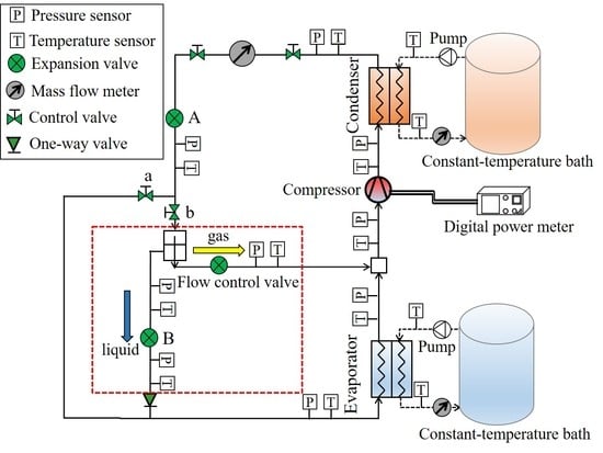
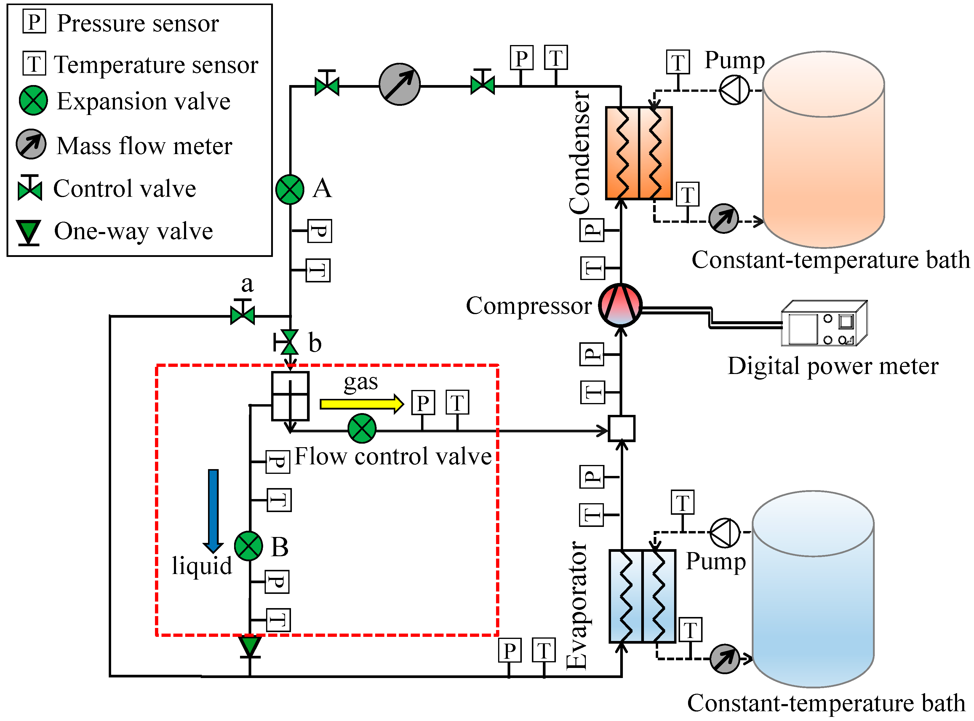
The above-mentioned single-stage refrigerant injection systems mostly concern the heating or cooling performance of a vapor or liquid injection system with a flash tank and accumulator together. Fewer studies have investigated the performance of a single-stage vapor injection heat pump with only a gas–liquid separator, especially when the system is operated under different primary temperatures and compressor frequencies. In this study, a single-stage heat pump with vapor injection has been developed by installing a small sized surface tension type gas–liquid separator instead of a flash tank to separate the vapor and liquid refrigerants. The vapor separated by the gas–liquid separator is injected to the inlet of the single-stage compressor. The performance of the developed vapor injection heat pump was investigated in order to understand the heating performance of the vapor injection heat pump under different compressor frequencies and primary temperatures.

2. Experimental Apparatus and Test Procedure

2.1. Experimental Setup

A conventional heat pump system includes four main components: compressor, condenser, expansion valve and evaporator. In this study, a single-stage heat pump with vapor injection is presented in Figure 1. The numbers in Figure 1a show the relevant junctions in the pressure-enthalpy (P-h) diagram of the heat pump cycle in Figure 1b. The heat pump system injects the refrigerant vapor separated by the gas–liquid separator into the inlet of the single-stage compressor (see Figure 1a), which is different from the traditional two-stage vapor injection heat pump, by injecting medium pressure refrigerant vapor into the injection port of a two-stage compressor.

2.1.1. Description of the Experimental Setup

The schematic of the experimental setup is illustrated in Figure 2, and the picture of this device is shown in Figure 3. It can be seen from Figure 2 that the experimental prototype can be divided into the heat pump evaluation fluid cycle and the refrigerant cycle. In terms of the heat pump evaluation fluid cycle, the user-defined flow rates and temperatures of the primary and secondary fluids can be provided by the heat pump evaluation system developed by our research group. There are two storage tanks in this heat pump evaluation system, one is filled with ethylene glycol solution (freezing temperature of −15 °C) to simulate the sink of the primary fluid, and the other one is filled with propylene glycol (boiling temperature of 187.4 °C) to simulate the heating load of the secondary fluid. The temperatures and flow rates of the primary and secondary fluids could be regulated by corresponding proportional–integral–derivative (PID) controllers.
On the refrigerant cycle side, the single-stage heat pump system with vapor injection and a basic conventional heat pump cycle can be realized by opening/shutting the two control valves installed after the expansion valve A. For the single-stage heat pump with a vapor injection cycle, the high temperature and high-pressure refrigerant gas is discharged by the compressor. Then, it flows into the condenser, releasing heat into the secondary fluid and turns into a high-pressure refrigerant liquid. The high-pressure refrigerant liquid flows through the mass flow meter, sight glass, and expansion valve A, and then enters the gas–liquid separator. The refrigerant liquid separated by the gas–liquid separator is turned into low pressure and low temperature two-phase refrigerant by the expansion valve B, then it enters the evaporator to absorb heat from the primary fluid to become low temperature and low temperature refrigerant vapor, and it merges the refrigerant vapor separated by the gas–liquid separator, before entering the single-stage compressor. When the control valve B installed in front of the gas–liquid separator is turned off and the control valve A turns on, the heat pump works as a conventional heat pump.
Table 1 describes the main characteristics of each component in the prototype of this experimental setup. An inverter-driven rotary compressor was used. A surface tension type gas–liquid separator was installed behind the expansion valve A. The pipes were sized to offer a low resistance to flow, and the pipe sizes were increased from 9.52 mm in the high pressure side to 15.88 mm in the low pressure side to avoid frictional losses. A rubber foam insulation material of 15 mm was incorporated to reduce the heat losses caused by the heat transfer between the refrigerant and surroundings. The refrigerant was R410A, and it was charged to the design conditions of 1.5 kg.

2.1.2. Instrumentation and Measurement

The specifications of temperature and pressure sensors to examine the state of refrigerant in the prototype are given in Table 2. The temperature and pressure sensors were installed at the geometrical center of connection tubes. The refrigerant pressure can be obtained from an absolute pressure transducer with a reported accuracy of ±1.0% of the full scale. The pressure losses of evaporator and evaporator can be calculated by the differences of indicated pressures installed at the inlet and outlet of the two heat exchangers. The refrigerant mass flow rate was measured by a Coriolis effect mass flow meter located at the outlet of the condenser, with a certified accuracy within ± 0.5% of the reading.
The performance of the heat pump at different compressor frequencies was measured at various primary fluid temperatures. The temperatures of primary and secondary fluids were measured by means of calibrated Pt100 thermal resistance (accuracy of ±0.15 °C), as shown in Table 3. The flow rates of the two kinds of brine as the primary and secondary fluids were measured by mass flow meters with a certified accuracy within ±0.25% of the span. The compressor electricity consumption was measured using a digital wattmeter, with a calibration specified uncertainty of ±0.1% of the reading. All of the sensor information was collected by a data acquisition system.
Both the brine side and refrigerant side heat transfer capacities can be obtained from the experimental results. The instant heating capacity Qc of the heat pump was calculated by the sensible heat obtained from the brine of the secondary side, as shown in Equation (1), and the instant heating COP was calculated by the following Equation (2):
Q c = G b , c ρ b , c c p , b , c ( T b , c 2 T b , c 3 )
COP = Q c W
Therefore, the average heating capacity Qc,avg and average heating COPavg in the testing time can be obtained according to the following equations:
Q c , avg = 0 τ Q c ( t )   d   t
COP avg = 0 τ Q c ( t )     d t 0 τ W ( t )     d t
For the refrigerant side, the heating capacity is calculated using Equation (5):
Q c , r = m ˙ c ( h 2 h 3 )
where m ˙ c is the refrigerant measured by the mass flow meter. The enthalpies of the joint point 2 and 3 can be decided by the measured temperature and pressure at the relevant point.
The instant cooling capacity Qe of the heat pump was calculated by the sensible heat obtained from the brine of the primary side as shown in equation (6), and the average heating capacity Qe,avg can be calculated in Equation (7):
Q e = G b , e ρ b , e c p , b , e ( T b , e 1 T b , e 4 )
Q e , avg = 0 τ Q e ( t )     d   t
The refrigerant side cooling capacity can be obtained using Equation (8):
Q e , r = m ˙ e ( h 1 h 4 )
where m ˙ e is the refrigerant mass flow rate in evaporator. For the heat pump cycle without vapor injection, m ˙ e = m ˙ c ; while, for the vapor injection heat pump cycle, m ˙ e = m ˙ c m ˙ inj , which is calculated according to the energy balance of the brine side cooling capacity Qe,avg. The enthalpies of the joint point 1′ and 4 can be decided by the measured temperature and pressure at the relevant point.
The energy balance between the brine side and the refrigerant side is evaluated in Figure 4, and the relatively small deviation of the heating capacities between the brine side and the refrigerant side is less than ±2.0%. The energy balance of the heat pump cycles can be checked in Figure 5 with a small deviation of ±2.0%.

2.2. Test Procedure

The experimental conditions are listed in Table 4, which was selected according to the northern Japanese climate (Köppen classification Dfb, and is very similar to central European or southeastern Canadian climates) for space heating [27]. During each experiment, the flow rate of the primary brine was fixed at 24 L/min, while the flow rate of the secondary brine was adjusted to make sure that the inlet and outlet temperature difference of the brine on the condenser side was 5 °C. The inlet temperature of primary fluid Tb,e1′ was examined at −5, 0, 5, 10 and 15 °C; whereas the temperature of the secondary fluid Tb,c3 flowing to the condenser was 30 °C; and the target temperature Tb,c2 for heat taken away by the secondary fluid was set at 35 °C to simulate the target space heating temperature. The examined compressor frequencies were 30, 50, 60, 75 and 90 Hz.
For each described experimental condition, the superheat controlled by the main expansion valve A at evaporator outlet was kept at 5 °C. The expansion valve B was kept fully open to ensure that as much refrigerant liquid as possible flowed into the evaporator. The steady state of the heat pump under each test condition must last at least 30 min, and the average heating capacity Qc,avg and average heating COPavg can be calculated by taking the average values of each parameter in Equations (3) and (4) under 30 min.
The refrigerant vapor separated by the gas–liquid separator m ˙ inj was injected into the suction line of the compressor through a mass control valve. According to the specification of the gas–liquid separator, the refrigerant injection ratio R could be calculated from the outlet refrigerant state of the expansion valve A and the total refrigerant mass flow rate, and it is typically defined using Equation (9):
R = m ˙ inj m ˙ c
For all the experimental conditions, the injection ratio R was not constant because the refrigerant vapor line was kept open by injecting all the separated vapor into the inlet of compressor.

3. Results and Discussion

3.1. Performance of Conventional Heat Pump without Vapor Injection

3.1.1. The Heating COPavg and the Heating Capacity Qc,avg Variations with the Compressor Frequency and Primary Temperature of the Conventional Heat Pump

The heating COPavg, heating capacity Qc,avg and power consumption Wavg of the conventional heat pump as a function of compressor frequency at different primary temperatures are shown in Figure 6, Figure 7 and Figure 8. It can be seen from Figure 7 that, as the compressor frequency increased, the heating capacity increased linearly, while the power consumption increased more with the frequency in Figure 8. Thus, the heating COPavg was decreased linearly with the compressor frequency for each tested primary temperature. When the inlet temperature of the primary fluid Tb,el′ was 15 °C, the heating COPavg at 90 Hz decreased by 33% compared to that at 30 Hz.
Since the inlet temperature of the primary fluid Tb,el′ corresponds to the evaporating pressure, when the evaporating pressure is higher, the heating COPavg is larger, as shown in Figure 6. The heating capacity increases with the evaporating pressure due to the incremental total mass flow rate of the refrigerant (see Figure 9) by sucking vapor with a low specific volume. Moreover, the lowered evaporating pressure induces the higher compression ratio which reduces the compression efficiency of compressor. Therefore, the heating COPavg is reduced when Tb,el′ is decreased.
In addition, the heating COPavg decreased more with the compressor frequency when the inlet temperature of the primary fluid Tb,el′ is higher because the power consumption increased more with the compressor frequency when at higher Tb,el′ as shown in Figure 8. The heating COPavg at 90 Hz decreased by 19% compared to that at 30 Hz when Tb,el′ is −5 °C, while the heating COPavg at 90 Hz decreased by 33%.

3.1.2. The Compressor Discharge Temperature and the Compression Ratio Variations with the Compressor Frequency and Primary Temperature in the Conventional Heat Pump

Figure 10 and Figure 11 show the compressor discharge temperature and compression ratio when the compressor is operated at different frequencies. The compressor discharge temperature and the compression ratio increased continually with the compressor frequency, with the same trend approximately. The increment of the compression ratio can be used to interpret the increase tendency of the power consumption of the compressor with the compressor frequency. The increasing compression ratio is the main reason for the decrease of heating capacity and increment of discharge temperature of compressor at low Tb,el′. When the heat pump is operated in an extremely cold region, the high discharge temperature would exceed the maximum discharge temperature of the single-stage compressor, and the heating capacity will decrease more significantly. Therefore, the adoption of vapor injection techniques is motivated to decrease the compressor discharge temperature and enhance the heating performance.

3.2. Performance of the Developed Vapor Injection Heat Pump

To see the effect of vapor injection on the heating performance of the single-stage heat pump with vapor injection, measurements were made at different compressor frequencies with a maximum injection ratio R at each test condition, as described in Section 2.2. It is supposed that the refrigerant vapor separated by the gas–liquid separator can be all injected into the suction port of the compressor because the flow control valve stays open during all the test conditions. Therefore, the injection ratio R can be calculated directly from the refrigerant state of outlet of expansion valve A.

3.2.1. The Effects of Vapor Injection on the Heating COPavg and the Heating Capacity Qc,avg

Figure 12 exhibits the effects of vapor injection on the heating COP of the heat pump in each test condition. It can be seen that the vapor injection heat pump cycle can increase the heating COP by 1.5–4% when the injection ratio R falls into the range 0.16–0.17. When the injection ratio R is lower than 0.13, the heating COP in the vapor injection heat pump cycle decreases, especially when the Tb,el′ is higher than 10 °C. The injection ratio R is larger when the Tb,el′ is low at the same frequency. This indicates that the cycle with vapor injection can be used to enhance the heating COP when the primary temperature Tb,el′ is low with a large injection ratio R. On the other hand, the injection ratio R decreases with the frequency at the test condition of the same Tb,el′, and the heating COP enhancement is likely to happen when the injection ratio is large with a low frequency at the same Tb,el′. It is beneficial for space heating application because the duration of heating loads corresponding to the low and medium compressor frequencies are long according to the heating load duration curve.
Figure 13 illustrates the variation of the normalized heating capacity Qc,avg-inj/Qc,avg with the injection ratio R of the vapor injection heat pump cycle. Referring also to Figure 9, it can be seen that, for both heat pump cycles without and with vapor injection, when the evaporating pressure is lower, the heating capacity Qc is smaller for the same frequency. The low evaporating pressure indicates that the specific volume of the refrigerant sucked by the compressor increases, hence the compressed mass of refrigerant decreases. As a result, the heating capacity Qc is reduced.
The tendency of the normalized heating capacity Qc,avg-inj/Qc,avg and the normalized heating COPavg-inj/COPavg as shown in Figure 12 was similar. The heat pump cycle with vapor injection in this study is likely to be slightly effective to increase the heating capacity Qc of the heat pump system when the injection ratio R falls into the range of 0.16–0.17.
Figure 14 shows the normalized power consumption Wavg-inj/Wavg with the injection ratio R of the vapor injection heat pump cycle, from which it can be seen that the power consumption of vapor injection heat pump cycle almost remains the same as that of the conventional heat pump cycle.

3.2.2. The Effects of Vapor Injection on the Discharge Temperature, the Compression Ratio of Compressor and Refrigerant Mass Flow Rate

The compression ratio CR decreases in the vapor injection cycle when the injection ratio R is higher than 0.16, especially when the evaporating pressure is low, as shown in Figure 15. The lower compression ratio CR indicates that the heat pump system can be operated with higher compressing efficiency and needs lower energy consumption.
As can be seen from Figure 16, the mass flow rate of the refrigerant m ˙ has been increased in the vapor injection heat pump cycle because of the smaller specific volume of suction refrigerant. In the vapor injection heat pump cycle, the vapor refrigerant flowing out of the evaporator is mixed with the separated vapor flowing after the gas flow control valve. Both the reduction of the refrigerant mass flow rate flowing through the evaporator and the injected vapor with a medium pressure in the vapor injection heat pump cycle have positive effects to obtain a higher suction pressure, and thus a smaller specific volume of the sucked refrigerant.
The increment mass flow rate in the vapor injection heat pump cycle is effective for obtaining a higher heating capacity Qc to a certain degree, except the injection ratio is lower than 0.13, as illustrated in Figure 13. Conversely, when the mass flow rate is too large, the heating capacity Qc will be reduced because of the limited condenser area. The condensing pressure will be decreased in this case, and the reduced heat transfer temperature difference between the refrigerant and the secondary fluid result in reduced heating capacity Qc.
Moreover, when the injection ratio R is higher than 0.16, the increased refrigerant mass flow rate of m ˙ and the decreased compression ratio CR can be used to see that the power consumption of the vapor injection heat pump cycle almost remains the same as that of the conventional heat pump cycle shown in Figure 14. In addition, the vapor injection heat pump cycle is beneficial to slightly reduce the compressor discharge temperature T2 when the injection ratio R is larger than 0.15, which can be seen in Figure 17.
Figure 18 shows the injection pressure Pinj with the change of injection ratio R in the vapor injection heat pump cycle. It shows that the lower the injection pressure Pinj, the higher the injection ratio R. In addition, the lower evaporating pressure is likely to receive a higher injection ratio R, which is slightly effective in enhancing the heating performance of the heat pump. When the heating performance cannot be enhanced, the experimental setup can be switched into the conventional heat pump cycle by turning on the control valve A and turning off the control valve B, seen in Figure 1. Moreover, the injection pressure Pinj increases with the increment of compressor frequency due to the installation of two expansion valves in the present experimental setup. Therefore, the methods (the necessity of the installation of expansion valve B in Figure 1) to decrease the Pinj will be discussed in further study.
An important feature of the developed vapor injection heat pump system is its simplicity. It does not need to be equipped with a two-stage compressor with a dedicated injection port as the classic vapor injection cycle does, which is usually more expensive than the single-stage compressor. Although an additional gas–liquid separator is required, the compacted vapor injection heat pump can provide a feasible and inexpensive way to improve the heating performance with a typical compressor. Moreover, it is thought that the developed vapor injection heat pump system can be applied to other heat pump system with refrigerants other than R410A, because the total mass flow rate of refrigerant flowing into the evaporator has been decreased, and thus the pressure loss between the inlet of evaporator and the suction port of the compressor can be reduced, as seen in Figure 19.

4. Conclusions

In this study, a vapor injection heat pump cycle by injecting vapor refrigerant separated by a gas–liquid separator into the suction port of a single-stage compressor has been developed. The performance of the developed single-stage vapor injection heat pump has been evaluated under different compressor frequencies and primary temperatures experimentally.
(1)
The vapor injection heat pump cycle can slightly increase the heat pump system’s heating capacity Qc and heating COP by 1.5–4% when the injection ratio R falls within the range 0.16–0.17.
(2)
The mass flow rate of the refrigerant m ˙ can be increased in the vapor injection heat pump cycle due to a decreased specific volume of the suction refrigerant.
(3)
The power consumption of the vapor injection heat pump cycle almost keeps the same with that of the conventional heat pump cycle due to the increased refrigerant mass flow rate and the decreased compression ratio CR.
(4)
It is found that the developed vapor injection cycle in this study is preferable to decrease the compressor’s discharge temperature.
(5)
The lower injection pressure Pinj is likely to get a higher injection ratio R, which is effective to enhance the heating performance of the heat pump.
When the heating performance cannot be enhanced, the experimental setup can be easily switched into the conventional heat pump cycle by turning on the control valve A. A very important feature of the developed single-stage vapor injection heat pump is its simplicity without an expansive two-stage compressor with a dedicated injection port as in the case of the classic vapor injection cycle. It is likely to be applied in the future to decrease the energy consumption and the CO2 emissions by improving the efficiency of heat pumps.

Author Contributions

H.L., K.N. drafted the work, conceived and designed the experiments; H.L. and Y.H. performed the experiments, and H.L. analyzed the data. H.L., K.N., T.K. and Y.H. gave the final approval of the version to be published. All authors have read and agreed to the published version of the manuscript.

Funding

This research was funded by New Energy and Industrial Technology Development Organization (NEDO) in Japan and National Natural Science Foundation of China, grant number 51906157.

Acknowledgments

The authors would like to thank SUNPOT Co. Ltd. for their help with the technical guidance for setting up the test bench.

Conflicts of Interest

The authors declare no conflicts of interest.

Abbreviation

COPCoefficient of performance
FTVIFlash tank vapor injection
IHXVIInternal heat exchanger vapor injection

Symbols

CPSpecific heat capacity (kJ/(kg∙K))
GVolumetric flow rate (m3/s)
hSpecific enthalpy (J/kg)
m ˙ Mass flow rate of refrigerant (kg/h)
PPressure (kPa)
QHeat transfer (kW)
RInjection ratio (-)
TTemperature (K)
WCompressor electric consumption (kW)
xQuality (-)
ΔPPressure drop (kPa)
ρDensity (kg/m3)
τTime (s)

Subscripts

avgAverage
bBrine
cCondenser
eEvaporator
injInjection
rRefrigerant
1,2,3,3′,4,5,6,6′,1′Junction number

References

  1. U.S. Energy Information Administration. International Energy Outlook 2019; U.S. Energy Information Administration: Washington, DC, USA, 2019.
  2. IEA Online Data Services. Available online: https://www.iea.org/reports/key-world-energy-statistics-2019 (accessed on 9 September 2019).
  3. Hundy, G.F.; Trott, A.R.; Welch, T.C. Chapter 25—Heat Pumps and Integrated Systems. In Refrigeration, Air Conditioning and Heat Pumps, 5th ed.; Hundy, G.F., Trott, A.R., Welch, T.C., Eds.; Butterworth-Heinemann: Oxford, UK, 2016; pp. 393–408. [Google Scholar]
  4. Neave, A. Heat pumps and their applications. In Plant Engineer’s Reference Book; Elsevier BV: Amsterdam, The Nederland, 2002; pp. 1–41. [Google Scholar]
  5. Blanco, D.L.; Nagano, K.; Morimoto, M. Impact of control schemes of a monovalent inverter-driven water-to-water heat pump with a desuperheater in continental and subtropical climates through simulation. Appl. Energy 2013, 109, 374–386. [Google Scholar] [CrossRef] [Green Version]
  6. Omer, A.M. Ground-source heat pumps systems and applications. Renew. Sustain. Energy Rev. 2008, 12, 344–371. [Google Scholar] [CrossRef]
  7. Zheng, N.; Wei, J. Performance analysis of a novel vapor injection cycle enhanced by cascade condenser for zeotropic mixtures. Appl. Therm. Eng. 2018, 139, 166–176. [Google Scholar] [CrossRef]
  8. Sun, J.; Zhu, D.; Yin, Y.; Li, X. Experimental investigation of the heating performance of refrigerant injection heat pump with a single-cylinder inverter-driven rotary compressor. J. Therm. Anal. Calorim. 2018, 133, 1579–1588. [Google Scholar] [CrossRef]
  9. Qi, H.; Liu, F.; Yu, J. Performance analysis of a novel hybrid vapor injection cycle with subcooler and flash tank for air-source heat pumps. Int. J. Refrig. 2017, 74, 540–549. [Google Scholar] [CrossRef]
  10. Lai, J.-C.; Luo, W.-J.; Wu, J.-Y. Performance analysis of single-stage air source heat pump utilizing indirect vapor injection design. Adv. Mech. Eng. 2018, 10, 1–12. [Google Scholar] [CrossRef] [Green Version]
  11. Xu, X.; Hwang, Y.; Radermacher, R. Performance comparison of R410A and R32 in vapor injection cycles. Int. J. Refrig. 2013, 36, 892–903. [Google Scholar] [CrossRef]
  12. Xu, X.; Hwang, Y.; Radermacher, R. Refrigerant injection for heat pumping/air conditioning systems: Literature review and challenges discussions. Int. J. Refrig. 2011, 34, 402–415. [Google Scholar] [CrossRef]
  13. Roh, C.W.; Kim, M.S. Comparison of the heating performance of an inverter-driven heat pump system using R410A vapor-injection into accumulator and compressor. Int. J. Refrig. 2012, 35, 434–444. [Google Scholar] [CrossRef]
  14. Cho, I.Y.; Seo, H.; Kim, N.; Kim, Y. Performance comparison between R410A and R32 multi-heat pumps with a sub-cooler vapor injection in the heating and cooling modes. Energy 2016, 112, 179–187. [Google Scholar] [CrossRef]
  15. Wang, X.; Hwang, Y.; Radermacher, R. Two-stage heat pump system with vapor-injected scroll compressor using R410A as a refrigerant. Int. J. Refrig. 2009, 32, 1442–1451. [Google Scholar] [CrossRef]
  16. Wang, X. Performance Investigation of Two-Stage Heat Pump System with Vapor-Injected Scroll Compressor. Doctorial Dissertation, University of Maryland, College Park, MD, USA, 2008. [Google Scholar]
  17. Wang, X.; Yu, J.; Xing, M. Performance analysis of a new ejector enhanced vapor injection heat pump cycle. Energy Convers. Manag. 2015, 100, 242–248. [Google Scholar] [CrossRef]
  18. Ma, G.-Y.; Chai, Q.-H. Characteristics of an improved heat-pump cycle for cold regions. Appl. Energy 2004, 77, 235–247. [Google Scholar] [CrossRef]
  19. Ma, G.-Y.; Zhao, H.-X. Experimental study of a heat pump system with flash-tank coupled with scroll compressor. Energy Build. 2008, 40, 697–701. [Google Scholar] [CrossRef]
  20. Heo, J.; Jeong, M.W.; Kim, Y. Effects of flash tank vapor injection on the heating performance of an inverter-driven heat pump for cold regions. Int. J. Refrig. 2010, 33, 848–855. [Google Scholar] [CrossRef]
  21. Yan, G.; Jia, Q.; Bai, T. Experimental investigation on vapor injection heat pump with a newly designed twin rotary variable speed compressor for cold regions. Int. J. Refrig. 2016, 62, 232–241. [Google Scholar] [CrossRef]
  22. Zhang, N.; Li, J.; Nan, J.; Wang, L. Thermal performance prediction and analysis on the economized vapor injection air-source heat pump in cold climate region of China. Sustain. Energy Technol. Assess. 2016, 18, 127–133. [Google Scholar] [CrossRef]
  23. Roh, C.W.; Kim, M.S. Effects of intermediate pressure on the heating performance of a heat pump system using R410A vapor-injection technique. Int. J. Refrig. 2011, 34, 1911–1921. [Google Scholar] [CrossRef]
  24. Heo, J.; Jeong, M.W.; Baek, C.; Kim, Y. Comparison of the heating performance of air-source heat pumps using various types of refrigerant injection. Int. J. Refrig. 2011, 34, 444–453. [Google Scholar] [CrossRef]
  25. Xu, S.; Niu, J.; Cui, Z.; Ma, G.; Shuxue, X.; Jianhui, N.; Zengyan, C.; Guoyuan, M. Experimental research on vapor-injected heat pump using injection subcooling. Appl. Therm. Eng. 2018, 136, 674–681. [Google Scholar] [CrossRef]
  26. Lee, D.; Seong, K.J.; Lee, J. Performance investigation of vapor and liquid injection on a refrigeration system operating at high compression ratio. Int. J. Refrig. 2015, 53, 115–125. [Google Scholar] [CrossRef]
  27. Blanco, D.L.; Nagano, K.; Morimoto, M. Experimental study on a monovalent inverter-driven water-to-water heat pump with a desuperheater for low energy houses. Appl. Therm. Eng. 2013, 50, 826–836. [Google Scholar] [CrossRef] [Green Version]
Figure 1. (a) The refrigerant cycle of the single-stage heat pump with vapor injection; (b) the pressure-enthalpy (P-h) diagram of a single-stage heat pump with vapor injection.
Energies 13 03133 g001aEnergies 13 03133 g001b
Figure 2. Schematic diagram of the experimental setup.
Energies 13 03133 g002
Figure 3. Picture of the experimental setup.
Energies 13 03133 g003
Figure 4. The energy balances of heating capacities.
Energies 13 03133 g004
Figure 5. The energy balances of the two heat pump cycles.
Energies 13 03133 g005
Figure 6. The heating coefficient of performance (COP)avg as a function of compressor frequency.
Energies 13 03133 g006
Figure 7. The heating capacity Qc,avg as a function of compressor frequency.
Energies 13 03133 g007
Figure 8. The power consumption Wavg as a function of compressor frequency.
Energies 13 03133 g008
Figure 9. The mass flow rate of refrigerant m ˙ as a function of compressor frequency.
Energies 13 03133 g009
Figure 10. The compressor discharge temperature T2 as a function of compressor frequency.
Energies 13 03133 g010
Figure 11. The compression ratio CRavg as a function of compressor frequency.
Energies 13 03133 g011
Figure 12. The variation of normalized heating COPavg-inj/COPavg with injection ratio R of the vapor injection heat pump cycle.
Energies 13 03133 g012
Figure 13. The variation of normalized heating capacity Qc,avg-inj/Qc,avg with the injection ratio R of the vapor injection heat pump cycle.
Energies 13 03133 g013
Figure 14. The normalized power consumption Wavg-inj/Wavg with the injection ratio R of the vapor injection heat pump cycle.
Energies 13 03133 g014
Figure 15. The normalized compression ratio CRavg-inj/CRavg with injection ratio R in the vapor injection heat pump cycle.
Energies 13 03133 g015
Figure 16. The normalized mass flow rate of the refrigerant m ˙ avg-inj/ m ˙ avg with the injection ratio R in the vapor injection heat pump cycle.
Energies 13 03133 g016
Figure 17. The effect of vapor injection on the compressor discharge temperature in the vapor injection heat pump cycle.
Energies 13 03133 g017
Figure 18. The injection pressure Pinj with the change of injection ratio R in the vapor injection heat pump cycle.
Energies 13 03133 g018
Figure 19. The normalized pressure drop ΔPinj/ΔP between the inlet of evaporator and the suction port of the compressor in the vapor injection heat pump cycle.
Energies 13 03133 g019
Table 1. Main components of the experimental setup.
ComponentTypeManufacturerSpecification
CompressorRotary type, inverter driveToshiba,Tokyo, JapanW < 2 kW, 900–7200 rpm,
T < 200 °C
Condenser/evaporatorBrazed plate heat exchangerAlfa Laval, Stockholm SwedenP < 4.5 MPa, 528 × 112 × 106 a, Ac, Ae = 1.9 m2
Expansion valveElectronic, bi-flowSaginomiya, Tokyo, Japan0 to 4.2 MPa, full opening: 5.5 mm, step controlled, 0–480
Gas–liquid separatorSurface tension typeNichirei Industries, Tochigi, JapanResin type
a Height × width × depth [mm].
Table 2. Measurement sensors installed in the experimental setup.
ComponentTypeProperties
Temperature sensorPt100In-tube installation, −30 < T < 200 °C, ±0.03%
Pressure sensorDigital pressure indicatorIn-tube installation, 0< P < 4 MPa (0 < P < 1 MPa for low pressure side), ±1.0% full scale
Mass flow meterCoriolis effectGr < 100 L/h, −40 °C < T < 127 °C, ±0.5%
Table 3. Uncertainties of experimental instruments.
ComponentTypeProperties
Temperature Pt100−30 °C < T < 200 °C, ±0.15 °C
Flow meterElectromagnetic flow meterGr < 50 L/min, T < 120 °C, ±0.25% of span
Power meterDigital power meter10 kW, ±0.1% of reading
Data loggerDigital measuring stationSample rate = 125 ms, ±0.05%
Table 4. Experimental conditions.
ParametersValues
Outlet temperature of secondary fluid Tb,c2 (°C)35
Inlet temperature of primary fluid Tb,e1′ (°C)−5051015
Compressor frequency (Hz)3050607590

