1. Introduction
Multiphase permanent magnet synchronous machines (m-φ PMSMs) have gained significant attention, in variable-speed drives and generation systems, during the last decade. They have attracted much interest becoming a viable solution for a wide range of modern industry applications such as aerospace applications, naval propulsion, energy generation and transportation electrification [
1,
2,
3].
The main reasons of this interest are justified by combining the well-known advantages of permanent magnet synchronous machines (PMSMs) in terms of high efficiency, high power density and high dynamic performances, with the strengths of multiphase machines, which provide lower torque ripple, lower current harmonics, fault tolerance capabilities and higher torque/power switch rating [
1,
4].
As mentioned in [
5], it is known that stator windings faults account for 40% of the overall electric machine failures in different industrial applications. As with any rotating electrical machine in healthy conditions, PMSMs undergo mechanical and electrical stresses symmetrically distributed inside the machine. In particular, the stator windings are subjected to several stresses induced by a combination of several factors, including thermal effects, vibrations, voltage spikes caused by adjustable-speed drives and environmental conditions [
5,
6].
Effectively, under healthy operating conditions, the phase impedances of the stator windings are identical, leading to balanced phase currents. When a stator fault occurs, phase currents are no longer balanced determining too high peak values, which may affect the performance and reliability of the motor.
Stator winding faults can be roughly classified as open-circuit or short-circuit, both affecting the phases and/or the terminal connections. Some other anomalies are not destructive at incipient stage but can evolve and initiate serious damages to the motors. During the last decade, high resistance connection (HRC) has been clearly identified as the main initiator of the stator failures. In fact, HRC is a progressive failure mode that can affect any power connection and/or end winding and is mostly caused by a combination of excessive vibration levels, poor workmanship, metal fatigue, overheating and/or corrosion of the power contact surfaces. Comprehensive descriptions of HRC mechanism propagation, initiated by the above factors, are available in [
6,
7,
8].
Although the advantageous performances of m-φ PMSMs over their classical 3-φ PMSMs counterparts, they are more subjected to stator faults owing to the higher number of stator windings. Thus, if such a fault is not properly cleared in a timely manner, it spreads and may conduct to rotor magnets demagnetization and eventual dramatic damages with serious unexpected outages [
9,
10].
Several techniques have been developed for the diagnosis of stator faults for three-phase machines. Classical off-line techniques such as measurement and comparison of winding resistances or related voltage drops, analysis of the temperature distribution by infrared thermography and partial discharge analysis, have been successfully applied [
11,
12,
13]. Even if standard off-line techniques provide reliable results for stator asymmetry, they are limited by the necessity of full or partial motor disassembly, and/or dedicated equipment or setup.
Actually, the four main diagnostic strategies, adopted to cope with the above limitations and to provide useful fault indexes and fault-tolerant control strategies, are known as model-based fault diagnosis, knowledge-based fault diagnosis, signal-based fault diagnosis and hybrid fault diagnosis approaches [
14,
15,
16]. Although the advantages of each approach, in general signal-based approach is the preferred strategy.
Stator fault diagnosis for 3-φ PMSMs has been extensively investigated in the literature [
5]. The main focus was on inter-turn short-circuit faults [
17,
18] and open-phase faults [
19], while investigations on HRC are relatively few, except recent studies presented in [
8,
20,
21]. Based on high order sliding mode principle, an interesting current-control scheme designed to simultaneously detect and tolerate the existence of HRC, was investigated in [
8]. The fault compensation is obtained by canceling extra current dynamics, which provides more effective
d–
q currents components tracking. In [
20], a full online diagnosis of HRC is developed for delta-connected PMSM using zero-sequence current component. The proposed approach has shown interesting performances for detecting and quantifying the extend of the fault. Another relevant approach dedicated to detecting and estimate the HRC severity, for vector-controlled PMSM drive system, is investigated in [
21]. The proposed technique is based on a signal injection in the reference signals applied to the controlled PMSM under its normal operation, leading to the appearance of DC components in the stator phase currents, used thereby for detecting and estimating the propagation degree of HRC.
With reference to m-φ PMSMs, much more efforts have been directed toward effective fault tolerant strategies than diagnosis approaches. Among several stator configurations of m-φ PMSMs, multiple three-phase winding sets are probably the most preferred for numerous industrial applications. The interest for these configurations of m-φ PMSMs is mainly justified by the fact that each stator winding set can be separately supplied by standard three-phase inverters, which allows crucial power flow modularity control, particularly useful under stator fault conditions.
Different control strategies for 6-φ PMSMs can be found in the literature, namely, constant V/f control, field-oriented control (FOC) and direct torque control (DTC). A recent comprehensive review, including theory, simulations, and experimental tests is presented in [
22]. Under the context of stator fault risks, several fault tolerant control techniques have been developed for exploiting the inherent active redundancy due to the associated precious degrees of freedom, for ensuring a continuity of operation even in case of more than one phase affected by a stator fault. An open-phase fault-tolerant control for 6-φ PMSM is developed in [
23], where the torque capability is maximized considering the overcurrent protection limits. In [
24], two optimal current control modes that tolerate open-phase fault, with minimum stator losses and maximum torque output, have been analyzed. A novel optimized open-phase fault tolerant control strategy is developed in [
25], where a genetic algorithm is used to maximize the average torque and minimize the torque ripple for post-fault operating condition. In [
26], an intelligent complementary sliding-mode control approach was developed for effective open-phase fault tolerance. To maintain the stability of the fault-tolerant control of the 6-φ PMSM drive system, a Takagi–Sugeno–Kang–type fuzzy neural network with asymmetric membership function was developed to estimate unknown lumped uncertainty including parameter variations, external disturbances and nonlinear friction force online.
Recently, effective diagnostic techniques dedicated to 6-φ PMSMs under stator fault conditions have been presented in [
26,
27,
28], for open-phase faults or inverter related-faults and in [
29] for short-circuits.
In [
27], both open-phase fault and open-switch fault are tolerated using a voltage compensation- based fault tolerant control. The detection process is based on real time monitoring of the current amplitude in a specific subspace, considering a predetermined threshold for alert. Diagnosis and fault tolerant approaches have been successfully developed in [
28] for open-phase faults, open-switch faults and short-switch faults in T-type three-level inverter fed dual-three phase PMSM drives. After fault detection process, which is based on the amplitude variations of a specific current space vector, an effective open-phase fault compensation was achieved without changing the machine model, nor the control framework. Open-switch faults and short-switch faults are tolerated by making full use of the remaining healthy-phases after faults. Although the verified good performances in terms of detection and fault-tolerance, the use of current amplitude space vector for the proposed diagnosis technique may show some limitations when changing the operating conditions of the machine. In [
29], a new magnetic equivalent circuit model for dual-three phase PMSM under winding short-circuit is proposed for accurate prediction of the fault impact.
Based on the above observations, the present contribution is aimed to present a new strategy of fault-detection and fault-tolerant control for 6-φ PMSMs affected by HRC. The existing papers on this type of fault are dealing with three-phase machines, but to the best of the author’s knowledge, no recent papers were published investigating HRC in 6-φ PMSMs. The presented strategy is based on the use of multiple space vector transformations for developing a new mathematical model able to deal with stator winding affected by HRC, and on the use of multi-reference frame current regulators for implementing an improved field-oriented control (IFOC) scheme.
The proposed strategy allows online fault-detection and fault-tolerance to be achieved without the need of additional hardware, in both stationary and dynamic operating conditions, as it is based on detecting the DC component of a new variable representing the Fault Index. In this way it is possible to avoid the critical problem of detecting certain current harmonic components having variable frequency depending on the operating speed.
This study is organized as follows. Modeling of the investigated 6-φ PMSM under HRC, in terms of multiple space vector, is presented in
Section 2. The proposed fault-detection and fault-tolerant control strategies are detailed in
Section 3. Numerical simulations and experimental tests are presented and commented in
Section 4 and
Section 5, respectively. The recommended Fault Index for quantifying the degree of HRC, as well as the corresponding simulation and experimental evaluations are presented in
Section 6.
3. Proposed Fault-Detection and Fault-Tolerant Strategy
In this section, the proposed strategy for an online fault-detection of HRC in 6-φ PMSM is presented. Then, an improved field-oriented control (IFOC) scheme based on appropriate stator currents control, which provides fault-tolerance against the investigated stator fault, is presented.
In order to better understand the principle of the proposed IFOC scheme and the associated online fault detection algorithm, it is useful to analyze the fault effects in the rotating reference frames, where the needed current regulators are conventionally implemented.
Taking into account a stator windings design with isolated neutral points as shown in
Figure 1, the current space vector in the
α3–
β3 subspace is equal to zero. Thus, the voltage equations expressed in the stator reference frame by Equations (4)–(6), can be limited to the 1st and 5th subspaces, corresponding to Equations (4) and (6), respectively. It is worth noting that for control purposes the voltage equations in
α1–
β1 subspace will be expressed in a reference frame (
d1–
q1) rotating at an angular speed of ω, whereas the equations in
α5–
β5 subspace will be expressed in a reference frame (
d5–
q5) rotating at an angular speed of 5 ω.
The transformation of the space vectors from stator reference frame to the rotating reference frame, regarding the 1st and 5th subspaces, can be carried out by using the following relationships
where
and
are the vectors in the new rotating reference frames, whereas
and
are the vectors expressed in the stationary reference frames.
Assuming isolated neutral points (
), substituting Equations (11) and (13) into Equations (4) and (6), respectively and taking into account Equations (21) and (22) leads to the following voltage equations written in rotating reference frames
where,
The space vectors and represent the voltage drops due to the stator HRC, in the d1–q1 and d5–q5 subspaces, respectively. In case of healthy conditions, and will be equal to zero as the only resistance component different from zero is , which is not present in Equations (25) and (26).
3.1. Proposed HRC Detection Approach
The effects of stator HRC can be identified by the presence of voltage space vectors
and
, expressed by Equations (25) and (26), respectively. The sensitivity of these voltages with respect to the HRC is established by their dependence on the new stator resistance components
,
and
. Assuming that, for the proposed IFOC scheme, the current space vector
is set to be equal to zero for reducing the torque ripple, the voltage space vectors, expressed by Equations (25) and (26), become
As can be seen, under the presence of unbalanced stator winding resistances, Equation (27) reveals the presence of a single fault harmonic component in the voltage space vector , which rotates at an angular speed of −2 ω with respect to d1–q1 plane.
In addition, for the considered stator fault, Equation (28) shows the presence of two additional harmonic components in the voltage space vector , which rotate at the two angular speeds of −4 ω and −6 ω with respect to d5–q5 plane.
At this point, it is very useful to recall that under healthy conditions, i.e., the six stator phase resistances are equal, the new stator resistance components , and become equal to zero, as well as the voltage space vectors and , leading to a clear identification of the healthy case.
Therefore, an effective fault-detection strategy, for 6-φ PMSM under HRC, can be based on tracking the contribution of the fault component at −2 ω in the voltage space vector , as well as the fault components −4 ω or −6 ω in the voltage space vector .
Taking into account the above conclusions, an effective control strategy that intends to tolerate such a stator HRC for 6-φ PMSM, should be based on monitoring the above tracked fault components, which is the subject of the next Subsection.
3.2. Proposed Fault Tolerant Control Strategy for HRC
Field-oriented control (FOC) strategy is a widely adopted control scheme for implementing closed-loop speed control for m-φ PMSMs. An improved field-oriented control (IFOC) scheme, based on appropriate stator currents control, which provides fault-tolerance against the investigated stator HRC, is presented in this subsection. The block scheme of the proposed control strategy is illustrated by
Figure 2.
The current regulators PI1.1 and PI5.1 are implemented in the synchronous reference frames d1–q1 and d5–q5, respectively, to ensure the tracking of currents references for torque control.
The reference currents iS5d,ref and iS5q,ref, in the d5–q5 plane, are set to zero for compensating possible torque oscillations due to the 5th and 7th harmonic of the field distribution generated by permanent magnets in the air–gap.
In order to compensate the negative effects of the seventh and eleventh harmonic of the back-emf, two further current regulators PI1.2 and PI5.2 are necessary. They are employed in two different reference frames synchronous with the corresponding back-emf harmonics. In particular, the space vectors of eleventh and seventh back-emf harmonics are both rotating at −12 ω, as shown by Equations (23) and (24), respectively.
The four current regulators PI1.1, PI5.1, PI1.2 and PI5.2 are used in both FOC and IFOC schemes. As highlighted in the voltage Equations (23)–(26), the presence of HRC introduces disturbing voltage vector drops and rotating at different angular speeds.
More specifically, with the adopted mathematical model, the latter quantities are exactly equal to Equations (27) and (28). Due to the disturbances introduced by these quantities, the current regulators PI1.1 and PI5.1 cannot track properly the reference values iS1d,ref, iS1q,ref, iS5d,ref and iS5q,ref.
To cope with these undesired effects, in IFOC scheme supplementary current regulators PI1.3 and PI5.3–PI5.4, have been implemented in reference frames synchronized with the different angular speeds of the voltage vectors drops and , respectively. Thus, a correct stator current reference tracking is ensured.
Finally, it is opportune to note that the generated output voltage of any supplementary regulator among PI1.3, PI5.3 or PI5.4, can be used for online detection of HRC affecting the stator phases of the 6-φ PMSM drive. In fact, in healthy conditions these voltages are practically zero, becoming different from zero only in case of a stator phase resistance asymmetry and showing an amplitude variation proportional to the severity of the fault.
4. Simulation Results
In order to verify the effectiveness of the proposed approach, the control scheme illustrated by
Figure 2 was implemented in Matlab/Simulink
™ for numerical simulations. The parameters of the machine are reported in
Table 1, which corresponds to the real machine used for the experimental validation. By combining the above control scheme with the 6-φ PMSM model, the implemented system allows a very detailed analysis of the whole drive under stator HRC, which is emulated by an additional resistance in series to Phase a1. The numerical simulations were realized at constant speed of 150 rpm, under the rated torque of 20 Nm. The reference signals
is1d,ref,
is5d,ref and
is5q,ref were set to zero. Three different operating conditions were analyzed.
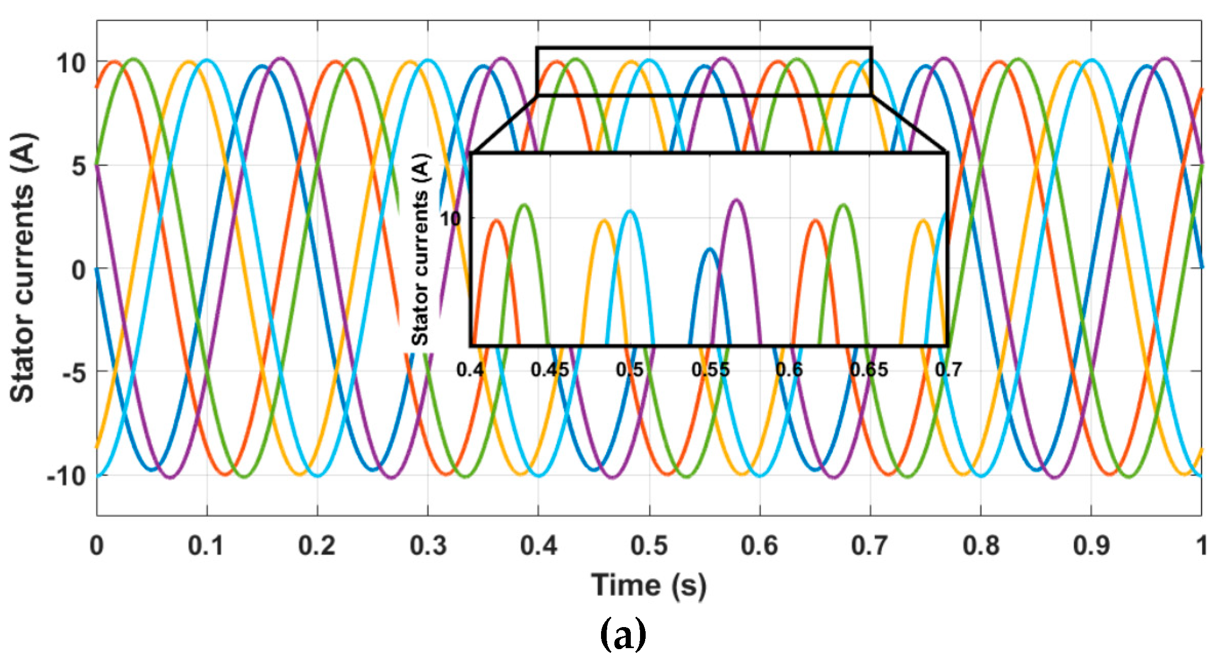
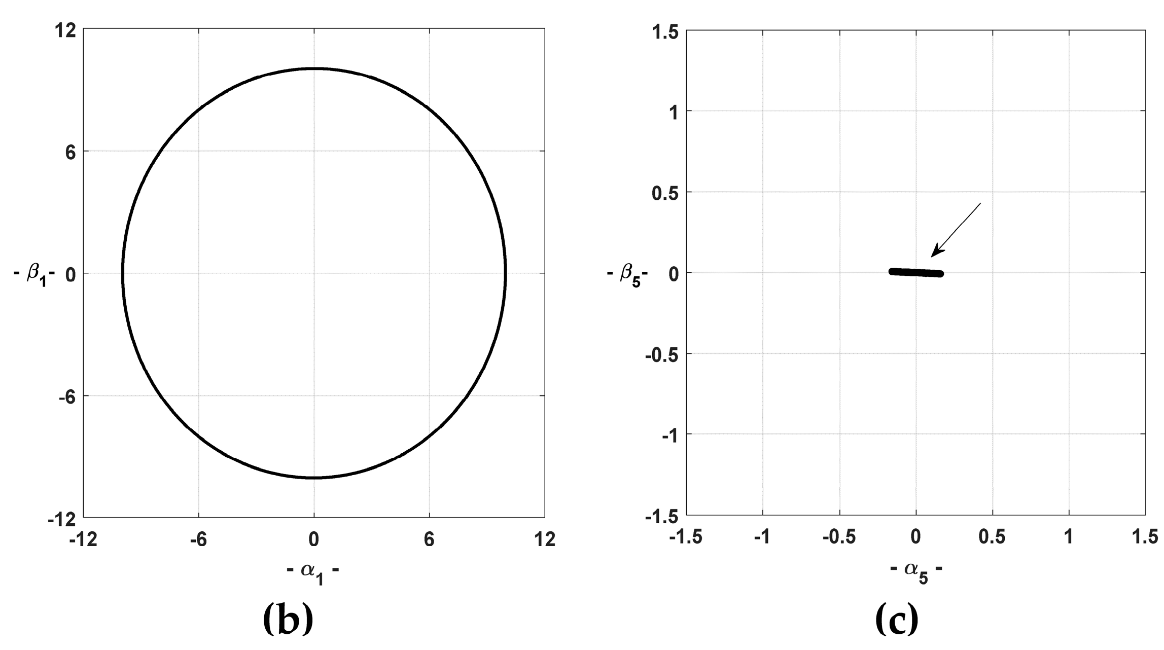
Initially, the healthy 6-φ PMSM is controlled by a conventional FOC scheme [
31], where the six phase resistances are equal. The corresponding simulation results, in terms of stator phase currents, are reported in
Figure 3a. The subsequent current space vectors, evaluated in the
α1–
β1 and
α5–
β5 planes, are reported in
Figure 3b,c, respectively. As can be seen in the zoomed area of
Figure 3a, the six-phase currents are balanced, leading to a circular behavior of the corresponding locus in plane
α1–
β1. The current space vector—evaluated in the
α5–
β5 plane—is equal to zero.
Under healthy condition where the six-phase resistances are identical, the resistance components
,
and
, expressed in Equations (8)–(10), respectively, are equal to zero. As a consequence, the voltage drops expressed by the space vectors
and
are equal to zero, leading to a healthy 6-φ PMSM. Thus, the circular trajectory observed in
Figure 3b is clearly justified by the dominance of the fundamental harmonic and the zero value in
Figure 3c is the absence proof of any resistance unbalance in the machine. From this starting point of the investigations, these results are considered as a reference for the next simulations under faulty conditions.
The second operating condition was realized with the same conventional FOC scheme, but with an additional resistance R
add = 250 mΩ (0.7 pu of healthy stator phase resistance Rs) in series with Phase a1, during 1.0 s of steady-state faulty conditions. The simulation results, in terms of stator phase currents and the corresponding current space vectors in planes
α1–
β1 and
α5–
β5, are reported in
Figure 4a–c, respectively. Under the considered stator fault, the six stator phase resistances are no more equal, leading to the existence of voltage drops expressed by the space vectors
and
. Thus, the stator symmetry of the machine is lost, which justify the current unbalance evidenced in the zoomed area of
Figure 4a, when compared to the healthy case (
Figure 3a).
It is worth noting that the behavior of the current space vector (
Figure 4b), evaluated in the
α1–
β1 plane, is mainly determined by the dominance of the fundamental current harmonic component with respect to the small contribution of an inverse component due to the unbalanced conditions. As a result, the trajectory is practically circular. The behavior variation in the current locus evaluated in plane
α5–
β5 (
Figure 4c) can be justified by the non-zero value of the space vector
under the actual stator asymmetry.
Finally, the proposed IFOC scheme illustrated by
Figure 2 was implemented under a faulty Phase a1 with an additional resistance (R
add = 0.7 pu) during 1.0 s of steady-state faulty conditions as in the previous simulation. The corresponding simulation results are reported in
Figure 5. As can be seen in the zoomed area of
Figure 5a, although the presence of the stator fault, the six phase currents show a balanced behavior.
In fact, this can be explained by the compensating effect assured by the current controller PI
1.3 against the disturbance introduced by the voltage space vector
in the synchronous reference frame
d1–
q1. The disturbances introduced by the voltage space vector
are cleared by the current controllers PI
5.3 and PI
5.4, in the synchronous reference frame
d5–
q5, leading to a zero value of the current space vector in the
α5–
β5 plane as can be seen in
Figure 5c.
At this level of investigation, the established theoretical analysis corroborates with numerical simulations results, confirming the effectiveness of the proposed fault-tolerant control.
5. Experimental Results
In order to experimentally validate the previous simulation results, a complete drive system was mounted in laboratory (see
Figure 6) and some experimental tests were carried out to verify the effectiveness of the proposed fault-detection and fault-tolerance strategies.
The experimental setup is composed of a six-phase MOSFET inverter and a six-phase surface mounted PMSM. The 6-φ PMSM parameters are reported in
Table 1. The controlled 6-φ PMSM is coupled to a three-phase induction machine used in generator mode to set the mechanical speed of the drive. During the experimental tests, the fault condition was emulated by an external resistor inserted in series with the machine Phase a1. The proposed IFOC scheme, presented in
Figure 2, was implemented on a TMS-320F2812 DSP based platform. The experimental tests were realized in steady-state condition at 150 rpm, and setpoint of the torque is 20 Nm, as in simulations of
Section 4. An oscilloscope with six channels was used for acquiring four phase currents and two control signals from the control platform, with a sampling rate of 100 kHz.
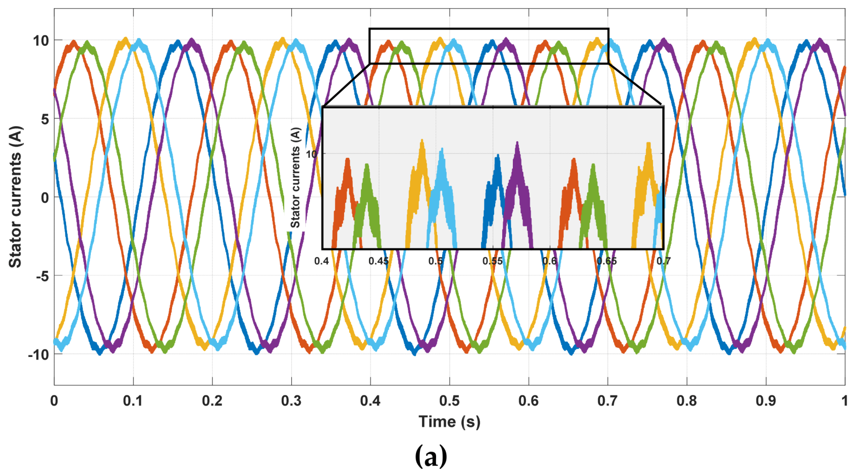
The behavior of the multiphase drive was assessed initially with healthy stator windings, then under a resistance increase of Phase a1 by 70%, during 1.0 s for each test. The obtained current waveforms under healthy, and faulty conditions are reported in
Figure 7a,b, respectively.
As can be seen, under healthy and faulty conditions, the six phase currents are balanced. Aside the small differences in amplitude that are probably due to measurement and acquisition chain accuracy, the six currents show practically the same waveforms.
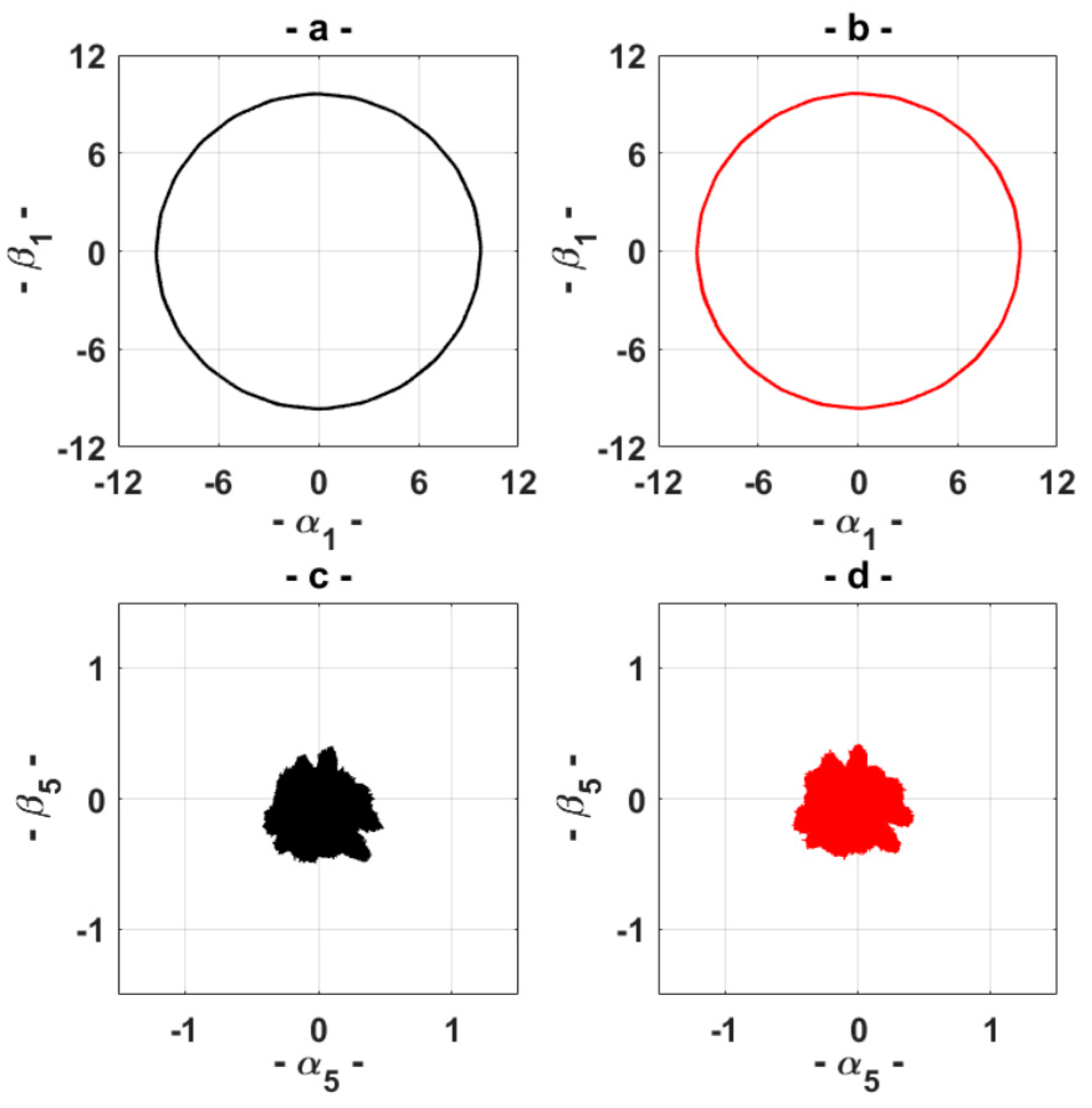
The corresponding current space vectors in planes
α1–
β1 and
α5–
β5, under healthy and HRC, are reported in
Figure 8. The current space vector in plane
α1–
β1, under healthy and HRC, shows a circular behavior (
Figure 8a,b), which confirms the theoretical analysis and the simulation results presented in
Figure 3b. The corresponding current loci in planes
α5–
β5, are reported in
Figure 8c,d, where a quasi-zero value can be observed (note the different axis scale). In fact, the latter behavior slightly different from zero is mainly caused by non-perfectly balanced conditions among the six stator phases due to manufacturing process, switching effects and measurement noise during data acquisition.
As can be seen, despite the presence of the fault, the proposed IFOC is able to ensure balanced stator phase currents. This can be clearly evidenced when comparing the obtained loci under healthy and HRC conditions (
Figure 8), which are practically identical.
Finally, considering the good performances of the proposed IFOC to maintain the system of six phase current balanced even under the presence of stator asymmetry, it is obvious that the use of the classical Motor Current Signature Analysis (MCSA) cannot be adopted for detecting the presence of HRC. Thus, a more appropriate fault index is necessary for online fault detection and quantification. This problem introduces the subject of the following Section.
6. Quantitative HRC Evaluation
Using the proposed IFOC, the 6-φ PMSM drive can maintain good operating conditions, even under degraded mode of the stator windings affected by HRC. In this context, the presence of an online fault-detection process which ensures not only the monitoring of the stator windings state, but also quantifying the severity of the stator winding resistance unbalance, is advisable.
As already anticipated in the previous theoretical analysis, a suitable online fault-detection strategy, for 6-φ PMSM under HRC, can be based on tracking the contribution of the fault component at −2 ω in the voltage space vector
, as well as the fault components at −4 ω or −6 ω in the voltage space vector
. Here, a new fault index “
Fi” is proposed, that is based on the
d–
q outputs of the controller
PI5.4 defined as
In order to test the sensitivity of the proposed fault index, different additional resistances (Radd) were tested in simulations, namely 0.10 Ω (0.28 pu), 0.25 Ω (0.70 pu), 0.75 Ω (2.09 pu) and 1.00 Ω (2.78 pu).
The spectra of the fault index, obtained from simulation results under healthy and faulty conditions, are reported in
Figure 9. Observing the obtained spectra, one can see the dominance of a DC component, which has the advantage to be easily detected even during speed variations.
It can be noticed that the tracked DC component shows a relevant increase in amplitude from healthy (Radd = 0.00 Ohms) to the first faulty case (Radd = 0.10 Ohms). It is also clearly evident that higher the severity of the fault (from 0.10 Ohms to 1.00 Ohms), higher the value of the fault index.
The corresponding spectra obtained from experimental tests for R
add (0.25 Ω, 0.75 Ω and 1.00 Ω) are reported in
Figure 10, respectively. As can be seen, the obtained experimental spectra corroborate with those obtained by simulations. It is worth noting that the experimental signals in
Figure 10 show a certain noise compared to
Figure 9 owing to an unavoidable small noise present in the measurement and acquisition chain.
In case of faulty conditions, the maximum difference from simulation to experimental results is lower than 2 dB. In healthy conditions, the differences appearing when comparing
Figure 9 and
Figure 10 are mainly due to measurement uncertainties, noting that the fault index is practically equal to zero in both simulation and experimental tests. More specifically, the fault index shows a relevant variation in amplitude (~15 dB) from healthy to the first faulty condition (R
add = 0.25 Ω). The proposed fault index has shown relevant increments in agreement with the fault severity also in experimental tests, leading to an effective fault index particularly adapted not only for fault-detection, but also for fault-quantification.
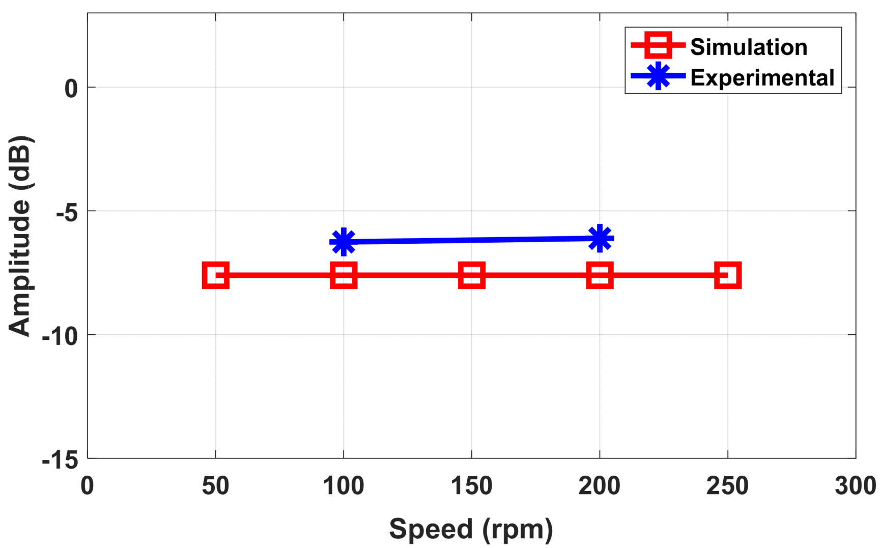
Finally, in order to show the performance of the proposed fault index against the operating speed, additional numerical simulations were carried out. The results achieved using a setpoint of the torque equal to 20 Nm as in previous tests and varying the speed from 50 rpm to 250 rpm, are shown in
Figure 11. As can be noted the fault index is not dependent on the speed, allowing a further advantage of the proposed fault index to be emphasized.
7. Conclusions
The main contribution of the study is the presentation of a new mathematical model of an asymmetric six-phase PMSM under HRC fault, which exploits the additional degrees of freedom given by the use of multi α–β planes adopted for describing the behavior of the machine. The presented mathematical model has a general validity, showing the possibility to investigate new diagnostic techniques based on monitoring the signals available in the multi α–β and d–q planes. In agreement with the developed mathematical model, an improved FOC scheme for asymmetric six-phase PMSMs based on the presence of several current regulators in the different α–β planes, was also presented. The proposed control scheme was adapted to provide not only an online HRC fault-detection and quantification, but also ensures a nearly undisturbed behavior of the drive.
The main features of the proposed HRC fault detection method are as follows:
No need of additional hardware or measurements as it makes use of the output voltage signals of a specific current regulator already available on the control board;
Reduced latency in detecting the fault, as it requires low computation time;
Fault index independent of the frequency, as it is based on DC-component monitoring;
Fault index independent of the speed of the operating conditions.
The results obtained, the theoretical analysis and the numerical simulations were compared with experimental results achieving a good agreement.
The presented results emphasize that the fault index was dependent on the severity of the fault, showing a good sensitivity. Adding a resistance of 0.25 Ω to a stator phase winding, a variation of about 15 dB was observed for the fault index magnitude.
Considering the above cited features of the proposed fault detection technique, the definition of the threshold should be adapted only to the torque demand.
Based on the results obtained the authors are encouraged to continue the experimental tests for verifying the effectiveness of the proposed diagnostic technique in dynamic conditions and to further develop the mathematical model for also achieving a reliable fault localization.

 ,
, 


