Article

A Novel Voltage Injection Based Offline Parameters Identification for Current Controller Auto Tuning in SPMSM Drives

1
Institute of Power Electronics and Electrical Drives, Harbin Institute of Technology, Harbin 150001, China
2
Department of Energy Technology, Aalborg University, 9220 Aalborg, Denmark
*
Author to whom correspondence should be addressed.
Energies 2020, 13(11), 3010; https://doi.org/10.3390/en13113010
Submission received: 6 May 2020 / Revised: 31 May 2020 / Accepted: 7 June 2020 / Published: 11 June 2020
(This article belongs to the Section E: Electric Vehicles)

Abstract

:
This paper presents a comprehensive study on a novel voltage injection based offline parameter identification method for surface mounted permanent magnet synchronous motors (SPMSMs). It gives solutions to obtain stator resistance, d- and q-axes inductances, and permanent magnet (PM) flux linkage that are totally independent of current and speed controllers, and it is able to track variations in q-axis inductance caused by magnetic saturation. With the proposed voltage amplitude selection strategies, a closed-loop-like current and speed control is achieved throughout the identification process. It provides a marked difference compared with the existing methods that are based on open-loop voltage injection and renders a more simplified and industry-friendly solution compared with methods that rely on controllers. Inverter nonlinearity effect compensation is not required because its voltage error is removed by enabling the motor to function at a designed routine. The proposed method is validated through two SPMSMs with different power rates. It shows that the required parameters can be accurately identified and the proportional-integral current controller auto-tuning is achieved only with very limited motor data such as rated current and number of pole pairs.

1. Introduction

Surface mounted permanent magnet synchronous motors (SPMSMs) are widely used in servo drives and electric vehicles due to their high efficiency, high torque density and good transient performance [1,2,3]. In many control schemes of SPMSMs, such as current controller auto-tuning, model predictive control and electromotive force (EMF) model based sensorless control, accurate values of stator resistance (Rs), d- and q-axes inductances (Ld and Lq) and permanent magnet (PM) flux linkage (ψf) are critical parameters that should be known to improve the control performance [4,5,6]. However, in many cases, the parameters are designed by the motor manufacturers and will not be accurately obtained prior to start up [7]. This has brought dilemmas in real applications and motivated the research on offline parameter identification.
Offline parameter identification has been widely studied in recent decades [7,8,9,10,11,12,13,14,15,16] due to its superior ability to provide motor parameters before the motor starts up [8,12]. Different signals are used in the control strategy to fulfill the parameter identification. Generally speaking, offline parameter identification can be divided into three categories: methods based on closed-loop controllers, methods that use open-loop signal injections and methods that combine both of them, respectively.
The already tuned current controller or speed controller is a must for parameter identifications that require closed-loop controllers [9,11,13,14,15]. A typical flow chart of this type of method is shown in Figure 1a [12]. With an already tuned current controller, Rs is calculated as the slope of voltage and current curves by injecting an increasing current into the d-axis [9,11]. Ld and Lq identifications are achieved by injecting high frequency (HF) sinusoidal current signals into d- and q-axes in [13,15], and the magnetic saturation effect caused by inductance variation is also considered. In [14,15], the ψf is identified with the already tuned speed controller and current controller, and issues that may cause identification inaccuracy, such as the influence from dead-time effects, are eliminated. However, it should be noted that the current and the speed controllers cannot be well-tuned without the information about the Rs, Ld, Lq, ψf, rotor moment of inertia and viscous frictional coefficient [4,12]. Some papers cited above tuned their needed controllers by trial and error, but this is based on experience and is rather time-consuming. By contrast, the identification methods based on open-loop signal injection are much easier [4,10,12]. By injecting voltage signals into the d- and q-axes in an open-loop manner, the required parameters are calculated according to the information of the injected voltages and current feedback. However, due to the absence of closed-loop controllers, problems, such as overcurrent protection, may potentially be triggered in the case of low-impedance motors [8]. In addition, the inductance cannot be identified at a specific saturation (current) point without the help of the current controller. Furthermore, there are still no techniques to properly control the motor speed without using a speed controller, which brings practical obstacles to ψf identification when using open-loop voltage injection methods.
The influence from inverter nonlinearity effects must be considered in parameter identification [14,16]. A direct way is to introduce proper compensation into the identification strategy [14,17,18]. However, this increases the complexity of the algorithm, and sometimes the inverter nonlinearities are too complex to be well compensated. By comparison, offline parameter identification methods that do not need such compensation have shown their unique superiority [12,13,16]. Notably, an open-loop based inductance identification without need of inverter nonlinearity compensation is proposed in [12]. However, similar methods to obtain Rs and ψf offline are still needed.
To sum up, voltage injection based offline parameter identification with controllable current or speed feedback and without requirement of inverter nonlinearity compensation is in great need in practical applications. Motivated by this, voltage signal injection based Rs, Ld, Lq and ψf identification for SPMSMs, which meets all the above-mentioned requirements, is proposed in this paper. The overall process can be achieved with very limited motor information such as the rated current (or maximum current) and number of pole pairs. A flow chart of the proposed method is shown in Figure 1b. More concretely:
(1) An increased voltage signal is injected through the d-axis, and the Rs is calculated using linear regression (LR) at standstill using the information from the voltages and currents.
(2) Two HF voltage signals (with different amplitudes but the same frequency) are injected through the d- and q-axes for Ld and Lq identification, and the Lq variation, which is caused by magnetic saturation, is also considered. In addition, with a predesigned voltage amplitude selection process, the desired HF voltage amplitudes are decided automatically, and current feedback is controlled properly.
(3) For ψf identification, a ramp voltage signal is given as the q axis voltage reference to excite the back EMF, and a proportional-integral (PI) type voltage controller is first proposed to control the motor speed. Influence from inverter nonlinearity is eliminated with the designed operation routine.
The rest of the paper is organized as follows: in Section 2, open-loop voltage injection based offline parameter identification with controllable current and speed is proposed. Section 3 gives the automatic tuning process of the PI current controller. In Section 4, the proposed method is verified on two SPMSMs with different rated powers, and Section 5 concludes the whole paper.

2. Offline Parameter Identification Methodologies

2.1. PMSM Mathematical Model

If neglecting iron core saturation, losses and considering stator current as a symmetrical three phase sinusoidal wave, the PMSM stator voltage Equations in a d-q frame can be described as in Equation (1):
[ u d u q ] = [ R s + p L d ω e L q ω e L d R s + p L q ] [ i d i q ] + ω e [ 0 ψ f ]
where ud and uq are d- and q-axes voltages, respectively. Rs is the stator resistance. Ld, Lq are the d- and q-axes inductances, respectively. ωe is the electrical angular velocity, id and iq are the current feedback of the d- and q-axes, respectively. ψf is the PM flux linkage, and p is the d/dt operator in time domain. For surface-mounted PMSM (SPMSM) and neglecting the inductance variation caused by magnetic saturation, Ld = Lq = L.

2.2. Stator Resistance Identification

2.2.1. Voltage Injection Based Stator Resistance Identification Methodology

The Rs identification method solely based on voltage injection is proposed in the following. Figure 2 shows the block diagram of the Rs identification. A linear increasing voltage signal, as expressed in Equation (2), is injected through the d-axis, and the real position feedback from the encoder is used for Park and inverse Park transmissions. By imposing voltage signals on u d * only ( u q * = 0 V), the induced current will keep the rotor self-fixed at its original position.
[ u d * ( k + 1 ) u q * ( k + 1 ) ] T = [ u d * ( k ) + Δ u d R s 0 ] T   ( if   i d ( k ) I max )
where u d * and u q * refer to the d- and q-axes voltage references, respectively, Δ u d R s is the incremental voltage to be added at each step, and Imax (RMS) is the maximum current of a given motor.
When the motor shaft is at standstill, the values of elements with ωe in Equation (1) are 0. Considering the voltage reference in Equation (2), Equation (1) is expressed by Equation (3). If the current increasing speed is relatively slow by controlling the injected voltage, the value of Ldpid in Equation (3) can be as small as several millivolts. Therefore, it can be ignored. Thus, the Rs can be calculated as the gradient of the ud and id curve during the voltage injection. Moreover, for the safety of a motor, a stop sign is added in Equation (4).
[ u d * u q * ] T = [ R s i d + L d p i d 0 ] T
[ u d * ( k + m ) u q * ( k + m ) ] T = [ 0 0 ] T   ( if   i d ( k ) = I max ,   m = 0 , 1 , 2 )
When considering the voltage errors from the inverter nonlinearity, the relationship between u d * and id is described as u d * = f ( i d ) = R ^ s i d + Δ u error during the voltage injection, where Δuerror refers to the lumped voltage errors caused by inverter nonlinearity effects and R ^ s is the identified stator resistance. By using the LR method for Rs identification, the relationship of R ^ s and Δuerror should satisfy j = 1 n ( Δ u error + R ^ s i d j u d j * ) 2 = min . Then, Equation (5) should stand:
{ ( Δ u error , R ^ s ) Δ u error = j = 1 n 2 ( Δ u error + R ^ s i d j u d j * ) = 0 ( Δ u error , R ^ s ) R ^ s = j = 1 n 2 ( Δ u error + R ^ s i d j u d j * ) i d j = 0
In addition, the solutions of R ^ s and Δuerror are [11]
{ R ^ s = ( j = 1 n i d j u d j * ) 1 n ( j = 1 n i d j ) ( j = 1 n u d j * ) ( j = 1 n i d j 2 ) 1 n ( j = 1 n i d j ) 2 Δ u error = 1 n ( j = 1 n u d j * ) ( j = 1 n i d j 2 ) 1 n ( j = 1 n i d j ) ( j = 1 n i d j u d j * ) ( j = 1 n i d j 2 ) 1 n ( j = 1 n i d j ) 2
where u d j * and idj are the d-axis voltage reference and current feedback at the j-th moment, and n is the amount of sampling number. This is described as Equation (7):
n = u d _ up R s u d _ low R s Δ u d R s + 1
where u d _ up R s and u d _ low R s are voltages that induce the up current limit and the low current limit in the selected current range when using Equation (6), respectively. The selection of these two current limits will be further addressed in Section 2.2.2.
Moreover, since the voltage reference is used in Equation (6), R ^ s should be the total values of stator resistance, resistance in the cables and IGBT on-state resistances. However, it is acceptable to use the identified Rs in algorithms such as current controller tuning and model predictive control, because they also use the voltage references in their models.

2.2.2. Valid Current Range Selection for Stator Resistance Identification

One prerequisite to use Equation (6) for Rs identification is that the Δuerror should be a constant; otherwise, the varied Δuerror may result in an ill convergence of the identified Rs. According to the relationship of Δuerror, id and u d * , as briefly shown in Figure 3 [19], the Δuerror only becomes a constant when the current is relatively high. This is also the reason why Rs identification is always suggested to be conducted at a high current level [9,20].
However, the moment that Δuerror becomes a constant is decided by configuration of the inverter (rated current of the IGBTs and switching frequency) in the test but not by a specific current or voltage value [19]. Thus, it is not reasonable to judge when to conduct Equation (6) only using current feedback. Comparatively speaking, it is wiser to suggest when to conduct Equation (6) using the variation of Δuerror. Therefore, a method that takes the change of Δuerror into consideration is proposed. It guarantees that the current range in Equation (6) has fully entered the saturated zone in Figure 3, and it is summarized in the following:
(1) The output voltage references are given according to Equation (2) from u d * (0) = 0 V.
(2) Equation (6) is conducted when id is within a relatively low current range, say (Ilow, Imedium). Δuerror and R ^ s , calculated using Equation (6), are defined as Δ u e r r o r ( 1 ) and R ^ s ( 1 ) .
(3) Equation (2) is continued and Equation (6) is repeated when id is between a specific current range, say (Imedium, Iup). Δuerror and R ^ s are calculated using Equation (6), and are renamed as Δ u e r r o r ( 2 ) and R ^ s ( 2 ) . The Ilow, Imedium and Iup are defined according to Equation (8), in which the α1, α2 and α3 should satisfy Equation (9).
I low = 2 · α 1 · I max ,   I medium = 2 · α 2 · I max ,   I up = 2 · α 3 · I max
α 1 < α 2 < α 3 < 1 ,   α 3 α 2 = α 2 α 1
(4) The values of Δ u e r r o r ( 1 ) and Δ u e r r o r ( 2 ) and the values of R ^ s ( 1 ) and R ^ s ( 2 ) are compared if:
Condition1: Δ u e r r o r ( 1 ) ≠ Δ u e r r o r ( 2 ) or R ^ s ( 1 ) R ^ s ( 2 ) ,
Condition2: Δ u e r r o r ( 1 ) ≈ Δ u e r r o r ( 2 ) and R ^ s ( 1 ) R ^ s ( 2 ) (say, the difference between Δ u e r r o r ( 1 ) and Δ u e r r o r ( 2 ) is less than 0.02 V and the difference between R ^ s ( 1 ) and R ^ s ( 2 ) is less than 0.02 Ω).
If the result meets Condition2, then the correct Rs is identified and R ^ s ( 1 ) is regarded as the result. The current range I > Ilow of Condition2 is designated as the valid current range for Rs identification under the specific inverter configuration used for test.
If the result meets Condition1, then α1, α2 and α3 are redefined in (10), but they should still satisfy Equation (9), and the processes in Equations (1)–(4) will be redone until the results meet Condition2 and finish an Rs identification. The repetitive current increase process from a low current is shown by the diagram at the bottom of Figure 3.
α n = α n + Δ α   ( Δ α < 1 ,   n = 1 , 2 , 3 )
For Condition1, Δ u e r r o r ( 1 ) ≠ Δ u e r r o r ( 2 ) or R ^ s ( 1 ) R ^ s ( 2 ) indicates that the current is still in the linear zone or straddles the linear zone and saturated zone, whereas for Condition2, Δ u e r r o r ( 1 ) ≈ Δ u e r r o r ( 2 ) and R ^ s ( 1 ) R ^ s ( 2 ) represent that the current is sufficiently high and has fully entered the saturated zone. The identified Rs is the desired value.
It should be noted, as stated above, the current value necessary for the Δuerror curve in Figure 3 to enter its saturated zone is decided by the configuration of the inverter. Therefore, the rated current of the power device can also be used as the baseline current to evaluate the valid current range for Rs identification. The reasons to use the Imax of a tested motor as the baseline in Equation (8) are as follows:
(1) The induced test current during the voltage injection should not exceed the Imax of a given motor; otherwise, safety issues such as overcurrent may occur in the motor.
(2) The rated current of the inverter is always higher than the Imax of the motor in a typical drive system, and if the induced current is smaller than Imax, then the safety of both the motor and the driver is guaranteed.
(3) The investigations in [9,20] show that the Imax of the tested motor is always beyond the current value corresponding to the knee point of Δuerror in Figure 3, so it is reasonable to use the Imax as a gauge to evaluate when Δuerror enters the saturated zone.

2.3. Voltage Injection Based d- and q-Axes Inductances Identification

The HF signal is one of the most commonly used methods for inductance identification. When an HF voltage in (11) is injected into the motor, the d-axis HF current response is in Equation (12):
[ u d * u q * ] T = [ U d _ inj sin ( ω h t ) 0 ] T
i d = I d h sin ( ω h t + φ )
where Ud_inj is the magnitude of the injected HF voltage, ωh = 2 × pi × fh (pi ≈ 3.1416 and fh is the injected frequency), φ is the phase angle between the resultant stator terminal voltage and current, and Idh is the amplitude of the induced HF current. From the Laplace transform and substituting s = h, the expression of Ud_inj is in Equation (13):
U d _ inj = R s 2 + L d 2 ω h 2 × I d h
As seen from Equation (13), if the fh is high enough, the ωh will be sufficiently high, then the voltage drop on inductive reactance is much higher than that on stator resistance. Thus, the solution of Ld is [9]:
L ^ d = U d _ inj / I d h ω h
where L ^ d is the identified d-axis inductance. In addition, it should be noted that the current distortion near the zero current clamping (ZCC) zone may affect the identification accuracy. In order to pull the induced current out of the ZCC zone, a small fixed dc voltage Ud_dc is added to u d * in Equation (11) to guarantee a more precise Ld identification.
As stated in [8], the values of stator inductances are affected by the magnetic saturation level (current magnitude). Since the SPMSM is mostly operated under i d * = 0 ( i d * is the d-axis current reference), the influence of the saturated effect on Ld can be neglected. However, the variations in Lq caused by the saturated effect should be considered. In this paper, the “dc+ac” voltage injection is used to extract Lq at a random saturation level, where the dc signal determines the saturation point and the ac signal is used to identify the Lq at that saturation point. When an HF voltage in Equation (15) is injected into the motor, the q-axis HF current response is in Equation (16):
[ u d * u q * ] T = [ 0 U q _ dc + U q _ inj sin ( ω h t ) ] T
i q = I q _ dc + I q h sin ( ω h t + φ )
where Uq_inj is the magnitude of the injected HF voltage, Iqh is the amplitude of the induced HF current, Uq_dc is the dc voltage signal, and its induced dc current is Iq_dc. The identified Lq is calculated in Equation (17) using a similar derivation of Equation (13) and Equation (14):
L ^ q = U q _ inj / I q h ω h
where L ^ q is the identified q-axis inductance.
However, when using the HF voltage signals for stator inductance identification, the following dilemmas are unavoidable:
(1) Due to the existence of inverter nonlinearity effects, the Ud_inj in Equation (14) and Uq_inj in Equation (16) are not the real voltages that impose on the motor. When considering the voltage errors caused by inverter nonlinearity effects, the real voltages that impose on the motor are rewritten using Equation (18):
U x _ inj _ r = U x _ inj Δ u error   ( x = d   or   q )
where Ud_inj_r and Uq_inj_r refer to the real voltages that impose on a motor and they should be used to replace Ud_inj and Uq_inj in Equation (14) and Equation (17), respectively.
(2) Due to the absence of a current controller, it is not easy to precisely determine the dc current Iq_dc in Equation (16). A strategy is proposed in [10] to approximate the Iq_dc using calculation of “Uq_dc/Rs”, but it should be noted that due to the influence of inverter nonlinearity effects, the induced Iq_dc is not a simple division of Uq_dc by Rs, and an incorrect Iq_dc will inevitably cause error to Lq identification.
(3) Due to the open-loop voltage injection based character, such as the method in [9,21], the amplitude of the excited HF current is not predictable. This may potentially trigger overcurrent protection, especially in case of low-impedance motors.
To solve the above-mentioned dilemma (1), two sets of HF voltage signals, with the same frequency (fh), same dc voltage component but different amplitudes Ud_inj1 and Ud_inj2 (or Uq_inj1 and Uq_inj2), are sequentially injected through the d-axis or q-axis voltage for Ld or Lq identification. According to Equation (14), if the detected current amplitude excited by Ud_inj1sin(ωht) is Idh1 and that excited by Ud_inj2sin(ωht) is Idh2, then the identified Ld can be calculated in Equation (19), and the Lq can be calculated in Equation (20) using a similar derivation. There are two advantages for using this method. (i) Both the dc voltage bias and current bias are removed by simple subtraction in denominators and numerators in Equation (19) and Equation (20). (ii) The voltage errors caused by inverter nonlinearity effects are eliminated; the detailed reasons for this will be further explained at the end of this Subsection.
U d _ inj 2 = L ^ d I d h 2 ω h ,   U d _ inj 1 = L ^ d I d h 1 ω h       L ^ d ω h ( I d h 2 I d h 1 ) = ( U d _ inj 2 U d _ inj 1 )     L ^ d = U d _ inj 2 U d _ inj 1 ( I d h 2 I d h 1 ) ω h
L ^ q = U q _ inj 2 U q _ inj 1 ( I q h 2 I q h 1 ) ω h
To solve the aforementioned dilemma (2) and dilemma (3), a general approach is proposed here which preserves the character of voltage injection and achieves a controllable current feedback during the stator inductance identification. First, a voltage signal, which is defined in Equation (21), is given as u q * to detect every Uq_dc that should exert on the motor for each desired saturation point (Iq_dc), while the u d * is kept as 0 V. The duration between every k to k+1 period in Equation (21) should be enough to make sure the induced Iq_dc has been fully stabilized at every dc voltage step. When the induced current achieves at a steady state, the excited Iq_dc(k) and its corresponding Uq_dc(k) are recorded accordingly. Second, in order to make sure the excited Idh and Iqh are in the controllable range, a voltage amplitude selection strategy to determine the values of Ux_inj1 and Ux_inj2 (x = d or q) is designed in the following:
After knowing the desired dc voltage at a specific saturation point (current level), two current thresholds are subjectively decided (defined as I l o w L and I u p L ). They are bigger than the dc current but close to each other. Then, a fixed frequency HF voltage signal is superposed upon the predetermined Ud_dc (for Ld identification) or Uq_dc (for Lq identification). The amplitude of the HF voltage signal is increased from 0 V. Voltage references during this process are shown by Equation (22), and the voltages that induce I l o w L and I u p L are set as Ux_inj1 and Ux_inj2 (x = d or q), respectively. The incremental voltage at each step can be relatively small for more accurate Ux_inj1 and Ux_inj2 (x = d or q) detection.
u q * ( k + 1 ) = u q * ( k ) + Δ u q L | k N +
u x * = U x _ dc + U x _ inj ( k ) sin ( ω h t ) | k N + U x _ inj ( k ) = U x _ inj ( k 1 ) + Δ u L U x _ inj ( 0 ) = 0 ,   ( x   =   d   or   q )
where Δ u q L in Equation (21) and ΔuL in Equation (22) are incremental voltage values to be added at each step.
Figure 4 is the block diagram of the proposed d- and q-axes inductances identification. Position information from the encoder is used to give the real position. For Ld identification, the signal injected in the d-axis enables the rotor to be self-fixed and the identification is achieved at standstill. For Lq identification, the q-axis current produces electromagnetic torque, which may rotate the rotor and affect the identification results, so the rotor shaft should be locked using a proper torque for Lq identification.
The reason that Equation (19) and Equation (20) can eliminate the voltage errors caused by inverter nonlinearity effects is as follows:
The numerators of Equation (19) and Equation (20) can be expressed by Equation (23). According to Equation (18), Equation (23) is rewritten as Equation (24).
U x _ inj 2 U x _ inj 1   ( x = d   or   q )
U x _ inj 2 _ r + Δ u error 2 U x _ inj 1 _ r Δ u error 1   ( x = d   or   q )
The inductance is identified under standstill, so the position feedback is a constant during the identification. As seen from Figure 3, when the current is high enough, the Δuerror is in the saturated zone, then Δuerror2 = Δuerror1 stands. When the current is in the linear zone, Δuerror2 ≠ Δuerror1, but with the proposed method to control the induced current, Equation (22) is able to decide Ux_inj2 and Ux_inj1 (x = d or q) and make their excitation current amplitudes Ixh2 and Ixh1 (x = d or q) quite close. Then, Δuerror2 ≈ Δuerror1 stands. That is to say that Δuerror is eliminated at both high current levels and low current levels by the two HF voltage injection method.

2.4. Voltage Injection Based PM Flux Linkage Identification

The q-axis voltage Equation is expressed in Equation (25). It can be seen that the ψf is associated with electrical angular velocity ωe, so the rotor movement is needed to excite the back-emf and compute the ψf accordingly. In this paper, the ψf identification is conducted under no load condition, and motor shaft free rotation is allowed.
u q * = R s i q + p L q i q + L d ω e i d + ω e ψ f
As seen from Equation (25), when the motor is at standstill, the existence of u q * will excite iq, and the iq will generate shaft torque, which enable the movement of the rotor. The induced back-emf will lessen the voltage drop on Rs, so the iq (shaft torque) is decreased. If the u q * is controlled properly, balanced voltage drops on Rsiq and ωeψf can be achieved, then the motor can be regulated at a speed steady state by controlling the u q * only. The reason for the existence of iq under no load is to generate proper torque to overcome the friction on the motor shaft. In addition, since the id of the SPMSM is always controlled to be 0 A and the Ld is very small (just several milli-henry), the value of Ldωeid in Equation (25) can be ignored compared with the value of ωeψf when the speed is not too low. An example can be given using parameters of motor #1 in Table 1. Supposing the speed is 300 r/min (which is 125.6 rad/s for ωe) and the variation on id is about 0.2 A, the maximum variation of Ldωeid is only 0.06, whereas the value of ωeψf is 13.95 V.
As stated in [14], the influence from inverter nonlinearities is a key factor influencing the identification accuracy of the ψf. Under the steady state condition and considering the influence from inverter nonlinearity effects, Equation (25) is rewritten as [16]:
u q * = R s i q + ω e ψ f - D q V d e a d
where DqVdead is the lumped voltage errors caused by inverter nonlinearity effects, Vdead is a constant that is related to the parameters of power devices, dc bus voltage and load condition, and Dq is a function of electrical angle θe and directions of the three phase currents [14]. The expression of Dq is in Equation (27), and the simulated waveform of Dq when using i d * = 0 control is shown in Figure 5.
D q = 2 cos ( θ e ) × sign ( i a ) + 2 cos ( θ e 2 / 3 × p i ) × sign ( i b ) - 2 cos ( θ e 1 / 3 × p i ) × sign ( i c )
where ia, ib and ic are A, B and C phase currents, pi ≈ 3.1416, and sign ( i ) = {     1 ,   i > 0 1 ,   i < 0 .
As seen from Figure 5, the voltage distortion caused by inverter nonlinearity effects on u q * is a combination of a dc component and a sixth-order distortion. It will deteriorate ψf identification accuracy, especially when the speed is relatively low. In order to get rid of the influence from DqVdead, different compensation methods are adopted in [14,22]. However, the methods also have some practical limitations. First, the polarity of phase currents cannot be accurately detected due to the zero current clamping effect. Second, the electrical angle detection error is inevitable, so the accuracy of Dq is affected, which consequently will affect ψf identification.
In this paper, 
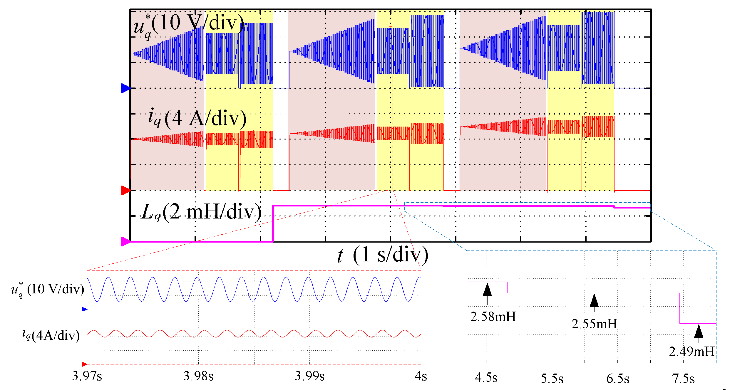
ψf identification which does not need inverter nonlinearity compensation and the establishment of a speed controller and current controller is proposed. The overall process is achieved by controlling the u q * , and its block diagram is shown in Figure 6. It is described as follows:
While the motor is at standstill under no load, the u q * is gradually increased, while the u d * is held as constant at 0 V. The torque excited by u q * will enable the speed to accelerate from 0 r/min. When the speed feedback arrives at ωm1, the speed is maintained to be ωm1 as much as possible by controlling u q * in Equation (28), and the speed steady state is kept at ωm1 for at least time period T1. The averages of the accumulated u q * , iq and ωe within T1 are calculated using Equation (29). Next, the u q * continues to increase in the ramp manner until the speed arrives at ωm2, similar to the process when the speed is at ωm1. The speed is maintained at ωm2 as much as possible by controlling u q * in Equation (28) for the duration of T2. Then, the mean values of the accumulated u q * , iq and ωe within T2 are calculated using Equation (30). Finally, the u q * is decreased gradually to 0 V and the ψf identification is finished. In addition, in order to guarantee that all the information is acquired under the speed steady state, the accumulation processes in T1 and T2 are started only when the speed has arrived at ωm1 and ωm2 after a little while.
u q * ( k ) = u q * ( k 1 ) + Δ u q ψ f ,   if   ω m ( k 1 ) < ω m n | n = 1   or   2   u q * ( k ) = u q * ( k 1 ) ,   if   ω m ( k 1 ) ω m n | n = 1   or   2
where Δ u q ψ f is the adjustment voltage on u q * to control the speed feedback and is designed to be relatively small so that the speeds in T1 and T2 will not suffer drastic variation and a speed steady state is achieved.
u ¯ q _ 1 * = 1 / N 1 k = 1 N 1 u q * ( k ) ,   i ¯ q _ 1 = 1 / N 1 k = 1 N 1 i q ( k ) ,   ω ¯ e _ 1 = 1 / N 1 k = 1 N 1 ω e ( k )
u ¯ q _ 2 * = 1 / N 2 k = 1 N 2 u q * ( k ) ,   i ¯ q _ 2 = 1 / N 2 k = 1 N 2 i q ( k ) ,   ω ¯ e _ 2 = 1 / N 2 k = 1 N 2 ω e ( k )
where u ¯ q _ 1 * ,   i ¯ q _ 1 and ω ¯ e _ 1 are the average values of the q-axis voltage, q-axis current and electrical angular velocity within T1, and u ¯ q _ 2 * ,   i ¯ q _ 2 and ω ¯ e _ 2 are those within T2. Besides, N1 = T1/Ts and N2 = T2/Ts, Ts is the sampling period. In this paper the Ts is equal to the pulse width modulation (PWM) switching period.
With Equation (29), Equation (30) and the already identified R ^ s , expressions of u ¯ q _ 1 * and u ¯ q _ 2 * can be expressed as follows:
u ¯ q _ 1 * = R ^ s i ¯ q _ 1 + ω ¯ e _ 1 ψ f 1 / N 1 k = 1 N 1 D q V d e a d ( k )
u ¯ q _ 2 * = R ^ s i ¯ q _ 2 + ω ¯ e _ 2 ψ f 1 / N 2 k = 1 N 2 D q V d e a d ( k )
In this way the sixth-order distortion on DqVdead becomes a constant. Subtracting Equation (31) from Equation (32), the ψf is calculated as:
ψ ^ f = ( u ¯ q _ 2 R ^ s i ¯ q _ 2 u ¯ q _ 1 + R ^ s i ¯ q _ 1 ) / Δ ω ¯ e
where ψ ^ f is the identified PM flux linkage, and Δ ω ¯ e = ω ¯ e _ 2 ω ¯ e _ 1 . The value of DqVdead is affected by load condition, since the ψf is identified under no load and the motor torque is mainly used to overcome the shaft friction. Thus, 1 / N 1 k = 1 N 1 D q V d e a d ( k ) and 1 / N 2 k = 1 N 2 D q V d e a d ( k ) in Equation (31) and Equation (32) can be regarded as having the same values [16,23], and they are eliminated by the subtraction in Equation (33). Hence, the voltage error caused by inverter nonlinearity is removed.

3. Current Controller Parameters Configuration

The tuning process of the PI current controller with the identified motor parameters has been well explained in [4], the schematic of the d- and q-axes current controller is shown in Figure 7, where i d * and i q * are the d- and q-axes current references. The decoupling voltages ud0 and uq0 are in Equation (34). According to [4], for q-axis, if the transfer function of the current controller is GACR = Kp_iq(1 + Kiq_iq/s), then the Ki_iq = Rs/Lq according to RsL pole cancellation, and the q-axis current closed-loop transfer function is in Equation (35).
u d 0 = L q ω e i q u q 0 = L d ω e i d + ω e ψ f
i q i q * = K p _ i q L q s + K p _ i q L q = ω i q s + ω i q
where s is the Laplace operator. ωiq is the cutoff frequency of q-axis current controller, and it can be set by the users. According to Equation (35), Kp_iq = Lqωiq. The gains for the d-axis current controller can be configured accordingly.

4. Experiment Results

The proposed parameter identification scheme is verified on two different SPMSMs: motor #1 is 110SJT-M040D with rated power as 1 kW, and motor #2 is 130SJT-M100D with rated power as 2.5 kW (GSK CNC EQUIPMENT CO., LTD, Guanzhou, China). Their available parameters on the datasheet are listed in Table 1. Both motors are controlled by a servo driver (GE2030T-LA1) (GSK CNC EQUIPMENT CO., LTD, Guanzhou, China) with digital signal processor (DSP) TMS320F28377s (Texas Instruments, Texas, USA) as the control chip. The current sampling frequency and the voltage reference update frequency are both 8 kHz, the speed sampling frequency is 4 kHz and the dead-time is 1.6 μs. A Magtrol dynamometer (Model: HD-815-8NA from Magtrol, Buffalo, USA) is used to provide torque to lock the motor shaft under Lq identification. The experiment platform is shown in Figure 8.
All experiment data are sampled using the DSP and transmitted to the upper monitor software in the computer: the transmission frequency is 8 kHz.

4.1. Voltage Injection Based Stator Resistance Identification

For Rs identification, motor #1 is used for valid current range selection first. Δ u d R s is designed small enough as 7.5 × 10⁻⁵ V, the initial values of α1, α2 and α3 in Equation (10) are set as 0.05, 0.1 and 0.15, respectively, and Δα is set as 0.05. It should be noted that the values of αn (n = 1, 2, 3) and Δα can also be set as other values, the settings detailed in this section are just to offer verification that the proposed method in Section 2.2.2. has the ability to find the valid current range for Rs identification. Related waveforms obtained by Rs identification using the LR method are shown in Figure 9; the shaft is aligned to θe = 0° during Rs identification. For better presentation, we divided the results into dots. The duration between two dots is 500 ms. The identified Rs of motor #2 is 0.37 Ω and the related waveforms are similar to those of motor #1 in Figure 9. Furthermore, it is noteworthy that the proposed method is able to determine the Rs but without the need to consider the current delay induced by inductance on the motor phase.
As seen from Figure 9, the results in Figure 9f meet Condition2: Δ u e r r o r ( 1 ) ≈ Δ u e r r o r ( 2 ) and R ^ s ( 1 ) R ^ s ( 2 ) in Section 2.2.2., whereas the results of Figure 9a–e belong to Condition1: Δ u e r r o r ( 1 ) ≠ Δ u e r r o r ( 2 ) or R ^ s ( 1 ) R ^ s ( 2 ) in Section 2.2.2, and it is apparent that the R ^ s in Figure 9a–e has bigger deviation compared with the R ^ s in Figure 9f. It approves the effectiveness of the method in Section 2.2.2, which selects a valid current range for LR to obtain an accurate Rs identification. Moreover, according to the results in Figure 9f, it should be noted that the selected valid current range (Ivalid > 5.73 A) for Rs identification is already beyond the 1 p.u. of the rated current of motor #1. This further shows that the concept “the Rs should be identified beyond 80% of the rated current” in [20] may not be suitable in all conditions, especially for motors with relatively low rated currents. Thus, the current range selection method for Rs identification proposed in this paper is more reasonable.

4.2. Voltage Injection Based d- and q-Axes Inductances Identification

As stated above, due to the fact that i d * = 0 for SPMSMs, Ld only needs to be identified under unsaturated condition, whereas the Lq variation caused by the magnetic saturation effect should be considered. The selection of the injected frequency fh is also a tricky task for HF based inductance identification. On the one hand, the fh should be as high as possible to increase the inductive impedance. On the other hand, a too high fh will result in very limited sampling points in a HF current period, which will influence the detection of Idh and Iqh. The fh is commonly set as or below one tenth of the sampling frequency (8 kHz in this paper). For tradeoff between identification accuracy and sampling rate, the fh is set as 500 Hz.
By injecting a stepped increase dc voltage in the q-axis in Equation (21), the relationship between iq and u q * of motor #1 at standstill is shown in Figure 10a; similar results for motor #2 at standstill are shown in Figure 11a. Values of u q * and iq in Figure 10a and Figure 11a can be regarded as Uq_dc and Iq_dc in Equation (15) and Equation (16) in Lq identification. In this way, the Lq can be identified at a random saturated point by voltage injection only. The identified Lq of motor #1 and motor #2 using the proposed method under different current levels are shown by red curves in Figure 10b and Figure 11b, respectively. Moreover, the identified Lq of motor #1 and motor #2 using methods in [9] are shown by blue curves in Figure 10b and Figure 11b, respectively. Good consistency of the results using two methods verifies the correctness of the proposed method. In order to avoid undesired shaft rotation, the motor shaft should be locked by the dynamometer with proper torque during the whole Lq identification in Figure 10 and Figure 11.
It should be noted that the inductance identification in [9] requires inverter nonlinearity compensation, and it is achieved using the look up table based compensation method in [24]. The voltage Δuerror that is used for inverter nonlinearity compensation is expressed in Equation (36), and the relationship of Δuerror and id at θe = 0° is shown in Figure 12.
Δ u error ( k ) = u d * ( k ) R ^ s i d ( k )
As seen from Figure 12, the Δuerror increases with the increase of id at the beginning and becomes a constant eventually. Moreover, the Δuerror has fully entered the saturated zone (with a value of 5.81 V approximately) when id = 5.73 A. This further verifies the valid current range selection for Rs identification in Figure 9.
The Lq identification process of motor #1 at x A (x = 8, 9 and 10) is shown in Figure 13.
In Figure 13, the dc voltages at these current levels are obtained from the results in Figure 10a and are set as 13.51 V, 14.61 V and 15.73 V, respectively. Voltage thresholds Uq_inj1 and Uq_inj2 in Equation (20) are chosen as ac voltage amplitudes that induce [x × (1 + 0.05)] A and [x × (1 + 0.1)] A (x = 8, 9, 10), respectively. Figure 13 shows the injected voltage amplitude selection process (waveforms in pink background), the 2 HF voltage injection process (waveforms in yellow background), and the identified Lq under different saturation levels. A decrease Lq can be seen with the increase of dc current, and this is caused by magnetic saturation effect.
The Ld only needs to be identified under unsaturated condition for SPMSMs, and the waveforms for motor #1 and motor #2 are quite similar, so only the Ld identification results of motor #1 are shown in Figure 14. In order to pull the excited id out of the zero current clamping zone, a small dc offset (2 A) that will not cause a severe magnetic saturation effect is added to the HF voltage signal.
The waveforms in pink, grey and green background in Figure 14 represent the injected voltage amplitude selection, two HF voltage injection and Ld calculation processes. The identified Ld for motor #2 using similar methods under 2 A dc offset is 1.07 mH.

4.3. Voltage Injection Based PM Flux Linkage Identification

The waveforms of ψf identification in motor #1 are shown in Figure 15, in which the ωm1 is set as 300 r/min and ωm2 is set as 500 r/min.
As seen from Figure 15a,c, the speed steady state can be easily achieved by controlling the u q * . It is noteworthy that big current oscillation happens on iq, and the oscillation frequency changes with the speed variation. This might be caused by the current measurement offset error according to analysis in [25]. The average calculation in Equation (31) and Equation (32) can be used to extract the average values of iq under the conditions of ωm1 and ωm2. Moreover, it should be noted that in Figure 15b a short time is needed for iq to reach the steady state after the speed arrives at ωm1 or ωm2. Therefore, the calculations in Equation (31) and Equation (32) should also be started after the speed has reached the preset reference for a while. The identified ψf of motor #2 using the same method is 0.127 Wb, and the waveforms are similar to those in Figure 15.
To sum up, the identified Rs, Ld, Lq and ψf of motor #1 and motor #2 are shown in Table 2. For both motors, the deviations between the identification results and the offline measured values are less than 7%. The accuracy of the methods in this paper is adequate to be potentially applied for the purposes of current controller tuning (PI parameter configuration) (the work in [4] allows a deviation less than 11%), current predictive control (where a 10% parameter deviation is allowed in model predictive control without robust algorithms [26]) or sensorless control (the work in [10] allows a deviation less than 7%).

4.4. Current Controller Auto-Tuning

With the identified parameters, the PI current controller of motor #1 is configured according to the contents of Section 3. The expected cutoff frequencies of the current loop of the d- and q-axes are both set as 1 kHz (namely, ωid = ωiq = 2 × pi × 1000). The sinusoidal (1kHz) and step reference tracking tests are given through the d-axis and the results are shown in Figure 16. The d- and q-axes current waveforms during the speed step (0–1000 r/min) process are given in Figure 17.
It can be seen from Figure 16a,b that good current tracking ability can be obtained when the current controller is automatically tuned. In Figure 16a, the amplitude attenuation ratio between the feedback current and reference current is about 0.71, and the phase delay between the sinusoidal reference and feedback currents is about 32°. In Figure 17, the q-axis current tracking performance is deteriorated at the q-axis current saturation zone when decoupling voltages are not added, and this can be well enhanced when the decoupling voltages are added.

5. Conclusions

In this paper, a novel voltage injection based offline parameter identification is proposed to obtain Rs, Ld, Lq and ψf in a given SPMSM and achieve an auto-tuned current controller, and the main contributions are:
(1) The overall identification strategies are totally independent from the current controller and speed controller. Moreover, they can be completed automatically with very limited data that are accessible from the nameplate of an SPMSM, such as rated current and number of pole pairs. Thus, they can be easily adopted in industrial applications.
(2) Simple voltage amplitudes selection processes are designed in this paper. Together with the open-loop voltage injection strategies, the proposed methods are able to detect the inductance variation at a random saturation (current) level for a given motor. Meanwhile, it achieves a controllable current and speed by automatically deciding the voltage reference during the entire identification process. These are not achievable in the conventional voltage injection based methods due to the open-loop character.
(3) Practical issues that may influence the identification accuracy, such as valid current range selection for Rs identification in a specific inverter configuration and identification errors that are caused by inverter nonlinearity effects, are carefully addressed in this paper. This further improves the accuracy of parameter identification.
The proposed method is experimentally validated through two SPMSMs with different power rates. The results show that the identification errors are less than 7%, which is sufficient for high dynamic current controller auto-tuning for SPMSM drive systems.

Author Contributions

Conceptualization, J.L. and M.Y.; methodology, J.L.; software, J.L. and Y.C.; validation, J.L., Y.C. and M.Y.; formal analysis, J.L. and M.Y.; data curation, J.L. and Y.C.; writing—original draft preparation, J.L.; writing—review and editing, J.L., Y.C. and M.Y.; supervision, M.Y., D.X. and F.B.; funding acquisition, M.Y. and D.X. All authors have read and agreed to the published version of the manuscript.

Funding

This research was funded by National Natural Science Foundation of China, Project 51690182 and grants from the Power Electronics Science and the Education Development Program of the Delta Environmental & Educational Foundation, DREK2017004.

Acknowledgments

The authors of this paper would like to thank the support from GSK CNC EQUIPMENT CO., LTD, Guangzhou, China for this research.

Conflicts of Interest

The authors declare no conflicts of interest.

References

  1. El-Sousy, F.F.M. Intelligent optimal recurrent wavelet elman neural network control system for permanent-magnet synchronous motor servo drive. IEEE Trans. Ind. Inform. 2013, 9, 1986–2003. [Google Scholar] [CrossRef]
  2. Zhang, C.; Wu, G.; Rong, F.; Feng, J.; Jia, L.; He, J.; Huang, S.; Fei, R. Robust fault-tolerant predictive current control for permanent magnet synchronous motors considering demagnetization fault. IEEE Trans. Ind. Electron. 2018, 65, 5324–5334. [Google Scholar] [CrossRef]
  3. Hu, J.; Peng, T.; Jia, M.; Yang, Y.; Guan, Y. Study on electromechanical coupling characteristics of an integrated electric drive system for electric vehicle. IEEE Access 2019, 7, 166493–166508. [Google Scholar] [CrossRef]
  4. Yang, S.-M.; Lin, K.-W. Automatic control loop tuning for permanent-magnet AC servo motor drives. IEEE Trans. Ind. Electron. 2016, 63, 1499–1506. [Google Scholar] [CrossRef]
  5. Yang, M.; Lang, X.; Long, J.; Xu, D. Flux immunity robust predictive current control with incremental model and extended state observer for PMSM drive. IEEE Trans. Power Electron. 2017, 32, 9267–9279. [Google Scholar] [CrossRef]
  6. Wu, T.; Luo, D.; Huang, S.; Wu, X.; Liu, K.; Lu, K.; Peng, X. A fast estimation of initial rotor position for low-speed free-running IPMSM. IEEE Trans. Power Electron. 2020, 35, 7664–7673. [Google Scholar] [CrossRef]
  7. Kwon, Y.-S.; Lee, J.-H.; Moon, S.-H.; Kwon, B.-K.; Choi, C.-H.; Seok, J.-K. Standstill parameter identification of vector-controlled induction motors using the frequency characteristics of rotor bars. IEEE Trans. Ind. Appl. 2009, 45, 1610–1618. [Google Scholar] [CrossRef]
  8. Odhano, S.A.; Pescetto, P.; Awan, H.A.A.; Hinkkanen, M.; Pellegrino, G.; Bojoi, I.R. Parameter identification and self-commissioning in AC motor drives: A technology status review. IEEE Trans. Power Electron. 2019, 34, 3603–3614. [Google Scholar] [CrossRef] [Green Version]
  9. Wang, G.; Qu, L.; Zhan, H.; Xu, J.; Ding, L.; Zhang, G.; Xu, D. Self-commissioning of permanent magnet synchronous machine drives at standstill considering inverter nonlinearities. IEEE Trans. Power Electron. 2014, 29, 6615–6627. [Google Scholar] [CrossRef]
  10. Peretti, L.; Zigliotto, M. Automatic procedure for induction motor parameter estimation at standstill. IET Electr. Power Appl. 2012, 6, 214–224. [Google Scholar] [CrossRef]
  11. Wang, Q.; Zhang, G.; Wang, G.; Li, C.; Xu, D. Offline parameter self-learning method for general-purpose pmsm drives with estimation error compensation. IEEE Trans. Power Electron. 2019, 34, 11103–11115. [Google Scholar] [CrossRef]
  12. Erturk, F.; Akin, B. Spatial inductance estimation for current loop auto-tuning in IPMSM self-commissioning. IEEE Trans. Ind. Electron. 2020, 67, 3911–3920. [Google Scholar] [CrossRef]
  13. Odhano, S.A.; Bojoi, R.; Rosu, S.G.; Tenconi, A.; Bojoi, I.R. Identification of the magnetic model of permanent magnet synchronous machines using DC-biased low-frequency AC signal injection. IEEE Trans. Ind. Appl. 2015, 51, 3208–3215. [Google Scholar] [CrossRef]
  14. Liu, K.; Zhu, Z.Q.; Zhang, Q.; Zhang, J. Influence of nonideal voltage measurement on parameter estimation in permanent-magnet synchronous machines. IEEE Trans. Ind. Electron. 2011, 59, 2438–2447. [Google Scholar] [CrossRef]
  15. Odhano, S.A.; Giangrande, P.; Bojoi, I.R.; Gerada, C. Self-commissioning of interior permanent-magnet synchronous motor drives with high-frequency current injection. IEEE Trans. Ind. Appl. 2014, 50, 3295–3303. [Google Scholar] [CrossRef]
  16. Liu, K.; Feng, J.; Guo, S.; Xiao, L.; Zhu, Z.Q. Identification of flux linkage map of permanent magnet synchronous machines under uncertain circuit resistance and inverter nonlinearity. IEEE Trans. Ind. Inform. 2018, 14, 556–568. [Google Scholar] [CrossRef]
  17. Gong, L.M.; Zhu, Z.Q. A novel method for compensating inverter nonlinearity effects in carrier signal injection-based sensorless control from positive-sequence carrier current distortion. IEEE Trans. Ind. Appl. 2011, 47, 1283–1292. [Google Scholar] [CrossRef]
  18. Seyyedzadeh, S.M.; Shoulaei, A. Accurate modeling of the nonlinear characteristic of a voltage source inverter for better performance in near zero currents. IEEE Trans. Ind. Electron. 2019, 66, 71–78. [Google Scholar] [CrossRef]
  19. Bedetti, N.; Calligaro, S.; Petrella, R. Self-commissioning of inverter dead-time compensation by multiple linear regression based on a physical model. IEEE Trans. Ind. Appl. 2015, 51, 3954–3964. [Google Scholar] [CrossRef]
  20. Wang, K.; Yao, W.; Chen, B.; Shen, G.; Lee, K.; Lu, Z. Magnetizing curve identification for induction motors at standstill without assumption of analytical curve functions. IEEE Trans. Ind. Electron. 2015, 62, 2144–2155. [Google Scholar] [CrossRef]
  21. Feng, G.; Lai, C.; Iyer, K.L.V.; Kar, N.C. Improved high-frequency voltage injection based permanent magnet temperature estimation for PMSM condition monitoring for EV applications. IEEE Trans. Veh. Technol. 2018, 67, 216–225. [Google Scholar] [CrossRef]
  22. Liu, K.; Zhu, Z.Q. Online estimation of the rotor flux linkage and voltage-source inverter nonlinearity in permanent magnet synchronous machine drives. IEEE Trans. Power Electron. 2014, 29, 418–427. [Google Scholar] [CrossRef] [Green Version]
  23. Kim, H.W.; Youn, M.-J.; Cho, K.Y.; Kim, H.-S. Nonlinearity estimation and compensation of PWM VSI for PMSM under resistance and flux linkage uncertainty. IEEE Trans. Control Syst. Technol. 2006, 14, 589–601. [Google Scholar] [CrossRef]
  24. Pellegrino, G.; Bojoi, I.R.; Guglielmi, P.; Cupertino, F. Accurate inverter error compensation and related self-commissioning scheme in sensorless induction motor drives. IEEE Trans. Ind. Appl. 2010, 46, 1970–1978. [Google Scholar] [CrossRef] [Green Version]
  25. Chung, D.-W.; Sul, S.-K. Analysis and compensation of current measurement error in vector-controlled AC motor drives. IEEE Trans. Ind. Appl. 1998, 34, 340–345. [Google Scholar] [CrossRef]
  26. Morel, F.; Lin-Shi, X.; Retif, J.-M.; Allard, B.; Buttay, C. A Comparative study of predictive current control schemes for a permanent-magnet synchronous machine drive. IEEE Trans. Ind. Electron. 2009, 56, 2715–2728. [Google Scholar] [CrossRef] [Green Version]
Figure 1. Flow chart comparison of offline parameter identification for surface mounted permanent magnet synchronous motors (SPMSMs): (a) flow chart of a traditional offline parameter identification [12]; (b) flow chart of the proposed offline parameter identification.
Energies 13 03010 g001
Figure 2. Block diagram of Rs identification.
Energies 13 03010 g002
Figure 3. The relationship between the d-axis voltage reference and current feedback in self-commissioning conditions (u in vertical coordinate can refer to u d * or Δuerror).
Energies 13 03010 g003
Figure 4. Block diagram of d- and q-axes inductances identification.
Energies 13 03010 g004
Figure 5. Waveform of the Dq.
Energies 13 03010 g005
Figure 6. Block diagram of ψf identification.
Energies 13 03010 g006
Figure 7. Schematic of d- and q-axes current controller.
Energies 13 03010 g007
Figure 8. Experiment platform.
Energies 13 03010 g008
Figure 9. Experiment Rs identification results (Motor #1, 2 I m a x = 19 . 1 A ): (a) Ilow = 0.96 A, Imedium = 1.91 A, Iup = 2.87 A; (b) Ilow = 1.91 A, Imedium = 2.87 A, Iup = 3.82 A; (c) Ilow = 2.87 A, Imedium = 3.82 A, Iup = 4.78 A; (d) Ilow = 3.82 A, Imedium = 4.78 A, Iup = 5.73 A; (e) Ilow = 4.78 A, Imedium = 5.73 A, Iup = 6.69 A; (f) Ilow = 5.73 A, Imedium = 6.69 A, Iup = 7.64 A.
Energies 13 03010 g009
Figure 10. Lq identification results of motor #1: (a) relationship of u q * and iq; (b) Lq identification results under different saturated conditions.
Energies 13 03010 g010
Figure 11. Lq identification results of motor #2: (a) relationship of u q * and iq; (b) Lq identification results under different saturated conditions.
Energies 13 03010 g011
Figure 12. Waveforms of id and Δuerror of motor #1 under θe = 0°.
Energies 13 03010 g012
Figure 13. Lq identification results of motor #1 at 8 A, 9 A and 10 A.
Energies 13 03010 g013
Figure 14. Ld identification results of motor #1 at 2 A.
Energies 13 03010 g014
Figure 15. ψf identification results of motor #1: (a) waveform of q-axis voltage reference; (b) waveform of q-axis current; (c) waveform of electrical angular velocity; (d) identified permanent magnet (PM) flux linkage.
Energies 13 03010 g015
Figure 16. Performance of auto-tuned current controller in motor #1: (a) 1 kHz sinusoidal waveform tracking test; (b) step reference test.
Energies 13 03010 g016
Figure 17. Speed step test of motor #1: (a) without the decoupling voltages (ud0 and uq0); (b) with decoupling voltages (ud0 and uq0).
Energies 13 03010 g017
Table 1. Main parameters of SPMSMs.
ParameterSymbolMotor #1Motor #2
Rated powerP01.0 kW2.5 kW
Rated torqueT04 N·m10 N·m
Rated speedn02500 r/min2500 r/min
Rated current (RMS 1)I04.5 A10.0 A
Maximum current (RMS)Imax13.5 A30.0 A
dc bus voltageUdc300 V300 V
Number of pole pairsp044
Stator resistance 2Rs1.05 Ω0.35 Ω
d- and q-axes inductances 2 (unsaturated)L2.58 mH1.04 mH
Rotor PM flux linkage 2ψf0.111 Wb0.122 Wb
1 RMS is short for Root Mean Square. 2 For reference, the parameters are measured offline in advance.
Table 2. Identification results summary.
Motor #1Motor #2
ParameterRs (Ω)Ld1 (mH)Lq1 (mH)ψf (Wb)Rs (Ω)Ld1 (mH)Lq1 (mH)ψf (Wb)
Reference1.052.582.580.1110.351.041.040.122
Identified1.082.682.670.1160.371.071.110.127
Deviation2.9%3.9%3.5%4.5%5.7%2.9%6.7%4.1%
1 The identified stator inductances are compared under unsaturated condition, and Lq identification results under saturated condition are compared in Figure 10 and Figure 11.

