Boiling Heat Transfer Performance of Parallel Porous Microchannels

 ,
,
Abstract
:
1. Introduction
2. Experimental Setup and Procedure
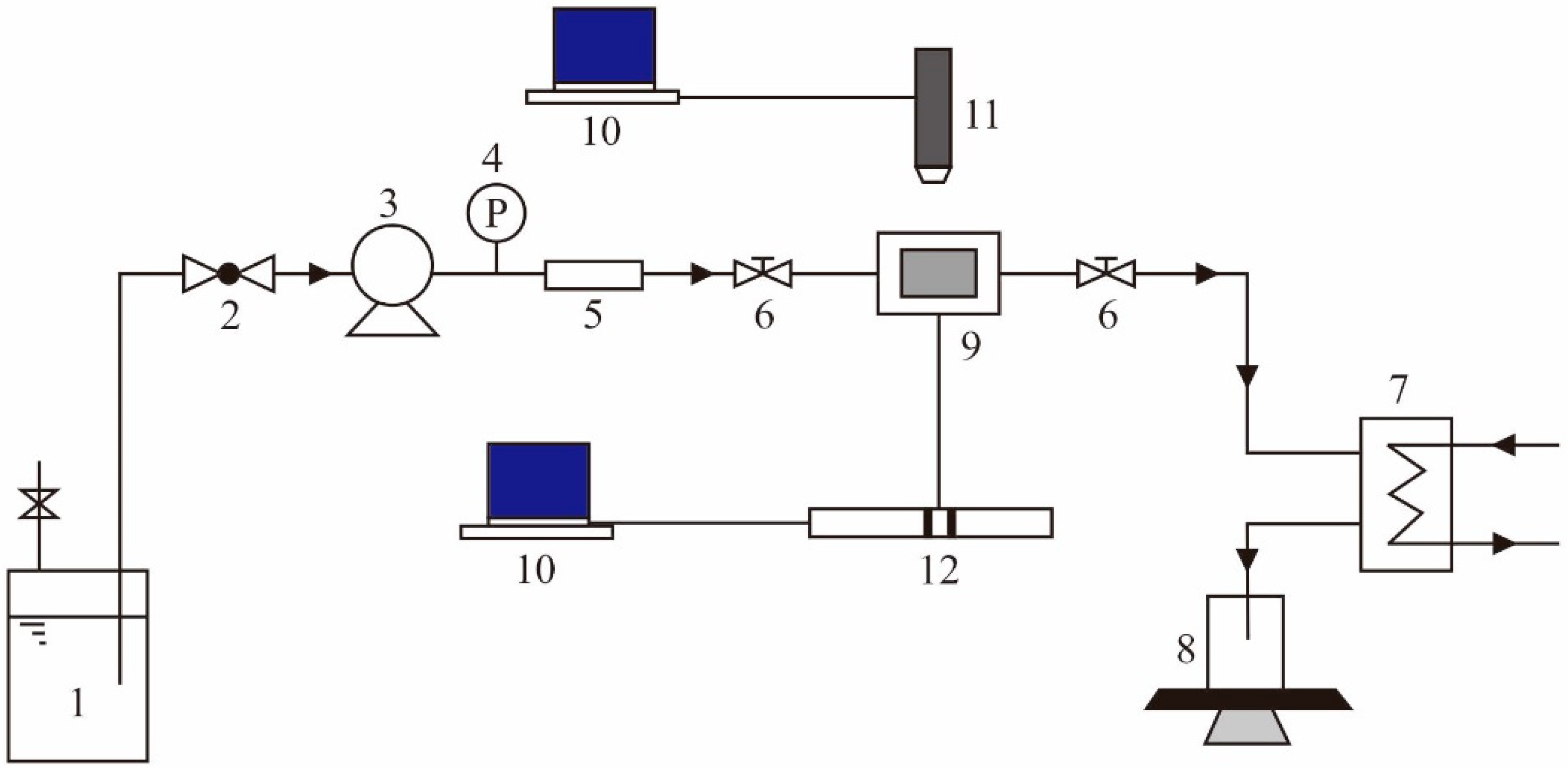
2.1. Testing System
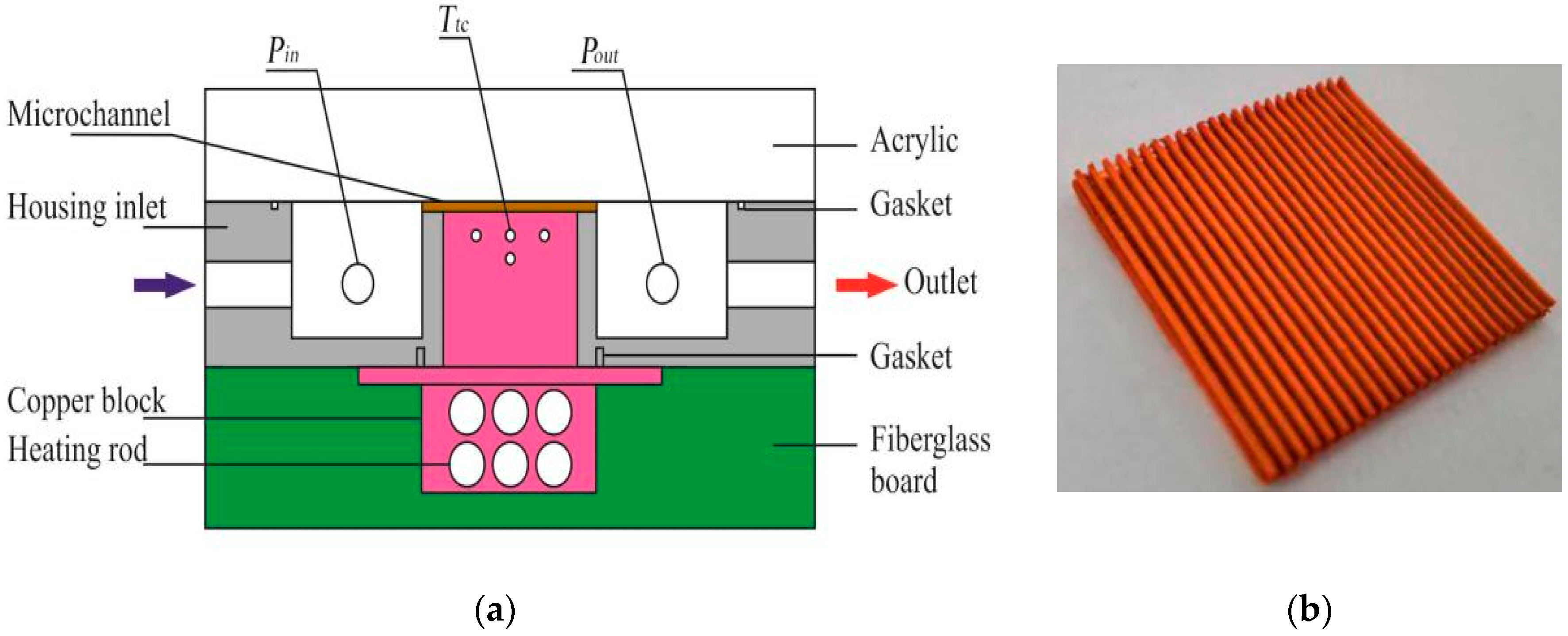
2.2. Test Section
2.3. Experimental Procedures
2.4. Data Reduction
3. Fabrication Processes of Porous Microchannel
4. Experimental Results
4.1. Flow Boiling Heat Transfer Coefficient of Microchannels
4.2. The Influence of Porous Structural Parameters
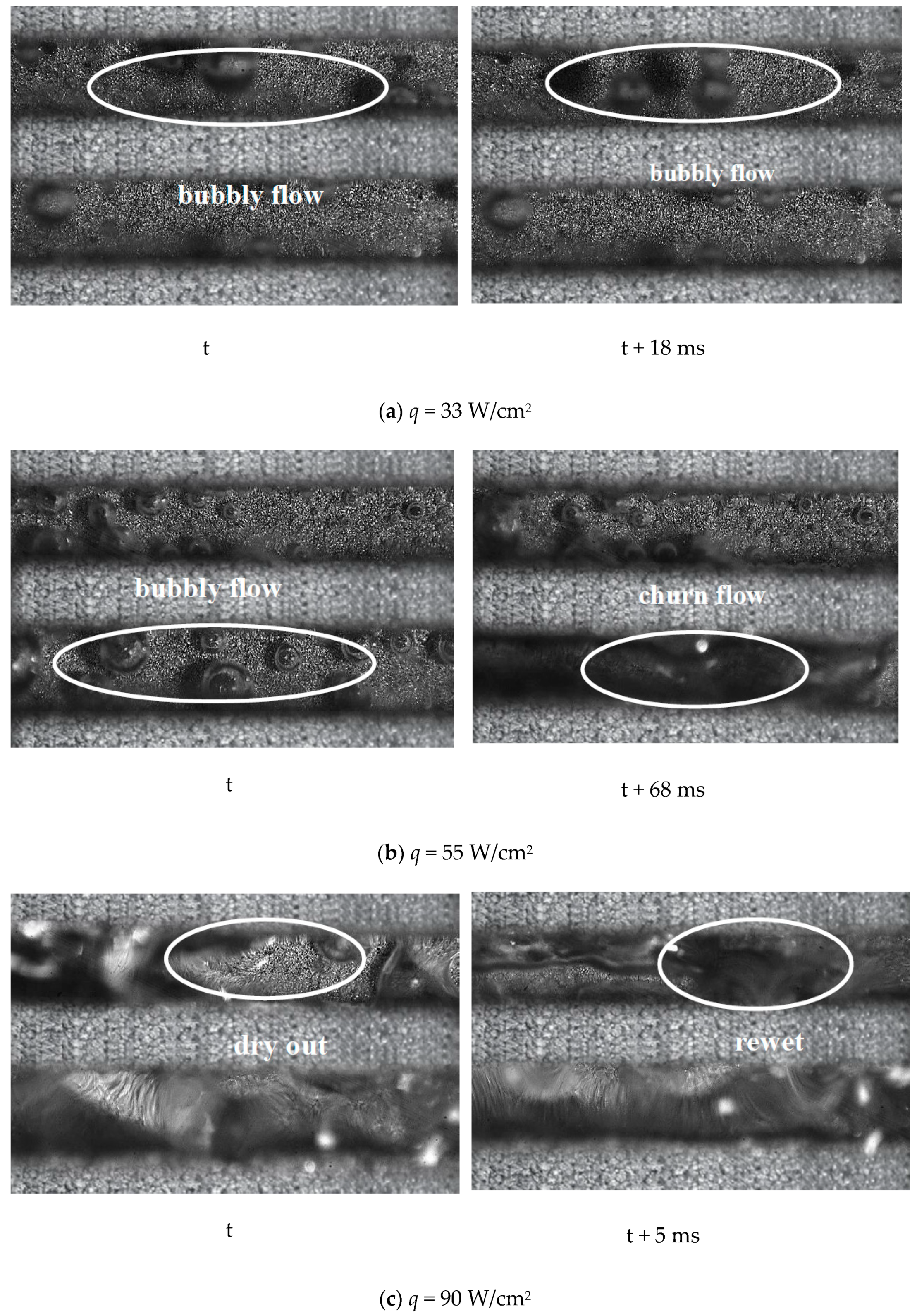
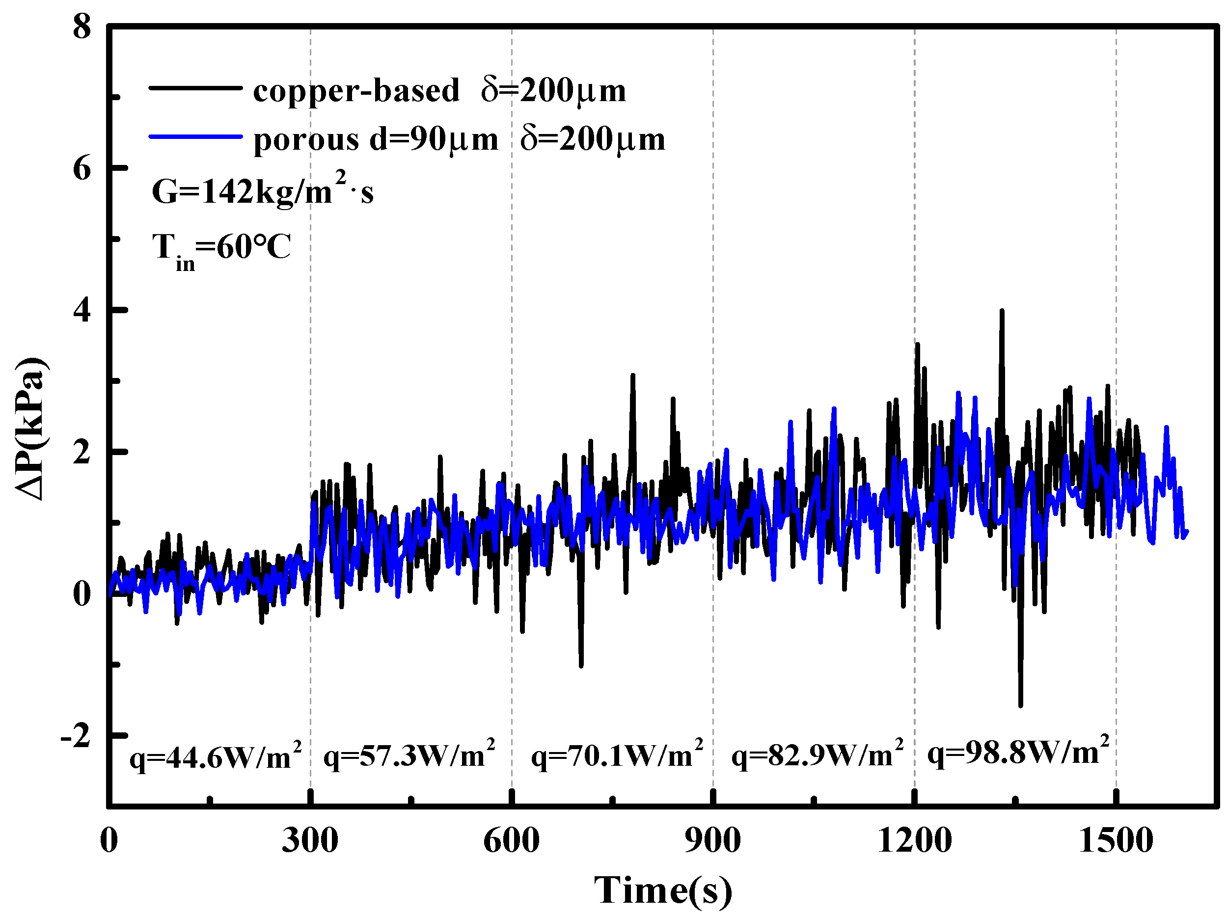
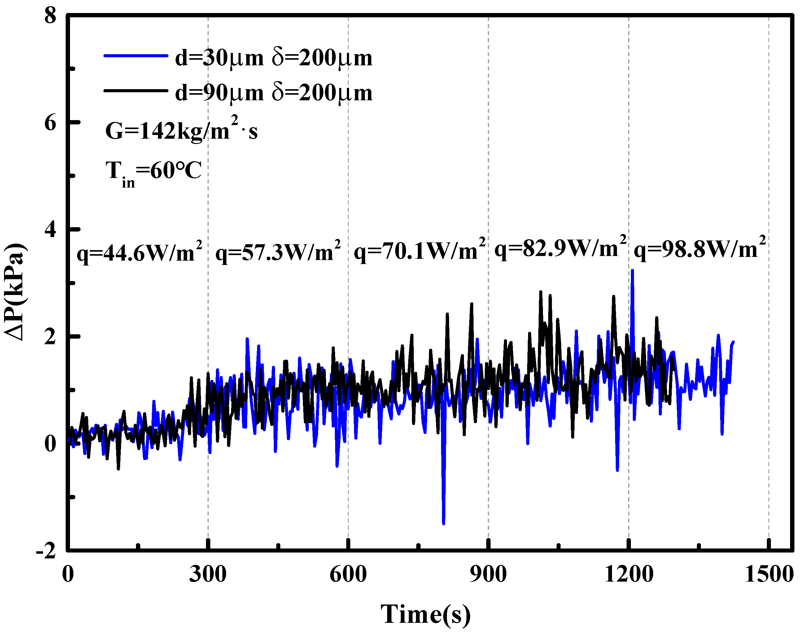
5. Two-Phase Flow Instability of Porous Microchannel
6. Conclusions
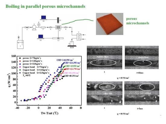
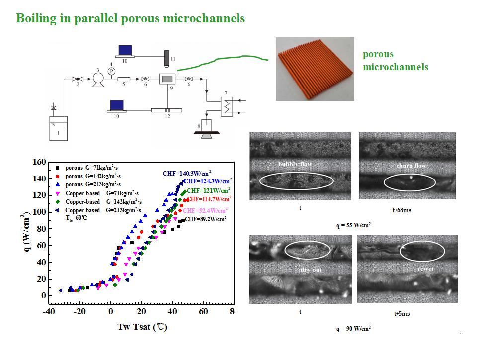
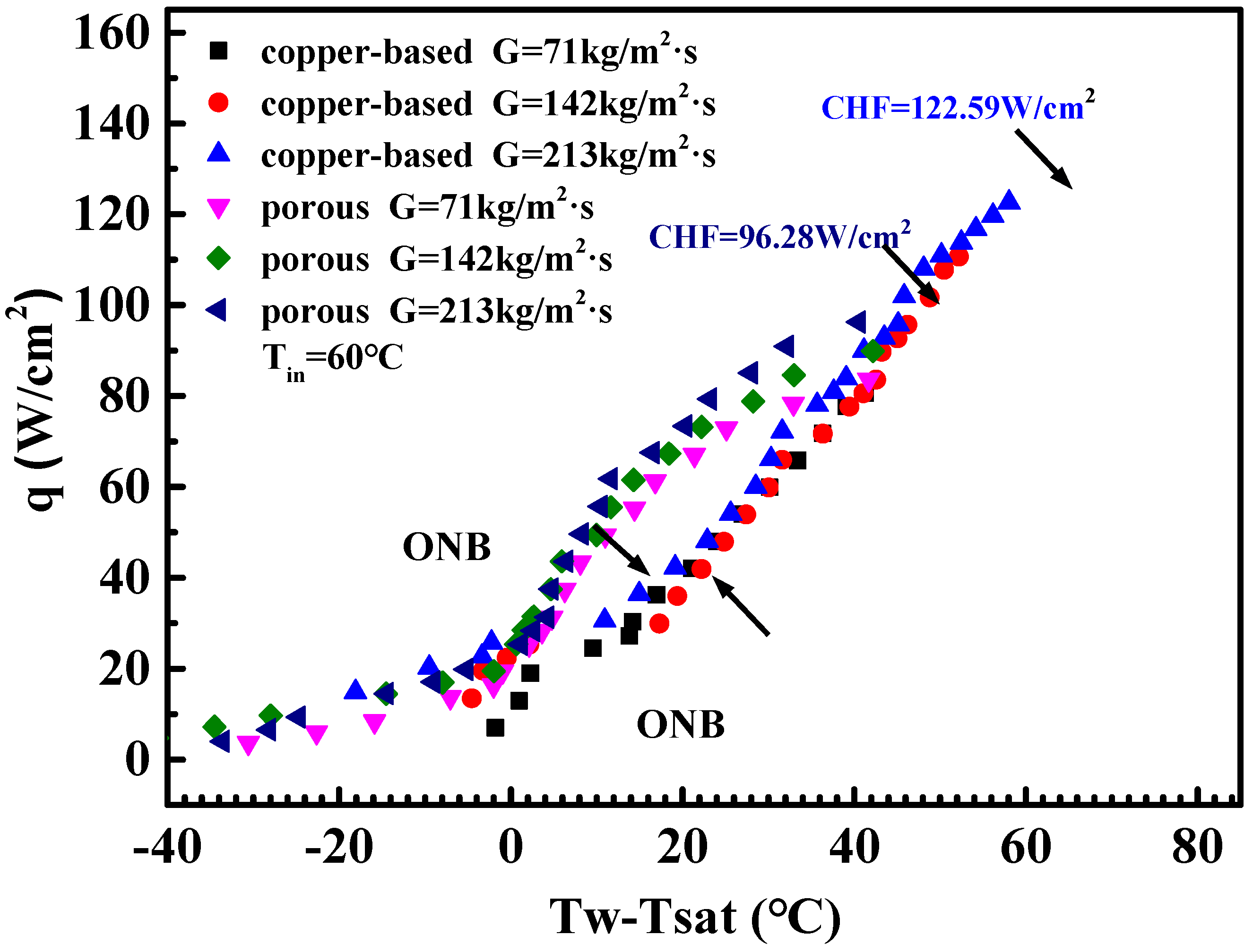
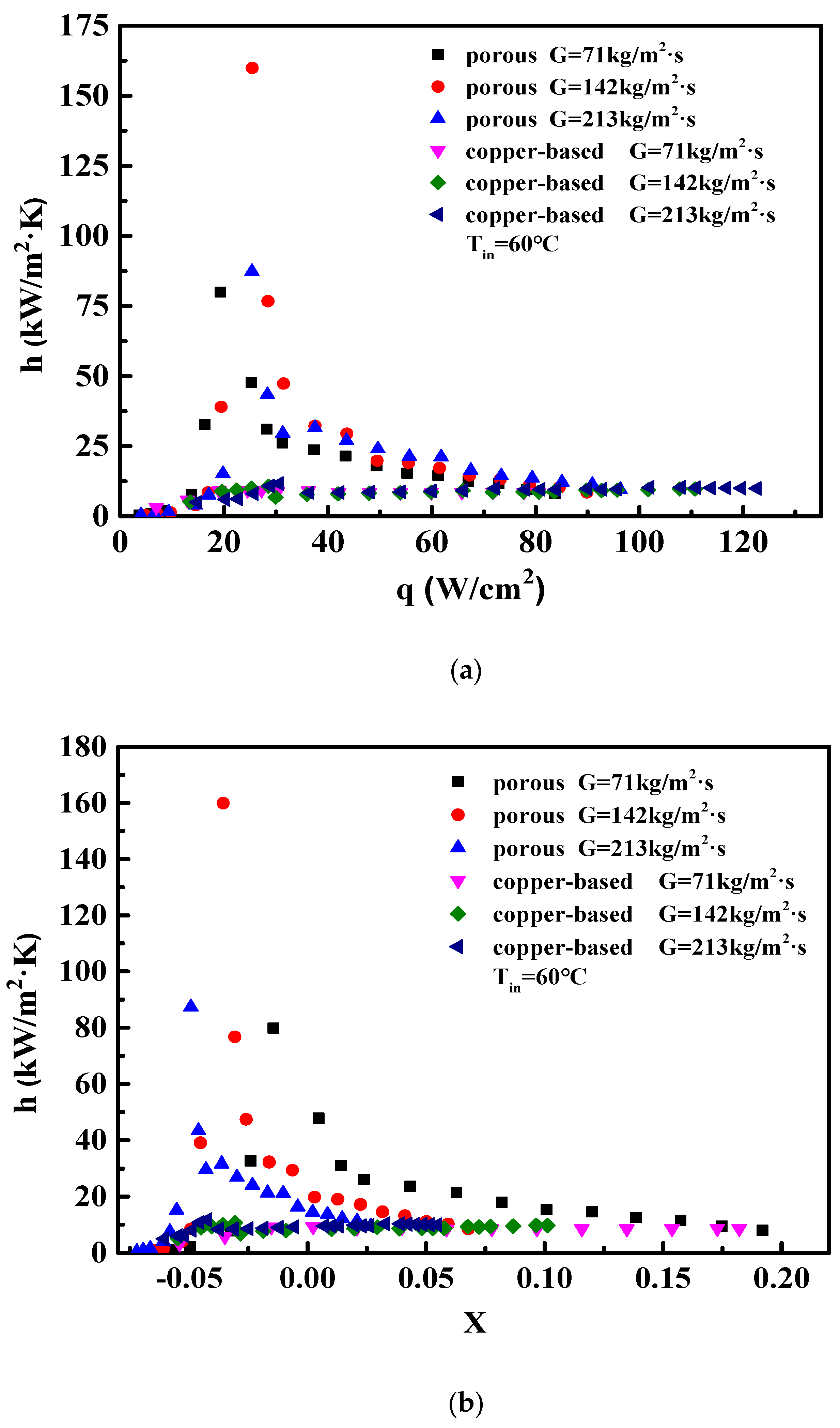
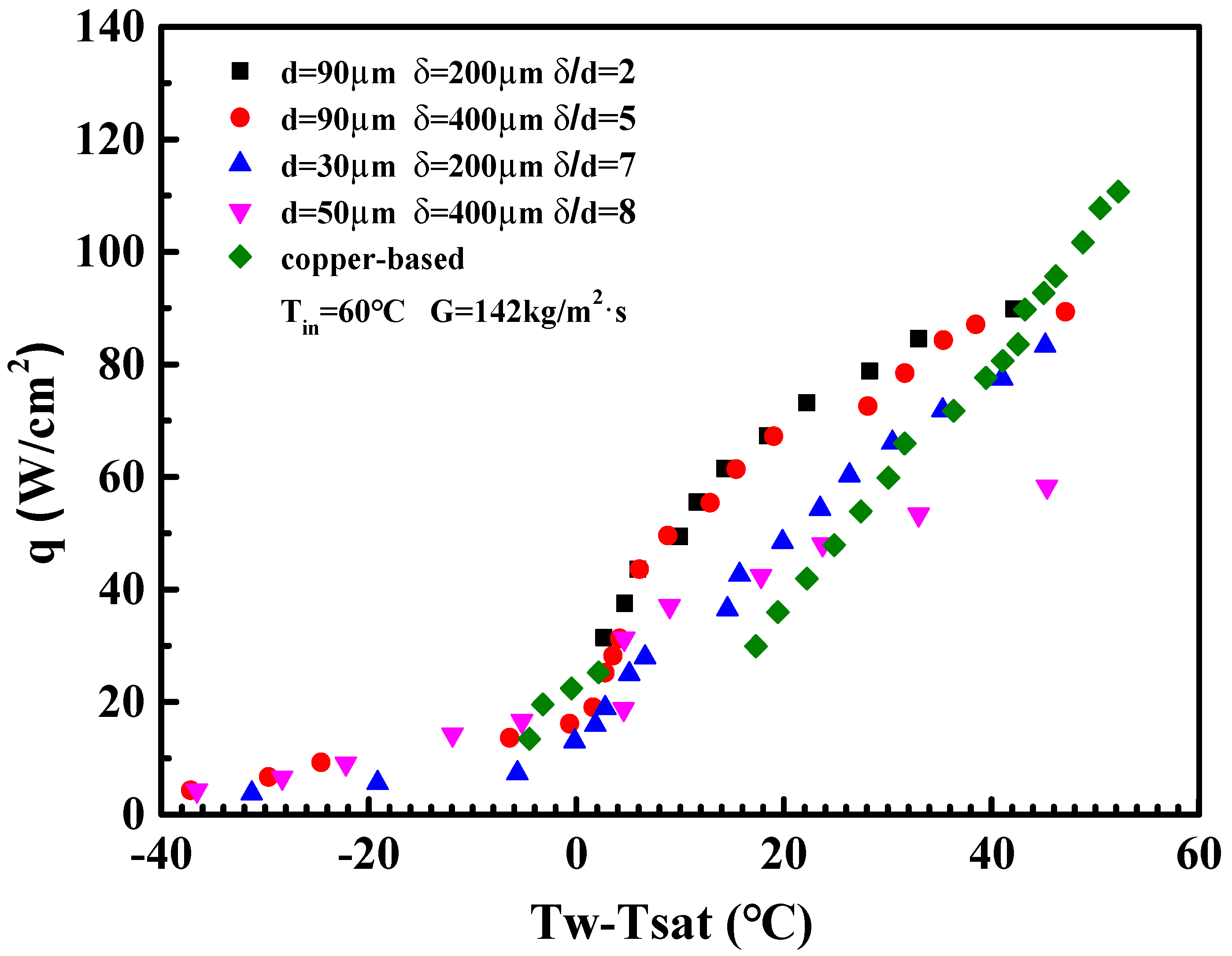
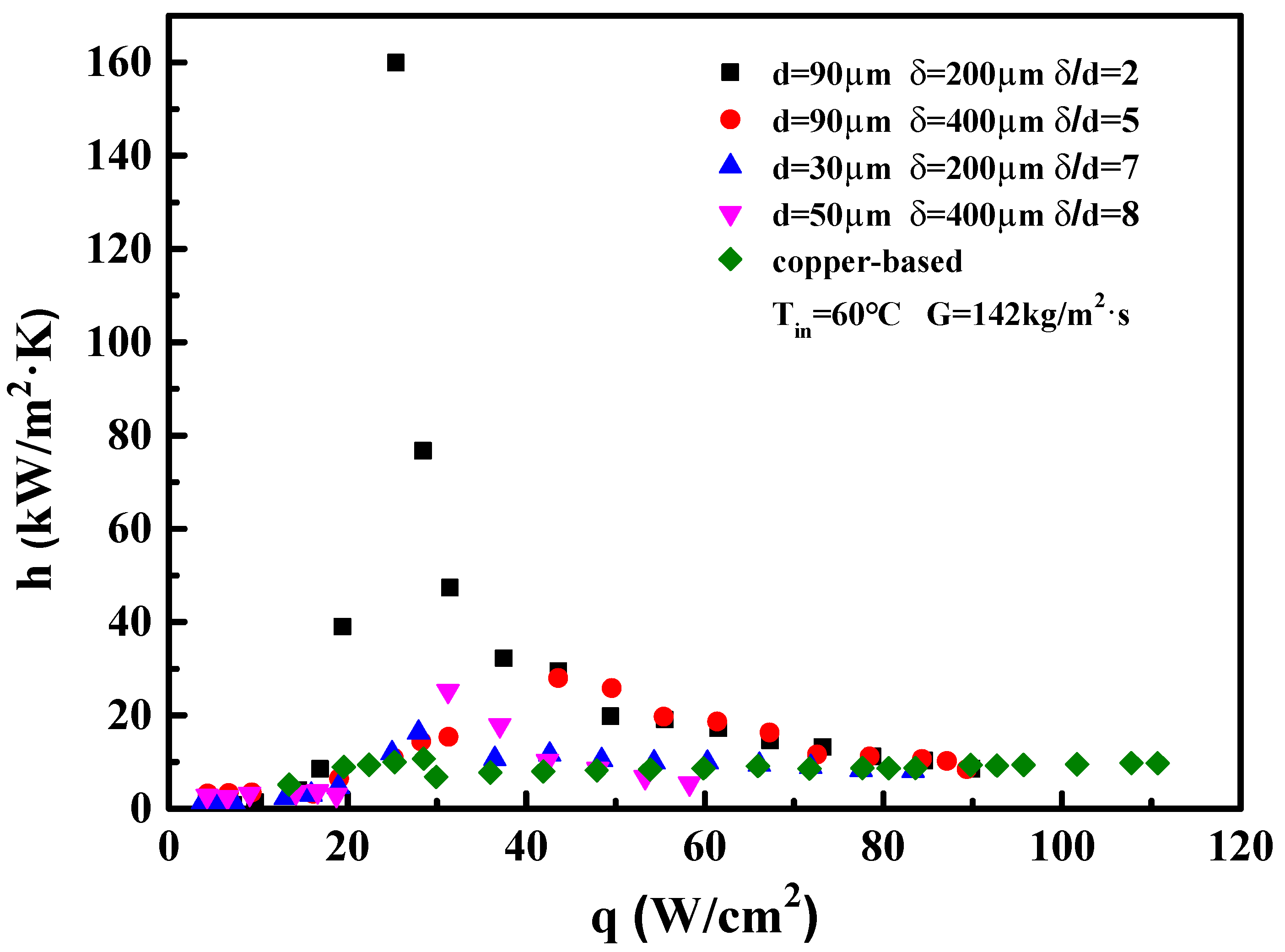
- The wall superheats for the boiling incipience in porous microchannels were much lower than in the copper-based one. The HTC of the porous microchannel was significantly higher than that of the copper-based microchannel at low and moderate heat fluxes. At high heat flux, the heat transfer performance of the porous samples approached that of the copper-based microchannel.
- The boiling heat transfer mechanism in the porous microchannel was mainly governed by the nucleate boiling mode, and the HTC was determined only by heat flux under low and moderate heat flux. Up to high flux condition, the heat transfer mechanism in the porous microchannel was converted into convection boiling mode; thus, the HTCs were dependent on both the flow velocity and heat flux.
- The optimal thickness-to-particle-size ratio ranged between 2–5 for porous microchannels. As the δ/d was further increased up to 7, the enhancing effect of the porous microchannel became degraded.
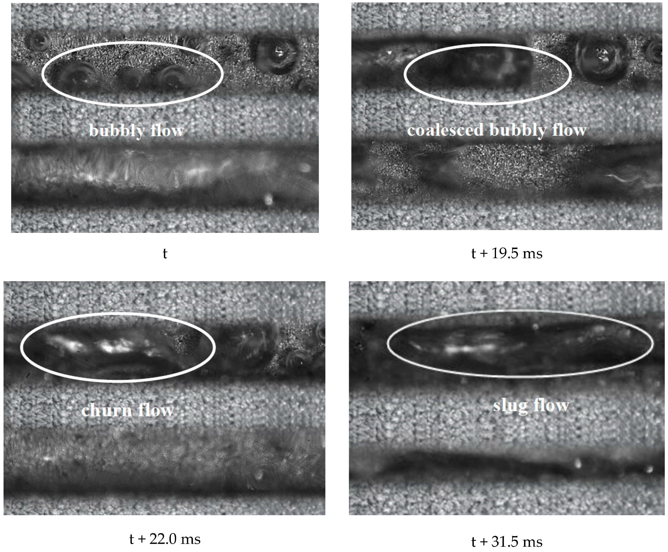
- The porous microchannel could suppress the flow fluctuation from low to moderate heat fluxes. The bubble coalescence effects in porous microchannels were less than in the copper-based microchannel. Porous microchannels were helpful to establish a stable nucleate boiling process; this was the typical mechanism for the porous microchannel to alleviate the flow fluctuation.
Author Contributions
Funding
Conflicts of Interest
Nomenclature
| dchannel | Hydraulic diameter, m |
| qeff | Effective heat flux, W/cm2 |
| d | Particle diameter, mm |
| Qtotal | Total input heat power, W |
| L | Length of microchannel, cm |
| Qeff | Effective input heat power, W |
| N | Microchannel numbers |
| Qloss | Heat loss, W |
| G | Mass flux, kg/m2·s |
| CHF | Critical heat flux, W |
| ΔTsup | Wall superheat, K |
| ΔTsub | Degree of liquid subcooling, K |
| Tin | Inlet temperature, °C |
| Mass flow rate, kg/s | |
| Tsat | Saturation temperature, °C |
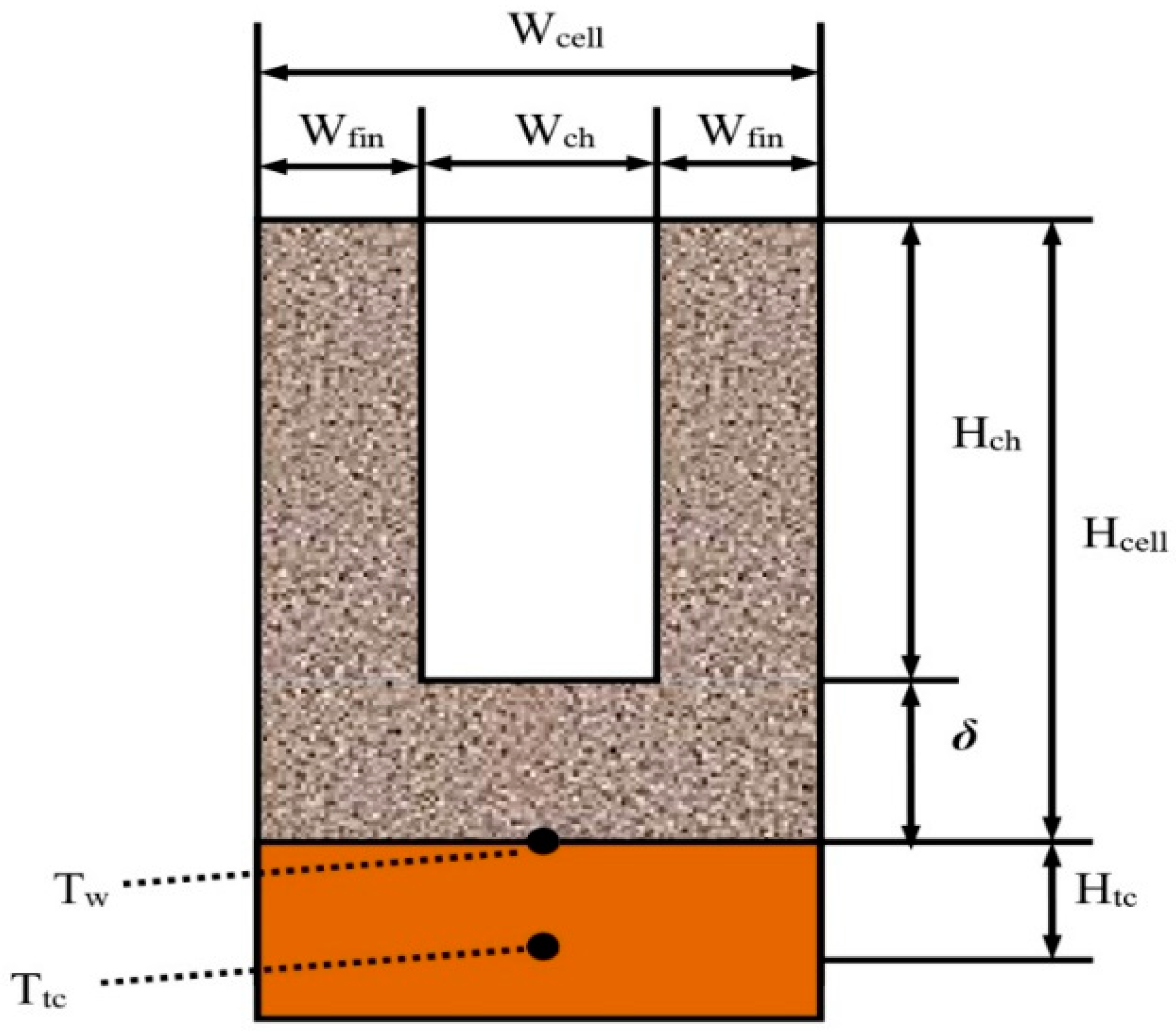
| δ | Sintering thickness, mm |
| Pin | Inlet fluid pressure, kpa |
| x | Vapor quality |
| Pout | Outlet fluid pressure, kpa |
| λ | Thermal conductivity, W/m·K |
| ΔP | Pressure drop, Pa |
| Ach | Cross-section area of the single |
| h | Heat transfer coefficient |
| hfg | Latent heat of vaporization, kj/kg |
| Abase | Top surface area of the copper block, cm2 |
| ONB | Onset of nucleation boiling |
| HTC | Heat transfer coefficient, kw/m2·K |
| Hcell | Depth of porous unit cell, μm |
| Wcell | Width of porous unit cell, μm |
| Hch | Depth of microchannel, μm |
| Wch | Width of microchannel, μm |
| Wfin | Width of microchannel fin, μm |
| Subscripts | |
| ν | Vapor phase |
| l | Liquid phase |
References
- Przemysław, S.; Sławomir, P. A review of the capabilities of high heat flux removal by porous materials, microchannels and spray cooling techniques. Appl. Therm. Eng. 2016, 104, 636–646. [Google Scholar]
- Prajapati, Y.K.; Bhandari, P. Flow boiling instabilities in microchannels and their promising solutions—A review. Exp. Therm. Fluid Sci. 2017, 88, 576–593. [Google Scholar]
- Cheng, P.; Wu, H.Y. Mesoscale and microscale phase-change heat transfer. Adv. Heat Transf. 2006, 39, 469–573. [Google Scholar]
- Jaikumar, A.; Kandlikar, S. Enhanced pool boiling for electronics cooling usingporous fin tops on open microchannels with FC-87. Appl. Therm. Eng. 2015, 91, 426–433. [Google Scholar] [CrossRef] [Green Version]
- Zhuan, R.; Wang, W. Boiling heat transfer characteristics in a minichannel array heat sink with low mass flow rate. Appl. Therm. Eng. 2013, 51, 65–74. [Google Scholar] [CrossRef]
- Kumar, C.S.; Kumar, G.U.; Arenales, M.R.; Hsu, C.C. Elucidating the mechanisms behind the boiling heat transfer enhancement using nano-structured surface coatings. Appl. Therm. Eng. 2018, 137, 868–891. [Google Scholar] [CrossRef]
- Law, M.; Lee, P.S. A comparative study of experimental flow boiling heat transfer and pressure characteristics in straight- and oblique-finned microchannels. Int. J. Heat Mass Transf. 2015, 85, 797–810. [Google Scholar] [CrossRef]
- Xu, J.L.; Yu, X.G.; Wu, J. Porous-wall microchannels generate high frequency eye-blinking interface oscillation, yielding ultra stable wall temperatures. Int. J. Heat Mass Transf. 2016, 101, 341–353. [Google Scholar] [CrossRef]
- Kuo, C.J.; Peles, Y. Local Measurement of flow boiling in structured surface microchannels. Int. J. Heat Mass Transf. 2007, 50, 4513–4526. [Google Scholar]
- Kim, D.E.; Yu, D.Y.; Jerng, D.W.; Kim, M.H.; Ahn, H.S. Review of boiling heat transfer enhancement on micro/nanostructured surfaces. Exp. Therm. Fluid Sci. 2015, 66, 173–196. [Google Scholar] [CrossRef]
- Jun, S.; Kim, J.; Son, D.; Kim, H.Y. Enhancement of pool boiling heat transfer in water using sintered copper microporous coatings. Nucl. Eng. Technol. 2016, 48, 932–940. [Google Scholar]
- Kumar, C.S.; Suresh, S.; Yang, Q.; Aneesh, C.R. An experimental investigation on flow boiling heat transfer enhancement using spray pyrolysed alumina porous coatings. Appl. Therm. Eng. 2014, 71, 508–518. [Google Scholar]
- Chang, J.Y.; You, S.M. Heater orientation effects on pool boiling of micro-porous enhanced surfaces in saturated FC-72. J. Asme Heat Transf. 1996, 118, 937–943. [Google Scholar] [CrossRef]
- Yang, C.Y.; Liu, C.F. Effect of coating layer thickness for boiling heat transfer on micro porous-coated surface in confined and unconfined spaces. Exp. Therm. Fluid Sci. 2013, 47, 40–47. [Google Scholar] [CrossRef]
- Sun, Y.; Zhang, L.; Xu, H. Subcooled flow boiling heat transfer from micro-porous surfaces in a small channel. Int. J. Therm. Sci. 2011, 50, 881–889. [Google Scholar]
- Srikar, V.; Peles, Y.; Leonel, R. Self-assembly of micro- and nanoparticles on internal micromachined silicon surfaces. Sens. Actuators A 2004, 113, 124–131. [Google Scholar]
- Bai, P.; Tang, T.; Tang, B. Enhanced flow boiling in parallel microchannels with metallic porous coating. Appl. Therm. Eng. 2013, 58, 291–297. [Google Scholar] [CrossRef]
- Sheng, C.C. Flow Boiling Heat Transfer Enhancement in Microchannel Evaporator. Ph.D. Thesis, National Taiwan University (Director: Chen Yau-Ming), Taipei City, Taiwan, 2012. [Google Scholar]
- Daxiang, D.; Ruxiang, C.; Yong, T. A comparative study of flow boiling performance in reentrant copper microchannels and reentrant porous microchannels with multi-scale rough surface. Int. J. Multiph. Flow 2015, 72, 275–287. [Google Scholar]
- Chen, J.; Zhang, S.; Tang, Y.; Chen, H.; Yuan, W.; Zeng, J. Effect of operational parameters on flow boiling heat transfer performance for porous interconnected microchannel nets. Appl. Therm. Eng. 2017, 121, 443–453. [Google Scholar] [CrossRef]
- Deng, D.; Tang, Y. Flow boiling characteristics in porous heat sink with reentrant microchannels. Int. J. Heat Mass Transf. 2014, 70, 463–477. [Google Scholar] [CrossRef]


| Parameters | Materials |
|---|---|
| Thermocouple | ±0.5 K |
| Pt100 | ±0.3 K |
| Flow rate | ±4% |
| Pressure | ±0.25% |
| Heat power Q | ±0.5% |
| Thickness of solder (0.2 mm) | ±3% |
| Thermal conductivity of solder (50 W/m·K) | ±3% |
| Heat loss | ±5% |
| Copper surface area | ±2% |
| Local saturated temperature Ts | ±0.5% |
| The distance of surface (0.75 cm) | ±5% |
| Wcell (1.2 mm) and Wch (0.6 mm) | ±3% |
| Hch (1.2 mm) | ±4% |
| Wall temperature | ±1–2% |
| Effective heat flux | ±5% |
| Pressure drop | ±0.35% |
| Heat transfer coefficient | ±13.3–40.0% |
| Width, Wch (μm) | Depth, Hch (μm) | Wall Thickness, Wfin (μm) | Hydraulic Diameter, dh (μm) | Number of Trenches N |
|---|---|---|---|---|
| 600 | 1200 | 600 | 800 | 23 |
| Sample | ParticleSize, d (μm) | Sintering Thickness, δ (μm) | Sintering Temperature (℃) | δ/d |
|---|---|---|---|---|
| 1 | 30 | 200 | 900 | 7 |
| 2 | 50 | 400 | 900 | 8 |
| 3 | 90 | 200 | 900 | 2 |
| 4 | 90 | 400 | 900 | 5 |
© 2020 by the authors. Licensee MDPI, Basel, Switzerland. This article is an open access article distributed under the terms and conditions of the Creative Commons Attribution (CC BY) license (http://creativecommons.org/licenses/by/4.0/).
Share and Cite
Zhang, D.; Xu, H.; Chen, Y.; Wang, L.; Qu, J.; Wu, M.; Zhou, Z. Boiling Heat Transfer Performance of Parallel Porous Microchannels. Energies 2020, 13, 2970. https://doi.org/10.3390/en13112970
Zhang D, Xu H, Chen Y, Wang L, Qu J, Wu M, Zhou Z. Boiling Heat Transfer Performance of Parallel Porous Microchannels. Energies. 2020; 13(11):2970. https://doi.org/10.3390/en13112970
Chicago/Turabian StyleZhang, Donghui, Haiyang Xu, Yi Chen, Leiqing Wang, Jian Qu, Mingfa Wu, and Zhiping Zhou. 2020. "Boiling Heat Transfer Performance of Parallel Porous Microchannels" Energies 13, no. 11: 2970. https://doi.org/10.3390/en13112970