Article

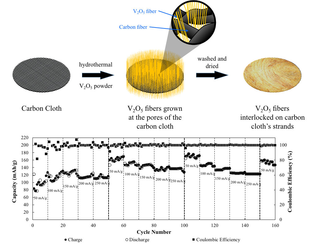
Binder-Free Centimeter-Long V2O5 Nanofibers on Carbon Cloth as Cathode Material for Zinc-Ion Batteries

by
Lyn Marie De Juan-Corpuz
1,2,3,
Ryan Dula Corpuz
1,
Anongnat Somwangthanaroj
1,
Mai Thanh Nguyen
4,
Tetsu Yonezawa
4,5,
Jianmin Ma
6,7,* and
Soorathep Kheawhom
1,8,*
1
Department of Chemical Engineering, Faculty of Engineering, Chulalongkorn University, Bangkok 10330, Thailand
2
Research Center for the Natural and Applied Sciences, University of Santo Tomas, Manila 1015, Philippines
3
Department of Chemical Engineering, Faculty of Engineering, University of Santo Tomas, Manila 1015, Philippines
4
Division of Materials Science and Engineering, Faculty of Engineering, Hokkaido University, Hokkaido 060-8628, Japan
5
Institute of Business-Regional Collaborations, Hokkaido University, Hokkaido 001-0021, Japan
6
School of Physics and Electronics, Hunan University, Changsha 410082, China
7
Key Laboratory of Materials Processing and Mold, Ministry of Education, Zhengzhou University, Zhengzhou 450002, China
8
Research Unit of Advanced Materials for Energy Storage, Chulalongkorn University, Bangkok 10330, Thailand
*
Authors to whom correspondence should be addressed.
Energies 2020, 13(1), 31; https://doi.org/10.3390/en13010031
Submission received: 19 November 2019 / Revised: 15 December 2019 / Accepted: 18 December 2019 / Published: 19 December 2019
(This article belongs to the Collection Advanced Materials for Energy Conversion and Storage Devices)

Abstract

:
Recently, rechargeable aqueous zinc-ion batteries (AZBs) have attracted extensive interest due to their safety, abundance, low cost, and low toxicity. However, aqueous electrolytes require a polymeric binder to prevent dissolution of the active material in addition to its binding properties. This study highlights binder-free, centimeter long, single-crystal, V2O5 nanofibers (BCS-VONF) on carbon cloth, as the cathode material for AZBs synthesized via a simple one-step hydrothermal process. BCS-VONF in 3.0 M Zn(OTf)2 exhibit promising electrochemical performance with excellent capacity retention. Even in the absence of a binder, BCS-VONF were found to be very stable in 3.0 M Zn(OTf)2. They will not yield to the dissolution and detachment of the active material on the current collector. The novel strategy described in this study is an essential step for the development of BCS-VONF on carbon cloth, as a promising cathode material for AZBs.

Graphical Abstract

1. Introduction

Sustainable and renewable energy sources, e.g., solar, wind, geothermal, biomass, and hydropower, have gathered much attention for their ability to mitigate global environmental issues. However, solar and wind energies have intermittent operations due to geographical and environmental conditions [1,2,3]. To effectively utilize these renewable energies, electrical energy storage devices (EES) are necessary. Among the available EES, the lithium-ion battery (LIB) serves as the forerunner due to its versatility and wide range of applications. Yet, LIBs show several shortcomings such as safety issues, transportation restrictions, aging, recycling, and most especially, the cost and limited abundance of the material [4,5,6]. The safety issue is associated with the flammable organic electrolyte and hence aqueous rechargeable batteries have been considered as a promising alternative due to their environmental friendliness, high safety, and less rigorous and sensitive manufacturing conditions [7]. Compared to lithium-based technologies which use organic electrolytes, aqueous electrolytes are much safer, cheaper, easier to scale up, and have superior volumetric capacity [8,9]. In addition, aqueous electrolytes have higher ionic conductivity (~1 S cm−1) compared to their non-aqueous counterparts (~1 mS cm−1) favoring high rate capability [7,10]. Among the different negative electrode materials used in aqueous batteries, Zn, which has low redox potential and high stability in water (high overpotential for hydrogen evolution that allows zinc stripping and deposition highly reversible), are particularly promising [11]. The redox potential of Zn is −0.763 V vs. standard hydrogen potential (SHE). Hence, it is more suitable for an aqueous electrolyte with the implementation of near neutral or slightly acidic electrolytes [12]. Moreover, since Zn is environmentally (air and moisture) insensitive, an aqueous zinc-ion battery (AZB) enables easier and cheaper processing for fabrication and packaging [13,14]. Thus, sophisticated equipment to maintain the inert manufacturing environment is no longer needed. In addition, Zn has a higher specific volumetric capacity compared to that of Li viz. 5855 mAh cm−3 and 2066 mAh cm−3, respectively [15], is lower in cost (~$0.9 lb−1) and highly abundant (~300 times higher than Li in the Earth’s crust) [16,17].
Several cathodes have been utilized for AZBs e.g., Prussian blue analogues [18,19,20], metal oxides (manganese and vanadium) [21,22,23], and zinc salts (ZnxMyOz) where M is manganese (Mn) or vanadium (V) [24,25], and where the storage mechanism of Zn2+ can either be conversion or intercalation mechanism. Intercalation compound provides the benefits of topotactic reaction that minimizes the changes in the structure and hence the large volumetric change [26]. The insertion kinetics of Zn2+ in metal oxides are very sluggish due to a large solvation sheath and high charge/radius ratio of Zn2+ even though the radius of Zn2+ (0.074 nm) is close to that of Li+ (0.068 nm). Hence, V2O5•H2O with large interlayer spacing and MnO2 polymorphs with unique tunnel are favorable to store zinc ions [8]. Vanadium oxide-based cathodes show much promise, having a high specific discharge capacity and long cyclability [23]. In addition, vanadium-based compounds have multiple oxidation states [27,28,29]. Kundu et al. [26] reported the intercalation of Zn2+ ions in layered V3O7•H2O for AZB. Based on their in-operando X-ray diffraction (XRD) and impedance result, the solid solution behavior of Zn2+ ions is via diffusion within a water monolayer in the interlayer gap. Ding et al. [8] studied the intercalation pseudocapacitance behavior and ultrafast kinetics of Zn2+ into the unique tunnels of VO2 nanofibers in AZBs. The unique tunnel transport pathways with dimensions of 0.82 and 0.5 nm2 along the b- and c-axis, and the small structural change of Zn2+ intercalation, eliminates the limitation from the solid-state diffusion in the vanadium dioxide. Qin et al. [30] used VS4@rGO as the cathode material for AZBs. The peculiar crystallographic structure of VS4 and the superior conductivity of rGO results in a good capacity retention of 93.3% after 165 cycles at a current density of 1 A g−1. Zhang et al. [7], on the other hand, elucidate the Zn-storage mechanism in the V2O5 cathode, where the (de)intercalated Zn2+ is hydrated. The co-intercalated H2O is observed to shield the electrostatic interactions between Zn2+ and the host framework, hence enhance the kinetics. Among various vanadium-based oxides, anhydrous vanadium pentoxide (V2O5) holds great potential as a cathode material for AZBs, due to its high theoretical capacity, i.e., 589 mA h g−1, which is based on the two-electron redox center (vanadium). However, according to Yin et al. [31], the magnitude of the sluggish diffusion in a material is greatly increased in the presence of an organic binder. Zn2+ possesses a higher charge density that can pose a polarizing effect on the material upon the diffusion process. Hence it tends to be adsorbed onto the C–F bonds in the polarizing polymeric binder. This results in reduced Zn2+ mobility and hence poor rate performance and large initial irreversible capacity loss. Hence, a binder-free electrode is favorable to ensure minimal disruption to the mobility of Zn2+ during the charge/discharge process. V2O5/CNT paper electrode delivered a specific capacity of 312 mA h g−1 with 75% retention in capacity after increasing the current density by tenfold. Their results showed that the absence of a binder results in a higher and more stable cathode material for AZBs.
Polymeric binders, namely poly(vinylidene fluoride) (PVDF), poly(tetrafluoroethylene) (PTFE), or carboxymethyl cellulose (CMC) are usually incorporated (~10%) in electrode preparation to attach the active material and conductive agent on the current collector. However, minimizing the amount of additives and binders is becoming attractive to attain a high mass loading of active material in the battery. Additives and binders add to the total weight of the battery. Also, polymeric binders increase processing and material costs due to the additional time needed to incorporate binders. Further, it is evident that PVDF utilizes a toxic solvent, N-methyl-2-pyrrolidone (NMP), which is not desirable [31,32,33,34]. Huang et al. [32] utilized a binder-free MnO2/rGO electrode as cathode material for AZBs. According to their study, the binder-free MnO2/rGO showed enhanced capacity, excellent rate capability and cycling stability in comparison to that of the conventional MnO2 electrode, i.e., with 20% Super-P and 10% PVDF. On the other hand, Jiao et al. [34] examined a binder-free hierarchical VS2 electrode for high performance AZBs towards commercial level mass loading, i.e., ~11 mg cm−2. The battery exhibited an excellent Zn ion storage capacity of 198 mA h g−1 and stable cycling performance, i.e., above 80% capacity retention over 2000 cycles at 2 A g−1.
Herein, this study is the first to investigate binder-free, centimeter long, single-crystal, V2O5 nanofibers (BCS-VONF) in AZBs since V2O5 is known to be soluble in water (8.0 L g−1 at 20 °C). It was found that by utilizing 3.0 M Zn trifluoromethanesulfonate (Zn(OTf)2 or Zn(CF3SO3)2), the dissolution of BCS-VONF can be prevented, and hence stability was achieved with promising electrochemical properties of BCS-VONF, as the cathode material for AZBs, in the absence of a polymeric binder.

2. Materials and Methods

2.1. Carbon Cloth Preparation

Carbon cloth (AvCarb 1071 HCB, AvCarb Material Solutions, USA) with dimensions of 3.5 × 8.5 cm was pre-treated by soaking it in 1.0 M sulfuric acid (H2SO4, Sigma-Aldrich, St. Louis, Missouri, USA) for 1 h. After treatment, the carbon cloth was washed several times with deionized (DI) water before it was placed at the inside wall of the Teflon container of the autoclave.

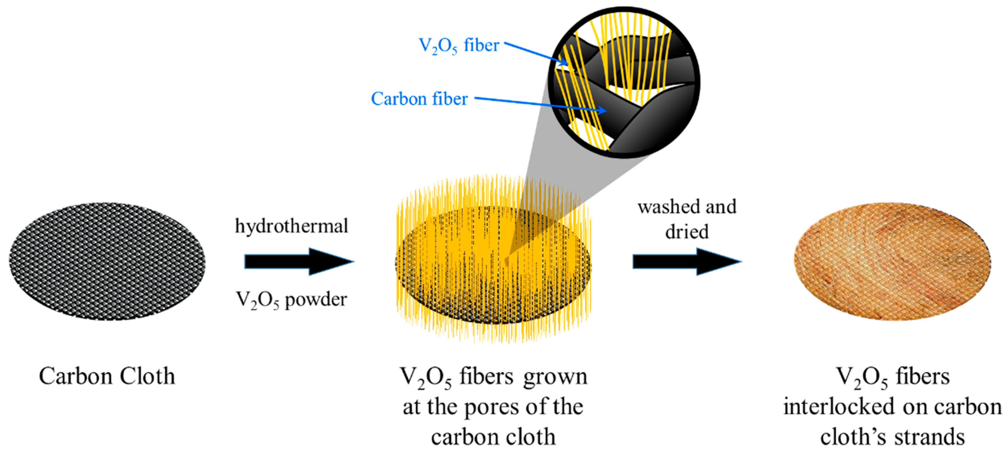
2.2. Synthesis of BCS-VONF

In a typical procedure, 0.36 g of vanadium (V) oxide (V2O5, Sigma-Aldrich, St. Louis, Missouri, USA), was added to 60 mL DI water. The solution was rapidly stirred for 5 min. Then, 5 mL hydrogen peroxide (H2O2, 30 w/w%, Merck KGaA, Germany) was added to the above solution and rapidly stirred for 1 h. Consequently, a noticeable change in color from orange to reddish orange took place, and a transparent orange was duly observed. Thereafter, the solution was transferred to a 100 mL Teflon-lined autoclave containing carbon cloth which was subsequently placed on a pre-heated oil bath at 180 °C and kept heated for 120 h. The solution was then allowed to cool at room temperature, i.e., 30 °C. The carbon cloth containing the golden yellow fibers was washed several times with DI water and isopropanol (QRëC, New Zealand). Finally, the sample was dried overnight at 70 °C under vacuum.

2.3. Materials Characterization

The morphology of the produced fibers was examined using scanning electron microscope (SEM, JEOL (USA) JSM-6480LV, 15 kV) and transmission electron microscope (TEM, JEOL (USA) JEM-1400, 100 kV). Both the crystalline and phase structure of the produced nanofibers were characterized using X-ray diffraction (Bruker (USA) D8-Advance, Cu Kα radiation, λ = 1.5418 Å) operating at 40 kV and 40 mA within a 2θ range of (5 to 90) degrees. The oxidation states of V and the purity of the formed V2O5 were examined using X-ray photoelectron spectroscopy (XPS, Thermo Scientific, USA) with a monochromatic X-ray source (Al Kα).

2.4. Electrochemical Characterization

Electrochemical tests were conducted using a CR2032 cell. The directly grown BCS-VONF on carbon cloth was punched into a disc (Ø = 15 mm) and was used as the positive electrode. Zn metal foil (Shandong AME Energy Co. Ltd., China) (thickness 0.08 mm, Ø = 15 mm) was used as the negative electrode. A glass microfiber filter (Whatman, Sigma-Aldrich, USA) was punched into a disc (Ø = 19 mm) and served as separator. As the electrolyte, 3.0 M zinc trifluoromethanesulfonate (Zn(CF3SO3)2 or Zn(OTf)2, 98%, Sigma-Aldrich, St. Louis, Missouri, USA) aqueous solution, 3.0 M Zn Sulfate (ZnSO4, QRëC, New Zealand) and 3.0 M Zn Chloride (ZnCl2, QRëC, New Zealand) were used. A galvanostatic charge/discharge constant current test in the voltage range of 0.4 to 1.8 V was performed using a battery analyzer (NEWARE BTS-4000 series, Neware Technology Ltd., China).

3. Results and Discussion

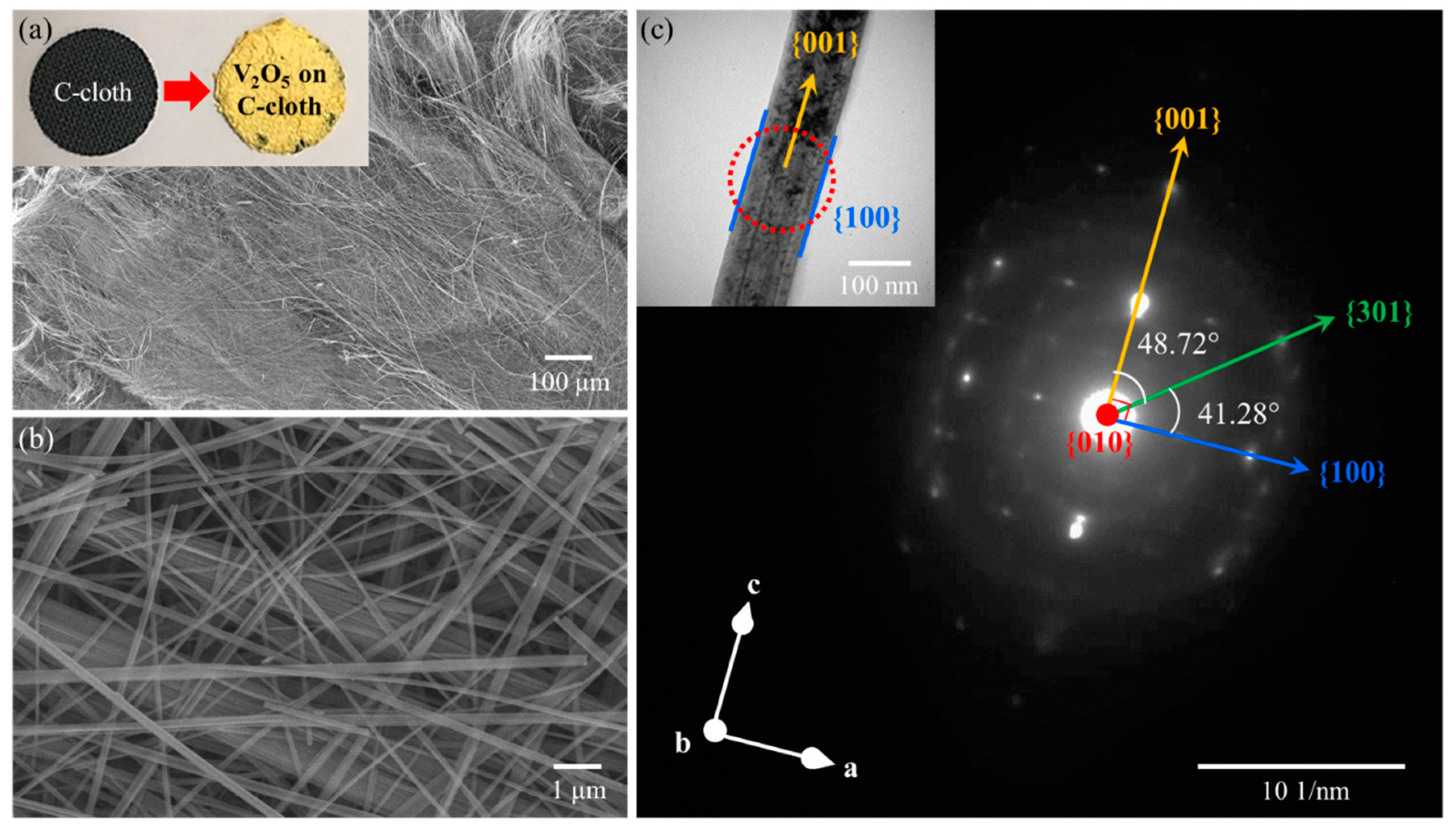
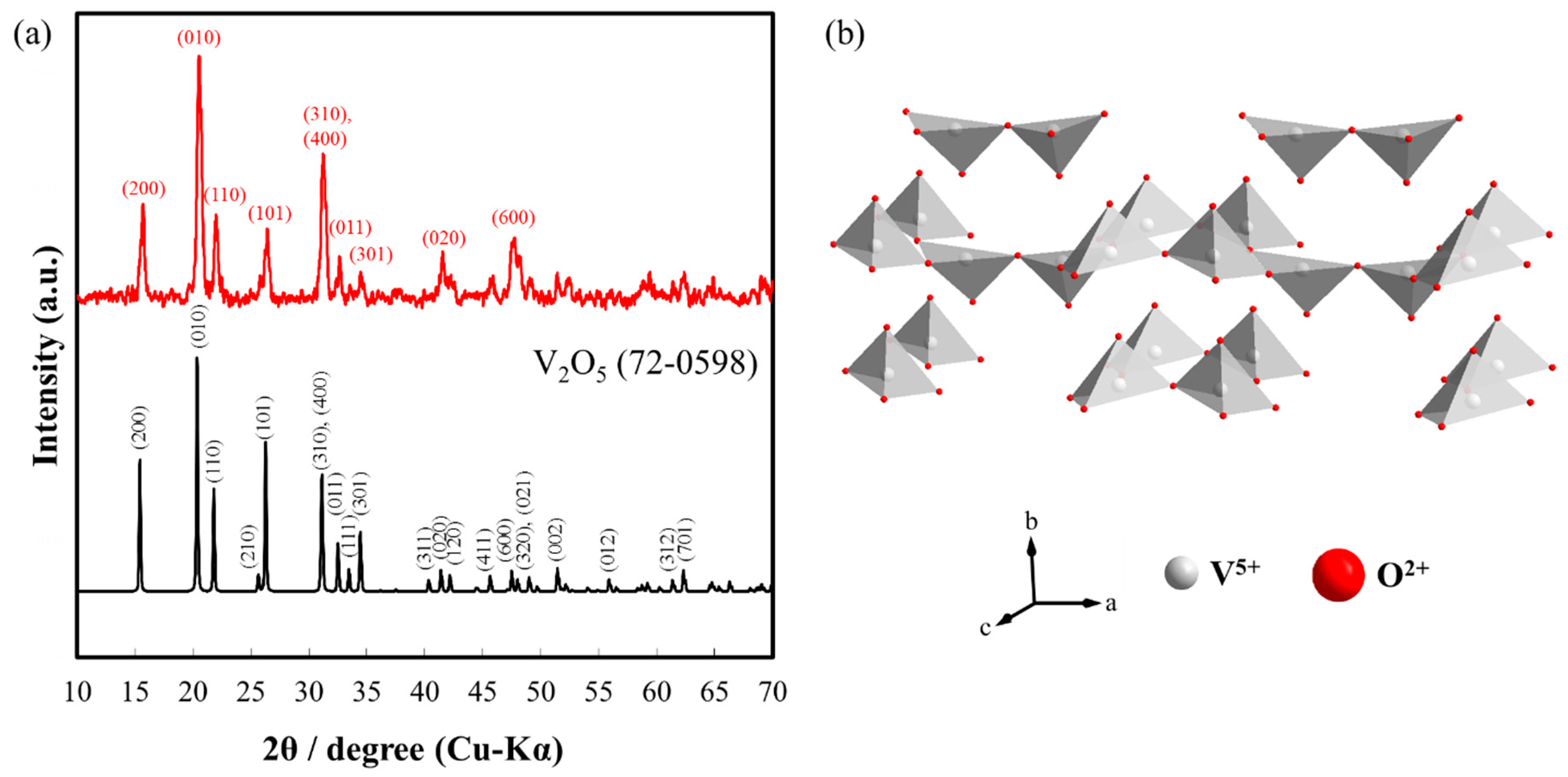
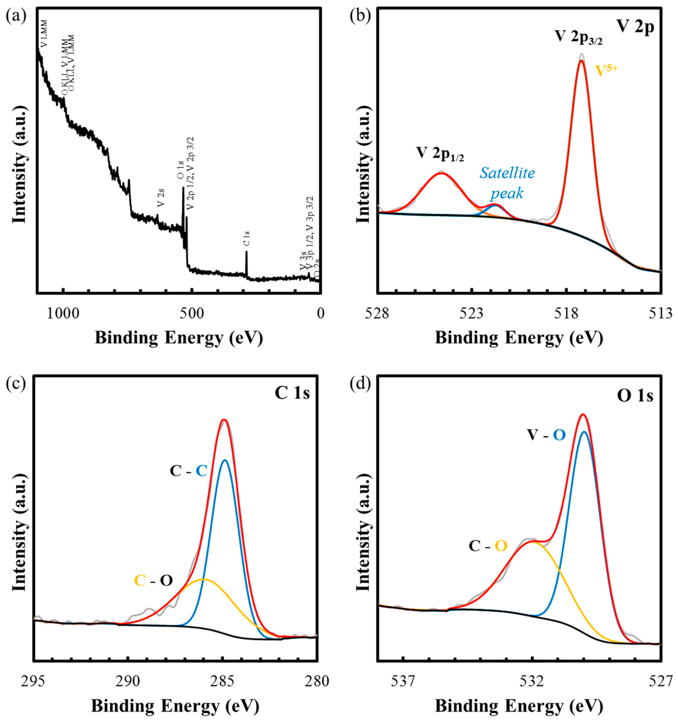
3.1. Characterization of BCS-VONF on Carbon Cloth

In the presence of hydrogen peroxide (H2O2), the morphology of vanadium oxide was transformed from powder to fibrous morphology via a simple one-step hydrothermal process. Incorporating carbon cloth during the hydrothermal process allows for the growth of vanadium oxide on carbon cloth in the absence of a binder, as indicated at the inset of Figure 1a. After the hydrothermal process, it can be seen that the yellowish vanadium oxide completely covered the surface of the carbon cloth with average mass loading of 3.19 ± 0.609 g cm−2. As illustrated in SEM images (Figure 1a,b), the produced vanadium oxide had a nanofiber morphology with diameters of (~100–200) nm. In addition, as shown in Figure S1, the length of the produced vanadium oxide is centimeter-long. In Figure S2, energy dispersive spectroscopy (EDS) analysis of the centimeter-long nanofibers is shown. Based on the EDS results, these nanofibers have an average atomic percentage of 28.98% V and 71.02% O which corresponds to V2O5, with a theoretical atomic percentage of 28.57% V and 71.43% O. These centimeter-long nanofibers were analyzed under TEM and selected area electron diffraction (SAED) (Figure 1c). As highlighted by the discrete spots, it can be observed that the fibers are single crystal. Due to its yellowish color (V5+), EDS analysis, and the diffracted pattern, it can be deduced that the formed nanofibers are vanadium pentoxide (V2O5). SAED results show that the V2O5 nanofibers grow along the <001> with {100} and {010} facets. These agree well with the Wulff constructed equilibrium shape of V2O5, as seen in Figure S3 where V2O5 has a belt-like morphology. The large surface corresponds to the lowest surface energy plane {010}, while both {100} and {001} with surface energies greater than {010} by an order of magnitude, were observed at the tip and sides of the particles, respectively [35].
XRD analysis was carried out to verify the existence of V2O5. Based on the XRD analysis (Figure 2a), the produced BCS-VONF (ICDD # 72-0598) are in good agreement with both the EDS and SAED results, as well as the yellowish color (presence of V5+) of the produced particles. It can also be observed that (200), (010), (400), (020), and (600) are more prominent with respect to other crystallographic planes. This phenomenon is attributed to the produced morphology where the centimeter-long nanofibers have {100} and {010} facets. The most intense peak viz. (010) can be ascribed to the large surface covered by {010} due to its low surface energy, as indicted by the Wulff constructed equilibrium shape of V2O5. In Figure 2b, the V2O5 structure consists of layers of VO5 square pyramids where the edges and corners are shared [36].
In Figure 3, the purity of the produced BCS-VONF was confirmed by XPS analysis. The wide scan spectrum, as in Figure 3a, demonstrates the presence of V, O, and C in the sample. The narrow scan spectrum of V 2p (Figure 3b) matches well with V5+, as indicated by the 2p3/2 and 2p1/2 at 517.2 eV and 524.61 eV, respectively, in the absence of other oxidation states of V [27,28]. The spin-orbit splitting between the measured 2p3/2 and 2p1/2 is 7.41 eV. This is in good agreement with the standard value of 7.4 eV for V2O5. It can also be noted that a satellite peak can be observed at 521.74 eV of the V 2p core spectra of pure V2O5 which can be attributed to the strong hybridization between V 3d and O 2p levels [37,38]. The deconvoluted peaks of O 1s (Figure 3c) at 529.96 eV and 531.91 eV correspond to V–O and C–O, respectively [27,28]. On the other hand, the deconvoluted peaks of C 1s (Figure 3d) at 284.86 eV and 285.86 eV can be attributed to C–C and C–O, respectively. The presence of C–O peaks is due to the surface oxidation of carbon cloth during the hydrothermal process in the presence of H2O2.
In Scheme 1, the growth and attachment of the BCS-VONF on carbon cloth, in the absence of a binder, is shown. When the carbon cloth was present during the hydrothermal process (transformation from V2O5 powder to BCS-VONF), the nanofibers grew at the pores of the carbon cloth and got entangled with other BCS-VONF and the fibers of the carbon cloth, due to its long length. Thus, the entangled wires allowed for greater attachment of BCS-VONF to the carbon cloth. Hence, the polymeric binders were no longer needed.

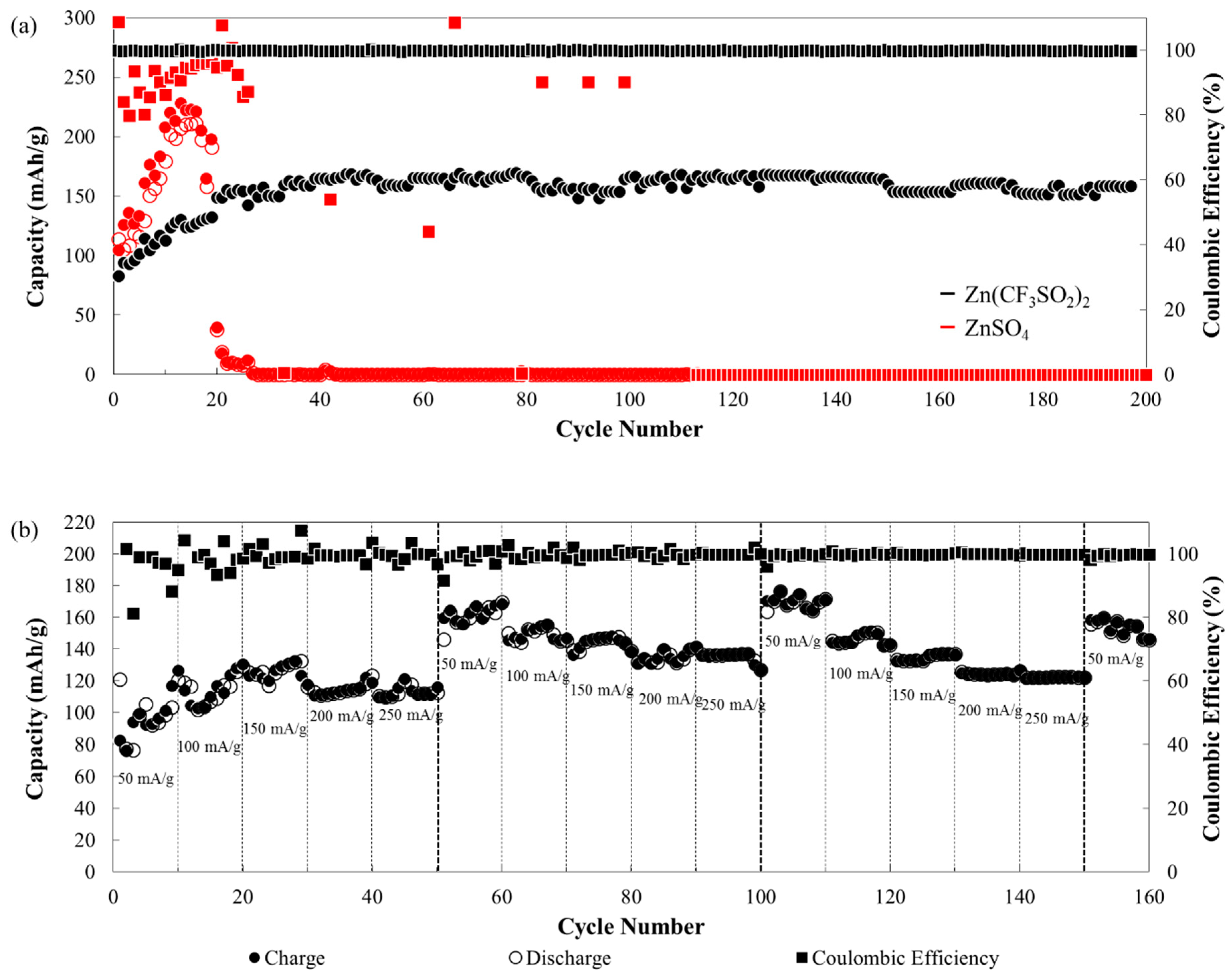
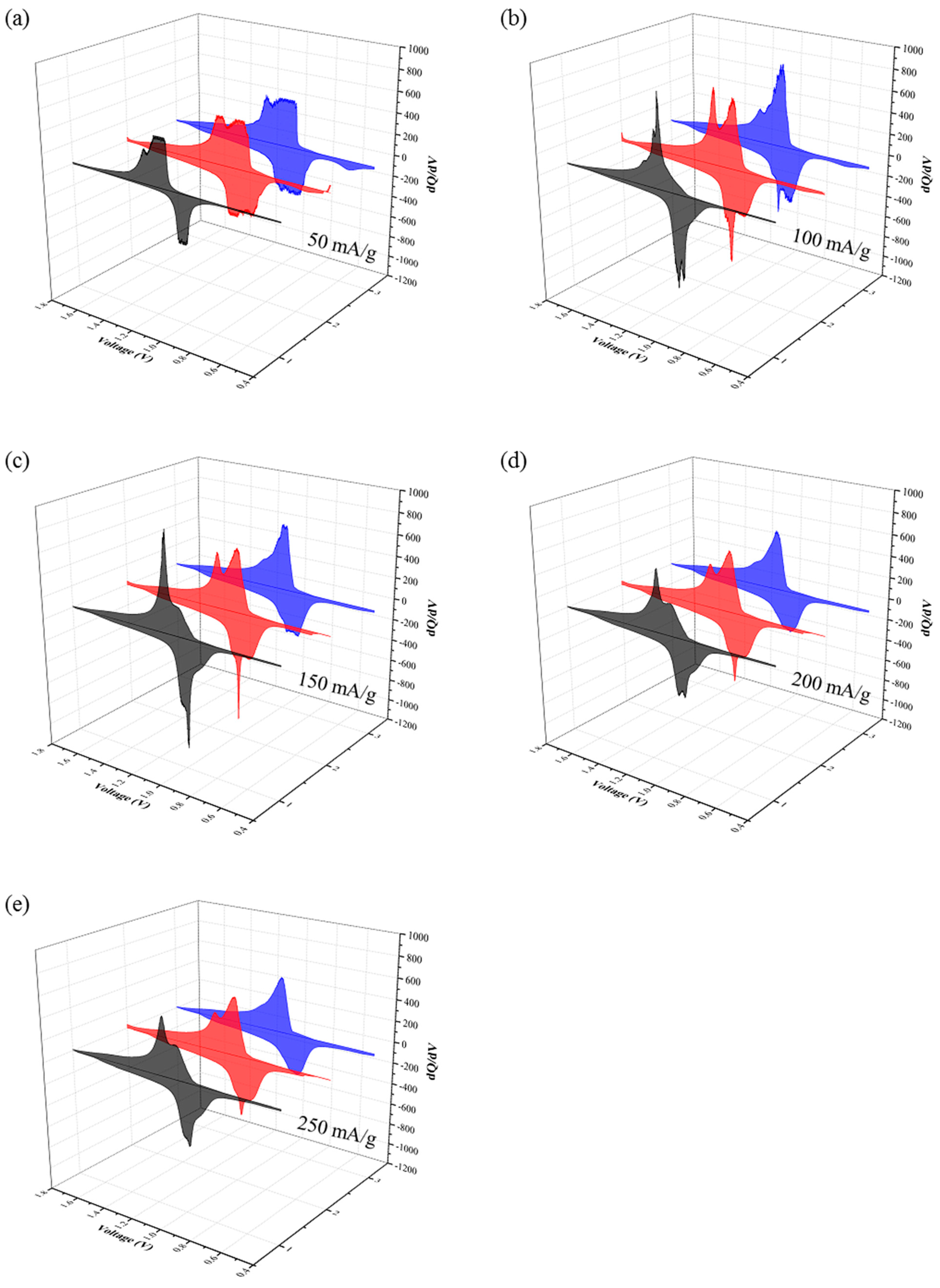
3.2. Electrochemical Performance of BCS-VONF

The produced BCS-VONF grown on carbon cloth was utilized as the cathode material for AZBs. In general, the addition of polymeric binders on electrodes not only aids in the attachment of the active material to the current collector, but also prevents the dissolution of active material on the electrolyte. However, the addition of binders proved to have several disadvantages, namely the increase in the weight of the electrode as well as the use of toxic solvents such as N-Methyl-2-Pyrrolidone (NMP). In addition, further costs had to be met for electrode preparation and processing materials. However, in this study a binder was not used on the working electrode. Thus, since V2O5 is known to be soluble in water viz. 8 g/L at 20 °C, high Zn salt content (3.0 M) was utilized to minimize the dissolution of V2O5 in water and to improve its electrochemical performance [23].
Consequently, different Zn salts, Zn(OTf)2, ZnSO4, and ZnCl2, were investigated and used to prepare the 3.0 M Zn salt electrolytes. As shown in Figure S4, to verify the reactivity and dissolution, the BCS-VONF were placed in the different Zn salt electrolytes. Thus, the ratio between the amount of BCS-VONF used per mL of the 3.0 M Zn salt electrolyte was found to be similar to the ratio between the active material and the electrolyte used for the prepared battery. It can be observed, therefore, that BCS-VONF can still be dissolved in 3.0 M ZnSO4 solution, as shown in Figure S4a(i). Chemical reaction occurred when the BCS-VONF were placed in the 3.0 M ZnCl2 leading to the white powder precipitate (Figure S4a(ii)). Further, BCS-VONF were only dispersed in the 3.0 M Zn(OTf)2 as in Figure S4a(iii) without noticeable dissolution and chemical reaction, as indicated by the clear solution and the unchanged physical appearance of the BCS-VONF, respectively. Hence, both the 3.0 M ZnSO4 electrolyte and 3.0 M Zn(OTf)2 electrolyte were used to investigate the electrochemical performance of BCS-VONF.
In Figure 4a, the galvanostatic charge–discharge test of BCS-VONF for both the 3.0 M ZnSO4 electrolyte and 3.0 M Zn(OTf)2 electrolyte is shown. It can be observed that the capacity of BCS-VONF under the 3.0 M ZnSO4 electrolyte increased rapidly; the highest discharge capacity being 211.36 mAh g−1. However, after ~20 cycles, the capacity suddenly dropped and the battery failed. This phenomenon can be attributed to the dissolution of BCS-VONF in the 3.0 M ZnSO4 electrolyte. As shown in Figure S4a(i), this agreed well with the dissolution of BCS-VONF in the 3.0 M ZnSO4 electrolyte. In contrast, Figure S4b(i) shows that even after 2 months storage, relatively less BCS-VONF can be observed; signifying that BCS-VONF was further dissolved in the 3.0 M ZnSO4 solution. Nevertheless, the capacity of BCS-VONF under 3.0 M Zn(OTf)2 electrolyte increased until ~30th cycle, and thereby reached a maximum discharge capacity of 155 mAh g−1 before the capacity stabilized. This demonstrated that the BCS-VONF proved to be stable in the 3.0 M Zn(OTf)2 electrolyte, even in the absence of binder. This phenomenon agreed well with the observation in Figure S4a(iii), where no noticeable change in the physical appearance of BCS-VONF was observed, even after 2 months storage (Figure S4b(ii)). The BCS-VONF were well dispersed and did not precipitate even after 2 months storage.
As shown in Figure 4b, the electrochemical performance of BCS-VONF under the 3.0 M Zn(OTf)2 electrolyte was further analyzed by performing the rate capability test with three repetitions. It was observed that the capacity of the BCS-VONF continuously increased until the 30th cycle, even if the current density increased (50 mA g−1, 100 mA g−1, and 150 mA g−1) every 10 cycles. After the 30th cycle, when the current density further increased to 200 mA g−1, the discharge capacity slightly dropped. However, it can still be observed that after 10 cycles at 200 mA g−1, the discharge capacity slightly increased (40th cycle). A further increase in the current density to 250 mA g−1 showed a slight decrease in discharge capacity to 110 mAh g−1. Due to the continuous increase in the capacity of BCS-VONF, regardless of the increase in the current density, the first set of rate capability test appeared erroneous. However, the second and third set of the rate capability test seemed more stable and hence was used for the analysis. Thus, it is evident that from the second to the third repetition of the rate capability test, at different applied current densities, the % capacity retentions, as seen in Table S1, were found to be greater than 90%, indicating a stable cathode material even after varying the applied current densities (increase and decrease) three times. After the third repetition, when the current density was rapidly decreased to 50 mA g−1 (the fourth repetition), the average discharge capacity slightly dropped to 157 mA g-1, but the % capacity retention was still ~97.5% indicating a very stable cathode material. In comparison to other studies that utilize V2O5 as a cathode material, the obtained capacity falls short in a specific capacity [7,23,31,39]. However, in calculating the capacity of the battery, the active material is not the only weight being considered. All the other components of the battery were added. For simplicity, if the weight of the whole electrode is considered (not only the active material), the capacity will be ~70% of the declared value, i.e., capacity per total weight of the electrode (the weight of current collector is not included). After considering the total weight of the electrode, the obtained discharge capacity of BCS-VONF is comparable with the previous studies. Furthermore, the removal of an extra component, i.e., the binder, should decrease the production and materials cost and ease the electrode manufacture [32]. Other additives, such as CNT and rGO, which greatly improve the capacity and stability of the cathode material, is not the focus of this study.
In Figure S5, the charge–discharge profile of BCS-VONF indicates small charge–discharge capacity polarization, at different applied current densities; thus, denoting a stable cathode. Plateaus were also observed at ~1 and ~1.2 V for the discharge and charge profiles respectively, before voltage suddenly dropped (discharge)/went up (charge). This phenomenon signified good performance of the battery with BCS-VONF under the 3.0 M Zn(OTf)2 electrolyte, in addition to high capacity retention, even after three repetitions of the rate capability test.
To understand the phenomena that occurred during the rate capability test in Figure 4b, the dQ/dV plots, at different applied current densities for the different sets (repetitions) of rate capability test, were analyzed, as shown in Figure 5 and Figure S6. In Figure 5, it was clear that for all the applied current densities, the initial dQ/dV curve (black) showed reduction/oxidation peaks at 1.01/1.14 and 0.98/1.03 V; where the former was more prominent than the latter. The observed reduction and oxidation peaks correspond to the intercalation and deintercalation of Zn2+ into the V2O5 matrix [8,39,40].
On the second repetition of the rate capability test, the dQ/dV curve (red) of all the applied current densities showed that the intensity of the reduction peak at 1.01 V decreased while the peak at 0.98 V intensified. In addition, a protruding reduction peak at 0.9 V was observed resulting in a total of three reduction peaks. Similar phenomenon can be witnessed for the oxidation peaks, where the intensity of the peak at 1.14 V decreased with an increase in the intensity of the peak at 1.03 V. On the third repetition of the rate capability test, a further decrease was observed in the intensity of reduction peaks at 1.01 and 0.98 V with a slight increase in the intensity at 0.9 V. Likewise, a further decrease in intensity at 1.14 V with a slight increase at 1.03 V oxidation peaks was observed.
The decrease and increase in the reduction and oxidation peaks, at different rate capability test repetitions, can be associated with the different reactions of Zn2+ to the different oxidation states of V. This is in agreement with other studies where the reduction and oxidation peaks vary depending on the compound/oxidation states of V. According to a previous study, V2O5 has three reduction peaks at 0.52, 0.93, and 0.98 V, with four oxidation peaks at 0.71, 0.95, 1.22, and 1.43 V. However, if V4+ was included in V2O5 the reduction/oxidation peaks shift to the right as follows: 0.61/0.74, 0.92/0.91, and 1.04/1.12 V [39]. As for H2V3O8 (V4.8+ oxidation state), the reduction/oxidation peaks were found to be 0.49/0.54 and 0.73/0.98 V [40]. Similarly, for V10O24•12H2O (V4.8+ oxidation state), the reduction/oxidation peaks were 0.97/1.04 V [41]. On the other hand, a further decrease in the oxidation state of V to 4+ resulted in a lower reduction/oxidation peak position. For VO2, the reduction/oxidation peaks were 0.9/1.04 and 0.52/0.78 V [40]. The continuous increase in capacity, even after the increase in the current density, might be due to the phase transformation which brings about the change in the oxidation state of V [27].

4. Conclusions

BCS-VONF on carbon cloth were obtained via a simple one-step hydrothermal process. The dissolution and reaction of the BCS-VONF in different electrolytes, namely 3.0 M Zn(OTf)2, 3.0 M ZnSO4, and 3.0 M ZnCl2, were examined. Thus, it was seen that BCS-VONF reacted with 3.0 M ZnCl2 to form a white precipitate while 3.0 M ZnSO4 could not prevent further dissolution of BCS-VONF. However, when placed in 3.0 M Zn(OTf)2, no noticeable change in the physical appearance of BCS-VONF was observed; the BCS-VONF were well dispersed in the solution and did not precipitate even after 2 months of storage. Consequently, the electrochemical performance of the BCS-VONF, as a cathode material for AZBs, agreed well with the results obtained from the reaction and dissolution of the different electrolytes. When the 3.0 M ZnSO4 electrolyte was used, capacity rapidly increased, but after ~20 cycles, it suddenly dropped leading to battery failure. This can be attributed to the dissolution of V2O5 in the 3.0 M ZnSO4 electrolyte. On the other hand, when the 3.0 M Zn(OTf)2 electrolyte was used, stable electrochemical performance was observed, as indicated by the stable galvanostatic charge–discharge cycles. With regards to the 3.0 M Zn(OTf)2 electrolyte, the rate capability test of BCS-VONF showed a promising result with excellent capacity retention. Thus, this demonstrated that BCS-VONF proved to be very stable in AZBs (3.0 M Zn(OTf)2) even in the absence of a polymeric binder.

Supplementary Materials

The following are available online at https://www.mdpi.com/1996-1073/13/1/31/s1: Figure S1: (a) BCS-VONF on a 150 mm Ø Whatman filter paper No. 1, (b) BCS-VONF dispersed in water to separate the individual fibers, and (c) the V2O5 powder used for hydrothermal process to produce the BCS-VONF. Figure S2: Energy dispersive spectroscopy (EDS) analysis (top) of BCS-VONF and the corresponding atomic percentages of V and O (bottom). Figure S3: Wulff constructed equilibrium shape of V2O5 crystal (left), indicating the areas occupied by the three low-index surfaces. Table of the surface energies of the three low-index surfaces. Figure S4: (a) BCS-VONF placed in (i) 3.0 M ZnSO4, (ii) 3.0 M ZnCl2, and (iii) 3.0 M Zn(OTf)2, (b) BCS-VONF dispersed for 2 months in (i) 3.0 M ZnSO4 and (ii) 3.0 M Zn(OTf)2. The used ratio of BCS-VONF to electrolyte for all samples was similar to the ratio of the active material to the electrolyte used in the electrochemical test. Table S1: Percentage capacity retention from the second to the third repetition of the rate capability test for various applied current densities. Figure S5: Charge–discharge profile of BCS-VONF at different current densities. Figure S6: dQ/dV vs. V graph of BCS-VONF at different repetitions: first (a), second (b), and third (c) of rate capability test. The black, red, blue, magenta, and olive colors correspond to the different applied current densities i.e., 50, 100, 150, 200, and 250 mA g−1, respectively.

Author Contributions

Conceptualization, L.M.D.J.-C. and S.K.; methodology, L.M.D.J.-C., R.D.C., and S.K.; investigation, L.M.D.J.-C. and R.D.C.; formal analysis, L.M.D.J.-C.; writing—original draft preparation, L.M.D.J.-C.; writing—review and editing, A.S., M.T.N., T.Y., J.M., and S.K.; supervision, S.K.; funding acquisition, S.K.; project administration, S.K. All authors have read and agreed to the published version of the manuscript.

Funding

This research was funded by the Energy Storage Cluster of Chulalongkorn University and National Science and Technology Development.

Acknowledgments

L.M.D.J.-C. and R.D.C. would like to thank the Postdoctoral Fellowship of Chulalongkorn University via Ratchadapisek Somphot Fund. S.K. thanks Hokkaido University for financial support for his stay in Sapporo.

Conflicts of Interest

The authors declare no potential conflict of interest.

Abbreviations

AZBAqueous zinc-ion battery
BCS-VONFBinder-free centimeter long single-crystal V2O5 nanofibers
EESElectrical energy storage
LIBLithium-ion battery
SHEStandard hydrogen potential
ZIBZinc-ion battery
PVDFPoly(vinylidene fluoride)
PTFEPoly(tetrafluoroethylene)
CMCCarboxymethyl cellulose
NMPN-methyl-2-pyrrolidone
DIDeionized
SEMScanning electron microscope
TEMTransmission electron microscope
XRDX-ray diffraction
XPSX-ray photoelectron spectroscopy
EDSEnergy dispersive spectroscopy
SAEDSelected area electron diffraction

References

  1. Zhang, S. Status, Opportunities, and Challenges of Electrochemical Energy Storage. Front. Energy Res. 2013, 1. [Google Scholar] [CrossRef] [Green Version]
  2. Larcher, D.; Tarascon, J.M. Towards greener and more sustainable batteries for electrical energy storage. Nat. Chem 2014, 7, 19. [Google Scholar] [CrossRef] [PubMed]
  3. Lao-Atiman, W.; Bumroongsil, K.; Arpornwichanop, A.; Bumroongsakulsawat, P.; Olaru, S.; Kheawhom, S. Model-Based Analysis of an Integrated Zinc-Air Flow Battery/Zinc Electrolyzer System. Front. Energy Res. 2019, 7. [Google Scholar] [CrossRef] [Green Version]
  4. Wu, X.; Song, K.; Zhang, X.; Hu, N.; Li, L.; Li, W.; Zhang, L.; Zhang, H. Safety Issues in Lithium Ion Batteries: Materials and Cell Design. Front. Energy Res. 2019, 7. [Google Scholar] [CrossRef] [Green Version]
  5. Ouyang, D.; Chen, M.; Huang, Q.; Weng, J.; Wang, Z.; Wang, J. A Review on the Thermal Hazards of the Lithium-Ion Battery and the Corresponding Countermeasures. Appl. Sci. 2019, 9, 2483. [Google Scholar] [CrossRef] [Green Version]
  6. Ould Ely, T.; Kamzabek, D.; Chakraborty, D. Batteries Safety: Recent Progress and Current Challenges. Front. Energy Res. 2019, 7. [Google Scholar] [CrossRef]
  7. Zhang, N.; Dong, Y.; Jia, M.; Bian, X.; Wang, Y.; Qiu, M.; Xu, J.; Liu, Y.; Jiao, L.; Cheng, F. Rechargeable Aqueous Zn–V2O5 Battery with High Energy Density and Long Cycle Life. ACS Energy Lett. 2018, 3, 1366–1372. [Google Scholar] [CrossRef]
  8. Ding, J.; Du, Z.; Gu, L.; Li, B.; Wang, L.; Wang, S.; Gong, Y.; Yang, S. Ultrafast Zn2+ Intercalation and Deintercalation in Vanadium Dioxide. Adv. Mater. 2018, 30, 1800762. [Google Scholar] [CrossRef]
  9. Tang, B.; Shan, L.; Liang, S.; Zhou, J. Issues and opportunities facing aqueous zinc-ion batteries. Energy Environ. Sci. 2019. [Google Scholar] [CrossRef]
  10. Xia, C.; Guo, J.; Lei, Y.; Liang, H.; Zhao, C.; Alshareef, H.N. Rechargeable Aqueous Zinc-Ion Battery Based on Porous Framework Zinc Pyrovanadate Intercalation Cathode. Adv. Mater. 2018, 30. [Google Scholar] [CrossRef]
  11. Konarov, A.; Voronina, N.; Jo, J.H.; Bakenov, Z.; Sun, Y.-K.; Myung, S.-T. Present and Future Perspective on Electrode Materials for Rechargeable Zinc-Ion Batteries. ACS Energy Lett. 2018, 3, 2620–2640. [Google Scholar] [CrossRef]
  12. Song, M.; Tan, H.; Chao, D.; Fan, H.J. Recent Advances in Zn-Ion Batteries. Adv. Funct. Mater. 2018, 28. [Google Scholar] [CrossRef]
  13. Li, H.; Ma, L.; Han, C.; Wang, Z.; Liu, Z.; Tang, Z.; Zhi, C. Advanced rechargeable zinc-based batteries: Recent progress and future perspectives. Nano Energy 2019, 62, 550–587. [Google Scholar] [CrossRef]
  14. Kao-ian, W.; Pornprasertsuk, R.; Thamyongkit, P.; Maiyalagan, T.; Kheawhom, S. Rechargeable Zinc-Ion Battery Based on Choline Chloride-Urea Deep Eutectic Solvent. J. Electrochem. Soc. 2019, 166, A1063–A1069. [Google Scholar] [CrossRef]
  15. Yang, D.; Tan, H.; Rui, X.; Yu, Y. Electrode Materials for Rechargeable Zinc-Ion and Zinc-Air Batteries: Current Status and Future Perspectives. Electrochem. Energy Rev. 2019, 2, 395–427. [Google Scholar] [CrossRef]
  16. Hosseini, S.; Han, S.J.; Arponwichanop, A.; Yonezawa, T.; Kheawhom, S. Ethanol as an electrolyte additive for alkaline zinc-air flow batteries. Sci. Rep. 2018, 8, 11273. [Google Scholar] [CrossRef] [Green Version]
  17. Hosseini, S.; Lao-atiman, W.; Han, S.J.; Arpornwichanop, A.; Yonezawa, T.; Kheawhom, S. Discharge Performance of Zinc-Air Flow Batteries Under the Effects of Sodium Dodecyl Sulfate and Pluronic F-127. Sci. Rep. 2018, 8, 14909. [Google Scholar] [CrossRef] [Green Version]
  18. Wang, B.; Han, Y.; Wang, X.; Bahlawane, N.; Pan, H.; Yan, M.; Jiang, Y. Prussian Blue Analogs for Rechargeable Batteries. iScience 2018, 3, 110–133. [Google Scholar] [CrossRef] [Green Version]
  19. Zhang, L.; Chen, L.; Zhou, X.; Liu, Z. Towards High-Voltage Aqueous Metal-Ion Batteries Beyond 1.5 V: The Zinc/Zinc Hexacyanoferrate System. Adv. Energy Mater. 2015, 5, 1400930. [Google Scholar] [CrossRef]
  20. Zhang, L.; Chen, L.; Zhou, X.; Liu, Z. Morphology-Dependent Electrochemical Performance of Zinc Hexacyanoferrate Cathode for Zinc-Ion Battery. Sci. Rep. 2015, 5, 18263. [Google Scholar] [CrossRef]
  21. Khamsanga, S.; Pornprasertsuk, R.; Yonezawa, T.; Mohamad, A.A.; Kheawhom, S. δ-MnO2 nanoflower/graphite cathode for rechargeable aqueous zinc ion batteries. Sci. Rep. 2019, 9, 8441. [Google Scholar] [CrossRef] [PubMed] [Green Version]
  22. Tang, B.; Zhou, J.; Fang, G.; Guo, S.; Guo, X.; Shan, L.; Tang, Y.; Liang, S. Structural Modification of V2O5 as High-Performance Aqueous Zinc-Ion Battery Cathode. J. Electrochem. Soc. 2019, 166, A480–A486. [Google Scholar] [CrossRef]
  23. Zhou, J.; Shan, L.; Wu, Z.; Guo, X.; Fang, G.; Liang, S. Investigation of V2O5 as a low-cost rechargeable aqueous zinc ion battery cathode. Chem. Commun. 2018, 54, 4457–4460. [Google Scholar] [CrossRef] [PubMed]
  24. Wang, L.; Huang, K.-W.; Chen, J.; Zheng, J. Ultralong cycle stability of aqueous zinc-ion batteries with zinc vanadium oxide cathodes. Sci. Adv. 2019, 5, eaax4279. [Google Scholar] [CrossRef]
  25. Zhang, N.; Cheng, F.; Liu, J.; Wang, L.; Long, X.; Liu, X.; Li, F.; Chen, J. Rechargeable aqueous zinc-manganese dioxide batteries with high energy and power densities. Nat. Commun. 2017, 8, 405. [Google Scholar] [CrossRef] [Green Version]
  26. Kundu, D.; Hosseini Vajargah, S.; Wan, L.; Adams, B.; Prendergast, D.; Nazar, L.F. Aqueous vs. nonaqueous Zn-ion batteries: Consequences of the desolvation penalty at the interface. Energy Environ. Sci. 2018, 11, 881–892. [Google Scholar] [CrossRef]
  27. De Juan-Corpuz, L.M.Z.; Nguyen, M.T.; Corpuz, R.D.; Yonezawa, T.; Rosero-Navarro, N.C.; Tadanaga, K.; Tokunaga, T.; Kheawhom, S. Porous ZnV2O4 Nanowire for Stable and High-Rate Lithium-Ion Battery Anodes. ACS Appl. Nano Mater. 2019, 2, 4247–4256. [Google Scholar] [CrossRef]
  28. Maggay, I.V.B.; De Juan, L.M.Z.; Lu, J.-S.; Nguyen, M.T.; Yonezawa, T.; Chan, T.-S.; Liu, W.-R. Electrochemical properties of novel FeV2O4 as an anode for Na-ion batteries. Sci. Rep. 2018, 8, 8839. [Google Scholar] [CrossRef]
  29. Maggay, I.V.B.; De Juan, L.M.Z.; Nguyen, M.T.; Yonezawa, T.; Chang, B.K.; Chan, T.S.; Liu, W.-R. ZnV2O4: A potential anode material for sodium-ion batteries. J. Taiwan Inst. Chem. Eng. 2018, 88, 161–168. [Google Scholar] [CrossRef]
  30. Qin, H.; Yang, Z.; Chen, L.; Chen, X.; Wang, L. A high-rate aqueous rechargeable zinc ion battery based on the VS4@rGO nanocomposite. J. Mater. Chem. A 2018, 6, 23757–23765. [Google Scholar] [CrossRef]
  31. Yin, B.; Zhang, S.; Ke, K.; Xiong, T.; Wang, Y.; Lim, B.K.D.; Lee, W.S.V.; Wang, Z.; Xue, J. Binder-free V2O5/CNT paper electrode for high rate performance zinc ion battery. Nanoscale 2019, 11, 19723–19728. [Google Scholar] [CrossRef] [PubMed]
  32. Huang, Y.; Liu, J.; Huang, Q.; Zheng, Z.; Hiralal, P.; Zheng, F.; Ozgit, D.; Su, S.; Chen, S.; Tan, P.-H.; et al. Flexible high energy density zinc-ion batteries enabled by binder-free MnO2/reduced graphene oxide electrode. Npj Flex. Electron. 2018, 2, 21. [Google Scholar] [CrossRef] [Green Version]
  33. Corpuz, R.D.; De Juan, L.M.Z.; Praserthdam, S.; Pornprasertsuk, R.; Yonezawa, T.; Nguyen, M.T.; Kheawhom, S. Annealing induced a well-ordered single crystal δ-MnO2 and its electrochemical performance in zinc-ion battery. Sci. Rep. 2019, 9, 15107. [Google Scholar] [CrossRef] [PubMed] [Green Version]
  34. Jiao, T.; Yang, Q.; Wu, S.; Wang, Z.; Chen, D.; Shen, D.; Liu, B.; Cheng, J.; Li, H.; Ma, L.; et al. Binder-free hierarchical VS2 electrodes for high-performance aqueous Zn ion batteries towards commercial level mass loading. J. Mater. Chem. A 2019, 7, 16330–16338. [Google Scholar] [CrossRef]
  35. Goclon, J.; Grybos, R.; Witko, M.; Hafner, J. Relative stability of low-index V2O5surfaces: A density functional investigation. J. Phys. Condens. Matter 2009, 21, 095008. [Google Scholar] [CrossRef] [PubMed]
  36. Liu, F.; Song, S.; Xue, D.; Zhang, H. Selective crystallization with preferred lithium-ion storage capability of inorganic materials. Nanoscale Res. Lett. 2012, 7, 149. [Google Scholar] [CrossRef] [PubMed] [Green Version]
  37. Zimmermann, R.; Claessen, R.; Reinert, F.; Steiner, P.; Hüfner, S. Strong hybridization in vanadium oxides: Evidence from photoemission and absorption spectroscopy. J. Phys. Condens. Matter 1998, 10, 5697–5716. [Google Scholar] [CrossRef]
  38. Silversmit, G.; Depla, D.; Poelman, H.; Marin, G.B.; De Gryse, R. Determination of the V2p XPS binding energies for different vanadium oxidation states (V5+ to V0+). J. Electron. Spectrosc. Relat. Phenom. 2004, 135, 167–175. [Google Scholar] [CrossRef]
  39. Hu, P.; Yan, M.; Zhu, T.; Wang, X.; Wei, X.; Li, J.; Zhou, L.; Li, Z.; Chen, L.; Mai, L. Zn/V2O5 Aqueous Hybrid-Ion Battery with High Voltage Platform and Long Cycle Life. Acs Appl. Mater. Interfaces 2017, 9, 42717–42722. [Google Scholar] [CrossRef]
  40. He, P.; Quan, Y.; Xu, X.; Yan, M.; Yang, W.; An, Q.; He, L.; Mai, L. High-Performance Aqueous Zinc–Ion Battery Based on Layered H2V3O8 Nanowire Cathode. Small 2017, 13, 1702551. [Google Scholar] [CrossRef]
  41. Wei, T.; Li, Q.; Yang, G.; Wang, C. High-rate and durable aqueous zinc ion battery using dendritic V10O24·12H2O cathode material with large interlamellar spacing. Electrochim. Acta 2018, 287, 60–67. [Google Scholar] [CrossRef]
Figure 1. (a) SEM image of the produced particles on carbon cloth with pictures inset of the bare (black) and fiber coated (yellow) carbon cloth, (b) Magnified SEM image of (a), and (c) selected area electron diffraction (SAED) pattern of the fiber inset with the TEM image of the part where the SAED pattern was taken.
Energies 13 00031 g001
Figure 2. (a) XRD spectrum of the produced nanofibers and the corresponding XRD pattern of V2O5 with ICDD 72-0598 (b) Schematic diagram of V2O5 structure.
Energies 13 00031 g002
Figure 3. X-ray photoelectron spectroscopy (XPS) spectra of the produced nanofibers: (a) wide scan and narrow scans of (b) V 2p, (c) C 2s, and (d) O 1s.
Energies 13 00031 g003
Scheme 1. Formation of binder-free, centimeter long, single-crystal, V2O5 nanofibers (BCS-VONF) on carbon cloth.
Energies 13 00031 sch001
Figure 4. (a) Gravimetric charge–discharge test of BCS-VONF at 100 mA g−1 current density using 3.0 M Zn(OTf)2 (black) and 3.0 M ZnSO4 (red). The black and red square markers refer to the coulombic efficiencies using 3.0 M Zn(OTf)2 and 3.0 M ZnSO4, respectively. The hollow and filled circles correspond to charge and discharge capacities, respectively. (b) Rate capability of BCS-VONF with voltage window of 0.4–1.8 V.
Energies 13 00031 g004
Figure 5. dQ/dV vs. V plots of BCS-VONF at different applied current densities: (a) 50 mA g−1, (b) 100 mA g−1, (c) 150 mA g−1, (d) 200 mA g−1, and (e) 250 mA g−1. The first (black), second (red), and third (blue) correspond to the repetition of the applied current density on the rate capability test, as in Figure 4.
Energies 13 00031 g005

