1. Introduction
Non-orthogonal multiple access (NOMA) has been identified as an upcoming physical layer communication scheme and is visualized to be an essential part of 5G wireless communication systems. The benefit of NOMA is to serve multiple users at the same time/frequency/code, but with different power levels, which yields a significant spectral efficiency gain over conventional orthogonal multiple access [
1].
In NOMA, the user that has the highest effective channel gain will be treated as the highest priority in the sequence, while the user with the least channel gain will be positioned last in the queue. The remaining users will be placed in the queue in accordance with their degree of effective channel gain. One of the biggest benefits of NOMA is that it helps users that have a weak signal by allocating a higher fraction of power to it [
2]. In conventional systems that are based on orthogonal multiple access (OMA) schemes, users are unable to access a given frame once it has been allocated to a certain user. This has a negative impact upon the total system throughput. However, when NOMA is employed, users that have a strong signal are able to transmit data via a slot that has already been allocated to a user that has a weaker signal [
3]. Assigning the users to slots in this way will not have a negative impact on the performance of the weaker user that has already experienced the effect of channel fading. Furthermore, the user that has a stronger signal will avoid any interference caused by the poor signal due to the application of a successive interference cancellation (SIC) operation [
4]. As such, the efficient allocation of resources in this manner will enhance the overall data rate of the system. The contributions of this study can be summarized as the following:
End-to-end SINR and outage probability for near and far users in the downlink NOMA system are mathematically derived with the outage probability for each user.
Energy consumption of the downlink NOMA system is derived for near and far users under a specific SINR threshold.
Optimization of power splitting ratio and power allocation coefficients by using the Genetic Algorithm (GA) to maximize the energy efficiency under eligible SE.
The remainder of the paper is organized as follows.
Section 2 discusses recent developments and a critical review of the previous studies, while the data rate for cooperative NOMA is presented in
Section 3.
Section 4 describes the proposed system model. In
Section 5, the optimization of EE cooperative NOMA energy harvesting is illustrated. Finally, conclusions are presented in
Section 6.
2. Related Works
One problem associated with the exponential growth in smart devices is that the spectrum resource that is currently available in practical systems is relatively limited. As such, next-generation wireless communication systems need to be enhanced so that they can adequately manage vast quantities of data traffic [
5,
6]. This will only be possible by delivering high spectral efficiency within a limited spectrum.
As a result of the increasing demand for the Internet of Things (IoT) and the associated QoS requirements, novel multiple-access technologies need to have the capacity to support the connectivity between massive numbers of users and devices. According to [
7], which was published by Qualcomm Technologies Inc., in addition to the prerequisites described above, 5G networks will also need to provide deep and universal coverage. This entails that the novel multiple-access technologies will need to reach remote locations. There is also a need to ensure that both weak and strong users of the 5G networks have equitable access [
8].
As such, NOMA is a multiple access technique that can potentially address the challenge of meeting the needs of 5G mobile networks. This is reflected by the fact that a variety of technology companies, including Huawei, are currently implementing NOMA as a standard of 5G.
A great deal of attention has been paid in recent times by cooperative systems to NOMA [
9,
10]. The authors of [
11] put forward a cooperative NOMA system by utilizing the knowledge that users with superior channel conditions will receive prior information regarding the communications of others. This allows those with strong connections to retransmit messages sent by those with weak connections. The concept of NOMA is now employed to boost the spectral efficiency for cooperative relaying systems.
The principle of power-domain NOMA employs the superposition coding (SC) for transmission and SIC for the reception; this permits many users to undertake the simultaneous transmission of information through the same subcarrier channel. The method of setting the SIC decoding order is dependent on wireless link channel characteristics related to each pair of transmitters and receivers, i.e., the main concept is for the information received by users with the strongest wireless links to be susceptible to decoding without interference. The authors of [
12] proposed a basic scheme of power-domain NOMA, along with a discussion of potential ways in which the problems encountered when using this technique could be mitigated. The authors of [
13] also looked at power-domain NOMA and downlink operations, assuming SIC at the receiver and SC at the transmitter. In Ref. [
14], the authors looked at power and channel allocation of downlink cellular systems. Authors in Ref. [
15] proposed the idea of power division multiple access (PDMA), proposing an orthogonal PDMA protocol based on the bit-orthogonality principal. Additionally, they examined the energy efficiency of their suggested technique when employing standard time-frequency division multiple access techniques. The majority of the works mentioned above undertake analysis of throughput for the characterization and comparison of the different techniques’ performance. It must be noted that when power resources are limited, the available energy must be efficiently utilized for every new information to be transmitted.
Thus a number of researchers have chosen energy efficiency as a key driver for the design of wireless networks, in which the best ways of allocating resources must be paramount [
16].
On the other hand, the use of radio-frequency (RF) signals for the Simultaneous Wireless Information and Power Transfer (SWIPT) has become a valuable source of energy harvesting (EH) because it is able to simultaneously carry both energy and information [
17]. Another alternative power source from the wireless transmission that can be exploited by the use of near-field wireless power transfer (WPT) is presented in [
18]. EH brings more improvement in energy efficiency compared to conventional cooperative relaying by decreasing the energy consumption. On the other hand, the use of SWIPT may reduce spectral efficiency (SE) [
19] because the maximization of the total data rate will achieve higher SE for the next wireless generation.
3. Data Rate of Users in Cooperative NOMA System
According to
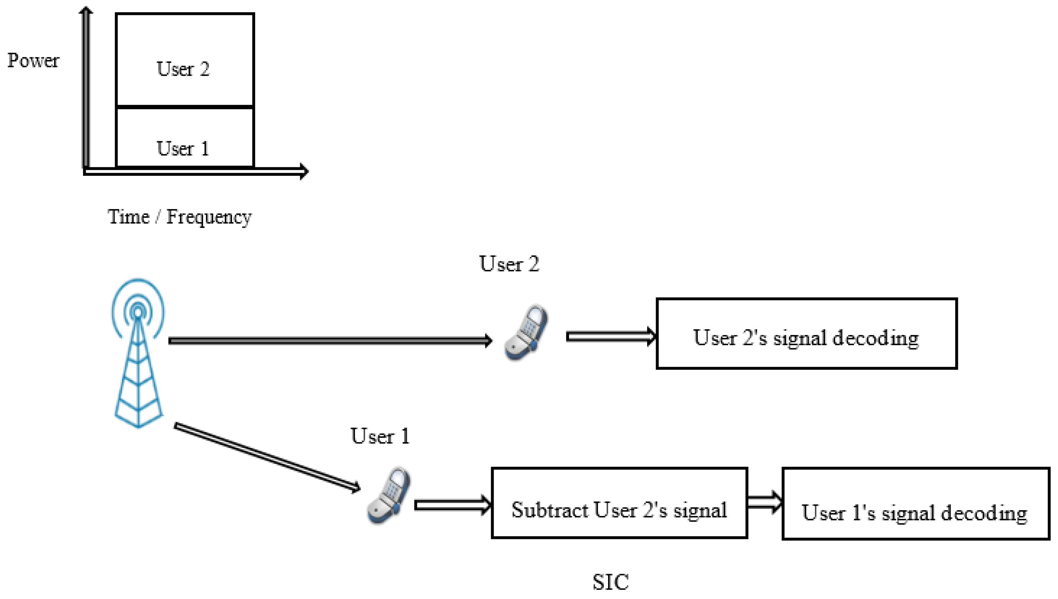
Figure 1, the BS firstly broadcasted the transmitted signal for both users, where User 2 has worse channel gain compared to User 1. The users with worse and better channel condition are usually known as weak user and strong user, respectively. As shown in the figure, User 1 firstly subtracts the User 2 signal through SIC, before it decodes its signal. On the other hand, User 2 considers the User 1 signal as noise, and its signal is directly decoded.
To illustrate the difference between OMA and NOMA, a unity system transmission bandwidth for NOMA is assumed. In downlink NOMA, the optimal order for decoding is the order of increasing channel gain normalized by noise and inter-cell interference power,
which is called the channel gain. Based on this order, we assume that any user can correctly decode the signals of other users whose decoding order comes before the corresponding user. Thus,
UEi can remove the inter-user interference from the
jth user whose
is lower than
. In a two-users case, assuming that
, User 2 does not perform interference cancellation because it comes first in the decoding order. The throughput of
Ui, i.e.
Ri can be represented as:
From the above equations, it can be seen that the power allocation for each User 1 and User 2 dramatically affects the user throughput performance and consequently, the modulation and coding scheme (MCS) used for the data transmission of each user is also affected. By adjusting the power allocation ratio,
P1/
P2, the BS can flexibly control the throughput of each user. The overall cell throughput, cell-edge throughput and user fairness are closely related to the power-allocation scheme adopted. For OMA, the bandwidth of
(0 <
< 1) Hz is assigned to User 1 and the remaining bandwidth,
Hz, is assigned to User 2. The throughput of user
Ui,
Ri, is represented as:
In NOMA, the performance gain compared to OMA increases when the difference in channel gains and the path loss between users is large. For example, in
Figure 2, a case of two users with a cell-interior user and a cell-edge user is assumed, where
and
are set to 20 and 0 dB, respectively. For OMA with equal bandwidth and equal transmission power allocated to each user (
= 0.5,
P1 =
P2 = 0.5
P), the user rates are calculated according to (3) and (4) as
R1 = 3.33 bps and
R2 = 0.50 bps, respectively. On the other hand, in NOMA, when the power allocation is conducted as
P1 = 1/5
P and
P2 = 4/5
P, the user rates are calculated according to (1) and (2) as
R1 = 4.39 bps and
R2 = 0.74 bps, respectively. The corresponding gains of NOMA over OMA are 32% and 48% for User 1 and User 2, respectively. As shown, NOMA provides a higher sum rate than OMA.
Figure 3 shows the data rates for User 1 and 2 in OMA and NOMA networks, based on the Equations (1)–(4), defined previously. As shown, it is clear that the NOMA outperforms OMA systems. This is because in OMA systems, the upper bound on
Ri is using all the power to communicate to user
i without any data rate for the other users. As shown, the data rate for User 1 is greater than the data rate of User 2, because User 1 is considered as the strong user (near to BS), so the data rate is also expected to be more than User 2.
Cooperative NOMA fully utilizes the information obtainable within the earlier OMA system. Authors in Ref. [
20] illustrated that better performance is achieved with a cooperative NOMA scheme compared to non-cooperative schemes when the link between source and relay is experiencing a slow-fading channel. In [
21], it was assumed that there is cooperation between BSs to perform the downlink transmission. Moreover, the authors investigated the system interference between cell-edge users. Meanwhile, Ref. [
22] attempts to improve the capacity of the system when employing a combination of dirty paper coding and cooperative NOMA for the optimization problem of resource scheduling.
Researchers have illustrated that implementing the relays within wireless networks has a great effect on reducing the fading and shadowing effect on the transmitted signal. Authors in [
23] proposed the cooperative NOMA scheme. The idea for this scheme is that users with good channel conditions act as EH relay nodes using SWIPT to support for users with weak channel conditions to strengthen the data transmission. The authors elaborated on the results through a successive detection policy at the side of the receiver, which illustrated that users with better channel conditions should decode messages for the other users. Prior studies done by [
24] concentrated on reducing pair-wise error probability (PEP). Authors in [
25] proposed a new policy to attain better performance for cooperative NOMA in terms of high coding gains. Authors in [
26] considered a Rayleigh fading channel to examine the obtainable average rate via a cooperative NOMA scheme. Ref. [
27] presented a new cooperative NOMA model for the purpose of SE improvement. Authors in Ref. [
28] placed the users in a random manner while examining the wireless transfer of the power within wireless NOMA networks. In this scheme, users close to the source act as an energy harvesting (EH) using the SWIPT relay to support users that are further away from the source.
The main concept for the transmission using cooperative NOMA is that the users with stronger signals and better channel conditions will act as relay nodes to aid the users that have weaker signals.
Figure 4 below illustrates the cooperative NOMA network.
The transmission using cooperative NOMA is divided into two major stages: direct transmission and cooperative transmission. In the direct transmission phase, a broadcast message is broadcasted for both the user with weaker channel conditions (User 2) and the user with stronger channel conditions (User 1).
Throughout the phase of cooperative transmission, after performing the SIC on User 1’s side in order to decode the message of User 2, User 1 will work as a relay node that retransmits information to User 2. Consequently, User 2 receives two different copies of the message via diverse channels. To summarize, transmission with cooperative NOMA has the benefit of decoding the message to the user with weaker channel conditions than the users with stronger channel conditions. Consequently, it is normal to consider users with stronger channel conditions as relay nodes. This will in turn improve the reliability of reception for users with weaker channel conditions.
4. System Model
In this section, a downlink cooperative NOMA is considered, which consists of a BS and
N near users and
M far users. One of the near users called
n is located at distance
d1 while one of the far users called
m is located at distance
d3. The distance between user
n and user
m is denoted by
d2. The BS communicates with near and far users using the NOMA scheme. The near user employs an energy harvesting technique to amplify and forward the signal to the far user assuming a power splitting ratio method. The power allocation coefficient is applied at the BS, where the
coefficient is provisioned to user n and the
coefficient is provisioned to user
m.
is the path loss exponent. The proposed system model is shown in
Figure 5.
Table 1 represents the system parameters used in the simulation.
represents the minimum combined SNR for near and far users.
represents the maximum energy source.
4.1. NOMA Mathematical Model
In the first time transmission phase, the received data from the BS with energy
to the near and far users can be written as:
The data is amplified with gain
G and forwarded from near user to far user, taking into account the power splitting ratio due to the EH technique. The following equations represent the model of amplifying, and forwarded the data that occurred at the near user at the input of the EH system:
where
is additive white Gaussian noise (AWGN) from the information receiver.
is the power splitting ratio. The signal at the output EH system can be written as:
where
is the energy of the near user. In the second time transmission phase, the received data from the near user to the far user can be written as:
Equation (9) can be written as:
From (6) the signal to interference and noise ratio (SINR) for the path from BS to the far user can be written as:
To find the SINR for the path from near user to far user, the end-to-end path should be computed as:
where:
The energy of the near user can be written as [
29]:
where
is the energy efficiency, which is equal to 0.6 in this work and
T is the block interval. The amplification gain,
G, can be written as [
30]:
After substitute (14) and (15) into (12) and after mathematical simplification, assuming
, the SINR from the near to far user can be written as:
where
represents the interference and can be written as:
4.2. Derivation of the Parameters of Near and Far Users
In this section, the SINR and the outage probability for the paths from BS to far user and from the near to the far user are derived over a specific condition. Finally, the total energy consumption is derived. In order to simplify the equations, we can consider:
Equation (12) can be written as:
where
.
Also, (11) can be written as:
After finding the SINR for near and far users, the outage probability should be derived for near and far users. The outage probability for the signal from the near user to far user is denoted by , where the outage probability for the signal to the far user is denoted by .
1. Probability of far user can be written as:
where
.
is the data rate for the far user.
For that,
can be written as:
where:
2. Probability of near user can be written as:
where:
,
,
,
.
.
is the data rate for the near user.
The rest of the derivation can be found in
Appendix A towards the last page of this paper. The last step is to find the total energy consumption
of the two paths. To find
, a threshold SINR
should be assumed, which is lesser or equal to the SINR of any paths.
We can write (31) as:
Equation (32) can be solved to find
, where
can be written as:
where
For that, the total energy consumption can be written as:
Finally, the main equation of EE can be written as:
4.3. Optimization of NOMA Cooperative Relaying
The main aim of the optimization technique is to find the best values of power allocation coefficients and power splitting ratio that gives the maximum EE under an accepted SE called
. Assuming the total system bandwidth
[
31], and without the loss of generality, we set
M =
N = 2. The minimum data rate can be written as
. To compute the maximum EE under accepted SE,
should be satisfied. The data rate for the near user is set to
and the data rate for the far user is set to
. The minimum SE requirement can be stated as:
Equation (37) can be written as:
From (38), we can find that constraint to achieve a minimum SE.
where:
The balance between SE and EE in the NOMA cooperative system can be achieved based on the previous Equation (36) can be expressed as a function of:
The problem formulation is described as follows:
It is clear that the problem posed by (42a) is a nonlinear optimization problem. A Genetic Algorithm (GA) technique has been adopted to maximize the EE under the constraints of satisfying a minimum SE. This algorithm has different advantages, such as lower computational costs, better performance, and provides suitable results compared to other complex methods. The simulation model has been implemented in MATLAB. The model applied is described in
Table 2.
5. Simulation and Numerical Results
This section illustrates the performance of NOMA networks for two users, one of the users is nearby the BS (known as ‘near user’ or User 1 used interchangeably in this paper) and the other user is far from the BS (‘far user’ or User 2). To illustrate the total SINR at the far user,
Figure 6 shows the total SNR with different values of
Es. As shown, by increasing the
Es, the total SNR is enhanced. This showed that at
Es = 1 J, the total SINR is about 0.4, which is greater than the SNR threshold of 0.31 (−5 dB).
Figure 7 illustrates the outage probability (OP) of the path from BS to User 1 via User 2. As shown, the slope of the OP for a near user differs from the slope of OP for the far user, due to the different OP equations of both users. The OP for a far user is a function of power allocation coefficients. The OP for a far user depends on the variable
M only, while in the case of a near user, the OP is a function of power allocation coefficients and power splitting ratio. The OP for a near user depends on the variables
M and
N at the same time. As shown in
Figure 7, the OP of the near user performs better compared to the far user. For example, to achieve an outage probability of
, the OP for the far user requires around 20 dB SINR, while in the case of a near user, it requires around 11 dB SINR. The OP results match with different recent research works such as [
32,
33].
The GA has been used to maximize EE while satisfying SE with different constraints: (i) the power allocation of the near user (
), (ii) the power allocation of the far user (
), (iii) the power splitting coefficient (
. The impact of these parameters on the EE is shown in
Figure 8. As shown, after 60 iterations, most of the constraints become constant at a specific value.
After maintaining the constraints, the optimized constraints are substituted in the EE equation.
Figure 9 illustrated the performance of EE at different constraints values. As shown, the optimized constraints of the EE become maximum i.e.,
EEmax and reach 0.5 Mbits/Joule.
Figure 10 illustrates the SE–EE metric for NOMA systems for different values of
Es. If the minimum SE becomes larger than a specific threshold
, the EE begins to decrease, because at high SE, the more transmitting power is needed to face the expanding in QoS requirements or by increasing the number of users with poor channel conditions. As shown in
Figure 11, at
Es = 3 J, the maximum EE occurred at 11 bits/sec/Hz with EE 0.425M bits/Joule, while at
Es = 1 J, the maximum EE occurred at 9 bits/sec/Hz with EE 0.325 M bits/Joule. The SE–EE results match with different recent research works, such as published in Ref. [
33,
34].
To compare OMA and NOMA, the authors in Ref. [
35] investigate the performance of the SE–EE metric under the OMA system. It can be seen that in the case of OMA, there is no internal interference within the same cell, where in the case of NOMA, the interference occurred between users in the same cell. Another point that should be noted, in the case of the OMA system, SE is obtained based on an adaptive transmission technique. While in the case of the NOMA system, a minimum accepted SE is obtained based on an objective function that depends on the power allocation coefficient. Finally, it can be seen that, in the case of OMA, the SE–EE shape almost follows a Gaussian shape because of the trade-off between SE and EE, while in case of NOMA, there is a flat linear region that starts at 1 Mbits/J until 3 Mbits/J. This proves that a NOMA network provides high SE and EE performance.
Figure 11 shows the compassion between cooperative OMA and cooperative NOMA. Based on the parameters in
Table 1, the OMA network provides a higher flat region compared to Ref. [
36], due to using actual distances and a different SNR threshold. It is clearly shown that the NOMA system provides high EE compared to the OMA system.
6. Concluding Remarks
The paper has summarized the NOMA system with the RF–EH technique, the system model which assumes a near user to the BS and a far user to the BS. Firstly, the SINR for each user has been presented. The SINR for the far user depends on the power allocation coefficients, while the SINR for the near user depends on the power allocation coefficients and the power splitting ratio, because the near user, which is defined as the strong user, forwards the signal to the far user after applying a power splitting process.
The outage probability performance for the near and the far users were also derived. The outage probability of the cooperative path, which is defined as the near user, was compared with the outage probability of the direct path, which is defined as the far user. The derivation of EE in a cooperative NOMA system was applied by optimizing the power allocation coefficients and power splitting ratio to achieve the maximum EE under . GA was used for optimization, where the performance of the constraints was shown. The results achieved from GA were the optimized power allocation coefficients and the power splitting ratio. Finally, the SE–EE metric has been illustrated for different energy sources, which indicates that NOMA systems can be used to achieve high EE at accepted SE.


