Article

Numerical and Experimental Study on the Heat Dissipation Performance of a Novel System

1
Department of Building Environment and Equipment, Hefei University of Technology, Hefei 230009, China
2
Department of Architecture and Civil Engineering, West Anhui University, Lu’an 237012, China
3
College of Civil Engineering and Architecture, Jiaxing University, Jiaxing 314001, China
4
Qinghai College of Architectural Technology, Xining 810002, China
5
School of Environment and Energy Engineering, Beijing University of Civil Engineering and Architecture, Beijing 100044, China
*
Author to whom correspondence should be addressed.
Energies 2020, 13(1), 106; https://doi.org/10.3390/en13010106
Submission received: 18 November 2019 / Revised: 8 December 2019 / Accepted: 22 December 2019 / Published: 24 December 2019
(This article belongs to the Collection Advanced Materials for Energy Conversion and Storage Devices)

Abstract

:
In order to better release the heat generated by the electronic components, a novel heat dissipation system is proposed, which combines a microchannel heat pipe (MHP) with a high thermal conductivity and a radiative plate with a high emissivity at nighttime. First, a simple testing rig was made with an MHP and a radiative plate, where the radiative plate was made of acrylic resin, a curing agent, thinner, and aluminum plate, and had strong radiative cooling at nighttime. Second, the mathematical model was initially established and verified using experiments, where it was shown that the agreement between numerical and experimental data was well within experimental uncertainties. Comprehensive simulation investigations were conducted by varying wind speed, relative humidity, the cloudiness coefficient, dimension of the radiative plate, and tilted angle. The results show that: (1) the emissivity of the radiative plate was about 0.311 in the daytime and about 0.908 in the nighttime; (2) the influence of wind speed on reducing the component surface temperature was greater than the cloudiness coefficient and relative humidity; (3) the width of the radiative plate had a greater effect on heat dissipation than on its length, and the maximum size of radiative plate was recommended to be 400 mm × 400–500 mm (length × width), which was equipped with a single MHP (width: 60 mm). Additionally, the tilted angle of the radiative plate should be kept within 30° of the horizontal level. In conclusion, the novel heat dissipation system had a superior application value for providing assisted electronic component cooling in the nighttime.

1. Introduction

Recently, with the increasing number of cores and frequencies of electronic components, as well as the miniaturization and integration of its chips, the heat dissipation of electronic components has also increased sharply, which results in the continual increase of components’ temperature [1,2]. Generally, reducing the temperature of electronic components can improve its service life and operational reliability [3]. According to statistics, more than 55% of the errors in the operation of electronic components are caused by overheating [4]. Therefore, heat dissipation technology has become the key to achieving long-life and high-reliability performance [5]. For this purpose, many effective methods have been implemented in forced convection cooling techniques, such as heat sinks cooled by air or liquid [6,7,8], microchannel pipes [9], and new materials and new technology [10,11,12]. However, the conventional air-cooled cooling systems are often inadequate to remove excessive heat from electronic components because of narrow heat dissipation space [13].
Due to the advantages of high thermal conductivity, good reliability, uniform temperature, low cost, etc., heat pipes have been widely applied in the cooling systems of the electronic components [14,15,16,17]. The heat pipe absorbs heat from electronic components in its evaporation section, transfers heat through a phase change of the medium in the heat pipe, and releases heat in its condensation section. Wang et al. [18] investigated the thermal performance of heat sinks with one and two pairs of embedded heat pipes with a superposition method. The results showed that two to four heat pipes embedded in the base plate carry 36% and 48% of the total dissipated heat, respectively, from the CPU. A heat sink with heat pipes and parallel vertical fins was designed to control the case temperature of an 80 W LED under 70 °C by Ye et al. [19]. Also, fins play a leading role in convective and radiative heat transfer from the heat sink to the environment, where the optimization study of the fin spacing was calculated via correlations and modeling in their work. Stafford [20] developed a cooling solution for low profile components combined with a larger scale radial blower, where studies showed that forced convection heat transfer rates could be enhanced by up to 55% using finless designs at low profiles, and the performance enhancement criterion was presented for a forced convection heat sink, which was appropriate for low profile designs.
According to the abovementioned studies, the heat dissipation at the condensation section of the heat pipe was often released by increasing the area of the fins or installing fans to enhance convective heat transfer, which may cause an increase in cost or noise, vibration, and more power consumption. To address these defects, phase change materials (PCMs) have been introduced to heat pipes in recent years, which utilize the high latent heat of PCMs to absorb the heat generated by electronic components. Weng et al. [17] experimentally investigated the thermal performances of the PCM assistance for electronic cooling. The different influence parameters were investigated, which included filling volumes, fan speed, and heating power on the PCM cooling module. The results showed that the PCM assistance was able to save 46% of the fan power consumption compared with the air-cooled heat pipes. Jogi Krishna et al. [21] added Al2O3 particles into PCMs on the basis of Weng’s research. The results showed that the evaporator temperature of the heat pipe with a nano-enhanced PCM was decreased by about 25.75%, and the fan power could be saved by 53% compared with the traditional heat pipe. Similarly, the adiabatic section of a heat pipe was covered with a PCM and stored in a container made of acrylic material [13], and studies demonstrated that the heat pipe with paraffin as a PCM could reduce fan power consumption by up to 66% compared with a heat pipe module that uses water as an energy storage material. Behi et al. [22] introduced a novel PCM-assisted heat pipe to improve the cooling process and remove heat generated by electronic components. Studies revealed that the heat pipe could undertake 86.7% of the required cooling load under the working power range of 50–80 W, and 11.7% of the cooling load.
These above-mentioned methods for removing heat from electronic components have achieved certain energy-saving effects in engineering applications. In order to further reduce the power consumption of the fans, the heat dissipation in the condensation section of a microchannel heat pipe (MHP) using fans is replaced by sky radiative cooling (R) and convection (C) technologies (referred to as RC) in this paper, which is based on enlightenment from Ezekwe’s research [23]. Radiative cooling utilizes outer space as a natural cold source with a temperature close to 4 K, and the heat generated by electronic components is transferred to outer space in the form of electromagnetic waves [24,25,26]. The novel heat dissipation system takes full advantage of the high thermal conductivity of MHP and free cooling of RC technology [27]. This study conducted experimental and theoretical research on the heat dissipation by electronic components based on MHP and RC during the nighttime.

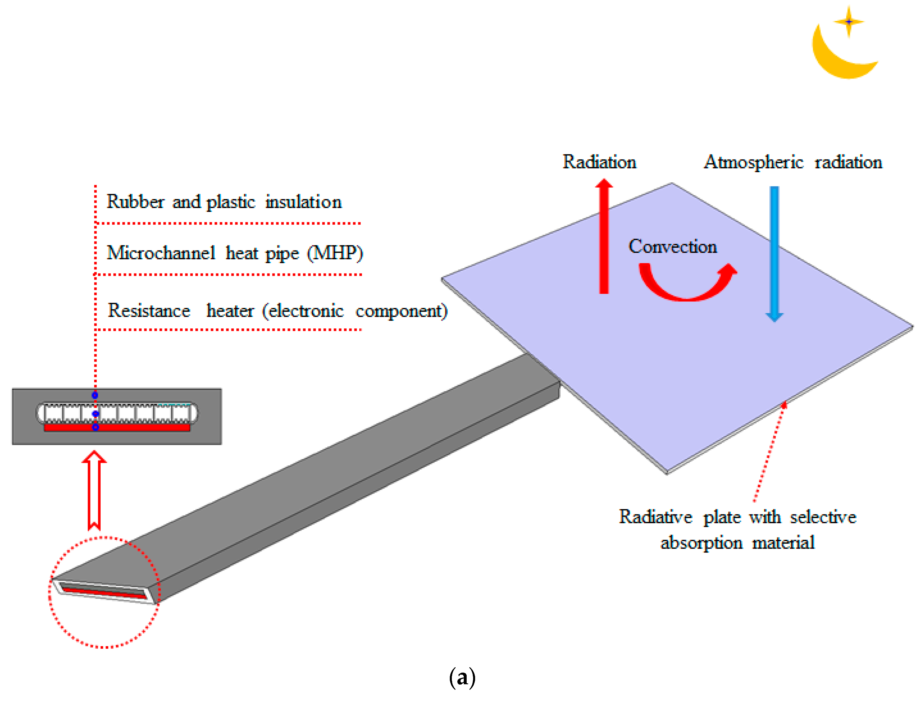
2. System Description

Figure 1 shows the basic structure of the proposed novel heat dissipation system (hereinafter referred to as the MHP-RC system) that can release the heat generated by electronic components. The MHP-RC system was made up of an MHP, radiative plate with selective absorption material, and electronic components. The electronic components were installed on the evaporation side of the MHP in the MHP-RC system, which is fixed by a cover plate; meanwhile, the radiative plate was stuck with the spectrally selective absorbing material and was installed on the condensation side. Furthermore, the selective absorption material was characterized by a lower emissivity in the solar irradiation band (0.25–2.5 μm) in the daytime and a higher reflectivity in the long-wavelength band in the nighttime, especially in the atmospheric window band with the wavelength of 8–13 μm [25,27]. It is also worth mentioning that heat transfer started when the temperature of the MHP evaporation side was higher than that of its condensation side because the MHP is a gravity type heat pipe. Thus the solar heat could not be transferred to the electronic components via the phase transition of the MHP during the daytime, and only received heat transfer through heat conduct. Additionally, for the convenience of drawing, the MHP-RC system in Figure 1b is placed horizontally. In fact, the radiation plate needs to tilt up slightly to ensure the normal operation of the MHP in the proposed system. Last but not least, the heat dissipation of the electronic components often needs to work continually to maintain stability within the system. A temperature monitoring system was set up to control the dissipation mode. Once its temperature exceeded the threshold value, the MHP-RC system heat dissipation mode switched to the forced heat dissipation mode.

3. Theoretical Models

To test the cooling performance of the MHP-RC system conveniently, the electronic components (hereinafter referred to as components) was simulated using a resistance heater to heat the MHP evaporation side in this paper. The MHP evaporation side and the resistance heater were wrapped by thermal insulation material to ensure that all the generated heat would be dissipated by the radiative plate.

3.1. Heat Balance of the Radiative Plate

A mathematical model based on the law of conservation of energy was built to analyze the performance of the system. Some assumptions were made to simplify the complex process of heat conversion and heat transfer in the operation of the system without losing significant accuracy. The detailed assumptions were as follows:
(1)
The physical property parameters of the radiative plate were constant.
(2)
It was assumed that the magnitude of the wind speed and air relative humidity were constant owing to the little fluctuation at nighttime.
(3)
The energy conservation equation could be considered as a two-dimension unsteady state because of the 1 mm thickness of the radiative plate.
(4)
Ignoring the radiant heat transfer between the back of the radiative plate and the ground, the radiative plate had a high reflectivity on the back.
The size of the radiative plate is shown in Figure 2, and it can be seen that the radiative plate was divided into two sections: the blue part represents the heat dissipation area where convection and radiation took place, and the red part represents the area heated by the MHP.
According to the heat balance, the energy conducted by the radiative plate and boundary condition can be given as Equations (1) and (2):
ρ b c b d b T t = k b d b 2 T x 2 + k b d b 2 T y 2 + q 0 ,
Boundary condition of the radiative plate:
T x | x = 0 , a = T x | x = 0 , b = 0 ,
Initial condition:
T | t = 0 = T i n i t ,
where ρb, cb, db, kb, a, b is the density, specific heat, thickness, thermal conductivity, length, and width of the radiative plate, respectively; and Tinit is the initial temperature of the radiative plate, which is equal to the temperature at first moment of the experiment. According to Figure 3, the internal heat flux q 0 can be expressed as Equation (4):
q 0 = q h b + q s q c q r ,
where qhb, qs, qc, and qr are calculated using Equations (5)–(8), respectively. qhb is the heat flux from the microheat pipe to the radiative plate, qs is the absorbed atmospheric radiation from the aerosphere to the radiative plate, qc is the convective heat flux from the radiative plate to the ambient air, and qr is the radiant heat flux from the radiative plate to the outer environment. It is noted that qhb is equal to 0 when the region of the radiative plate belongs to the zero-dissipation region, and qhb is expressed as Equation (4) when the region belongs to the zero-heating region.
q h b = T h e T R h b ,
q c = h c ( T a T ) ,
q r = ε ( T ) δ T 4 X ,
q s = ε ( T ) δ T s 4 X ,
where The is the evaporation side temperature of the MHP, Ta is the ambient temperature, Rhb is the contact thermal resistance between the MHP and the radiative plate, δ is the Stefan-Boltzmann constant and is equal to 5.67 × 10⁻⁸ W∙m−2·K−4, hc is the convective coefficient, X is the view factor of the radiative plate to the sky, ε ( T ) is the hemispherical emissivity, and Ts is the sky temperature. According to the literature [28,29,30], the hc, X, and ε ( T ) are expressed as given in Equations (9)–(11):
h c = 5.7 + 3.8 v ,
X = 1 + cos θ 2 ,
ε ( T ) = 0 ε λ ( λ , T ) E λ , b ( λ , T ) d λ E b ( T ) ,
where v is the wind speed, θ is the angle between the radiative plate and the horizontal plane, ε λ ( λ , T ) is the spectral hemispherical emissivity of the radiative plate, E λ , b ( λ , T ) is the spectral radiation power of the blackbody, and E b ( T ) is the full wavelength spectral radiation power of the blackbody.
According to the literature [31,32], Ts in Equation (8) is expressed as Equations (12)–(16):
T s = ( C a ε s ) 0.25 T a ,
C a = 1 + 0.0224 n 0.0035 n 2 + 0.00028 n 3 ,
ε s = 0.711 + 0.56 ( T d 273.15 100 ) + 0.73 ( T d 273.15 100 ) 2 + 0.013 cos ( 2 π t m 24 ) ,
T d = C 3 ln ( R H ) + C 1 C 2 [ ln ( R H ) + C 1 ] ,
C 1 = C 2 T a C 3 + T a ,   C 2 = 17.08085 ,   C 3 = 234.175 ,
where Ca is the cloudiness coefficient; n is the total opaque cloud amount (0 for clear sky, 10 for overcast sky), which can be obtained from the Typical Meteorological Year (TMY)data in the simulation; RH is the relative humidity of the ambient air; tm is the number of hours from midnight in solar time; and C1, C2, and C3 are constants.

3.2. Heat Balance of the MHP

According to the high thermal conductivity of the MHP [33,34], the MHP calculation can be solved using the lumped parameter method, which was verified by experimental results, as seen in Section 4.3.3. The MHP heat balance equation is given as Equations (17)–(19):
M h e c h e T t = Q h e + A h e T a T R i + 1 / h c + k h e A h e ( T h c T ) ,
M h c c h c T t = A h b T b T R h b + A h c T a T R i + 1 / h c + k h c A h c ( T h e T ) ,
R i = d i k i ,
Initial condition:
T | t = 0 = T i n i t ,
where Mhe(hc), che(hc), khe(hc), and Ahe(hc) are the mass, specific heat, thermal conductivity, and area of the evaporation side (condensation side) of the MHP, respectively; Ahb is the contacted area between the MHP and the radiative plate; Ri, di, and ki are the thermal resistance, thickness, and thermal conductivity of the thermal insulation material, respectively; Qhe is the heating power of the electronic component, which is supplied by the resistance heater; and Tinit is the same as the Equation (3) above.

3.3. Evaluation of Energy Saving

In order to evaluate the heat dissipation performance of the radiative plate, it was essential to calculate the amount of heat dissipation by the radiative plate through convection and sky radiative cooling [35]. According to above Equations (6)–(8), we computed the total heat dissipation of the radiative plate, which is expressed as Equation (21):
Q t = ( q c + q r q s ) d σ ,
where Qt is the total heat dissipation of the radiative plate, σ is the micro-area of the radiative plate, and the other parameters are the same as mentioned above.

4. Experimental Investigation

4.1. Fabrication of Radiative Plate

It is well known that effect of the radiative cooling is very limited because the solar radiation intensity is much higher than the radiative cooling power during the daytime, and therefore, the heat dissipation is not considered in the experiment [28]. However, it was hoped that less solar radiation enters the radiative plate to prevent the absorbed heat from conducting into the electronic component. Thus, the radiative plate was characterized by an absorptivity of 0 in the daytime and an emissivity of 1 in the nighttime, which is referred to as an ideal radiator, and the emissivity is shown in Figure 4. It can be seen that the absorptivity of the solar radiation band (0.25–2.5 μm) was 0, while the emissivity of other bands (2.5–25 μm) was 1; that is to say, the solar radiation heat was completely reflected in the daytime, and the radiative plate heat was completely radiated in the nighttime. However, it was not possible to make the radiative plate into an ideal radiator due to the limitation of the available material and technology.
To this end, the acrylic resin, curing agent, and thinner were blended and mixed according to the volume ratio of 2:1:1 based on the research of Bagiorgas and Mihalakakou [36,37]. A soft brush was used to evenly coat the mixture on the 1-mm-thick aluminum plate, and another layer was painted in the same way after drying once again, whose fabrication process is shown in Figure 5a. It was essential to employ DUV-3700 UV-Vis-NIR spectrophotometer (Shimazu, Japan) and Bruker Equinox 55 Fourier transform mid-infrared laser (Bruker, Germany) to measure its spectral reflectivity after the radiative plate had been fabricated, and the measured results are shown in Figure 6. The figure shows that the emissivity was 0.311 in the solar band (0.25–3 μm), 0.916 in the atmospheric window (0–3 μm), and 0.829 and 0.904 in the other two bands (3–8 μm, 13–25 μm), respectively. The results show that the radiative plate had a high emissivity in the middle- and long-wave bands, which could radiate more heat to the outdoor environment. Notably, the above two experimental instruments measure the reflectivity of the radiative plate ( ρ λ , and the absorptivity of the radiative plate ( α λ ) can be calculated using Equation (22) because of the 0 spectral transmittance [38]:
α λ + ρ λ = 1 ,
According to Kirchhoff’s law, the emissivity of the radiative plate is equal to its absorptivity, and the calculated results are shown in Figure 7. It can be concluded from Figure 4 and Figure 6 that the emissivity of the radiative plate was close to that of the ideal radiative plate. It should be noted that the heat pipe did not work because the radiation plate absorbed solar heat during the daytime, causing its condensation temperature to be greater than its evaporation temperature, and heat was only transferred through heat conduction of the material itself.
As shown in Figure 7, the average emissivity of the radiative plate was calculated at different temperatures according to Figure 6 and Equation (11). The results show that the emissivity/absorptivity of the radiative plate decreased with the increase of its temperature. The reason was that the maximum monochromatic emissivity moved to the short wavelengths when the temperature of the radiative plate increased, while the emissivity of the short wavelengths was relatively lower than other wavelengths. It can also be seen from Figure 7 that the maximum emissivity at 240 K was due to the fact that the spectral peak radiant power occurred in the range around of 10 μm (atmospheric window, 8–13 μm), and the emissivity of the radiative plate was also the highest in this band. Additionally, at natural conventional temperatures (300 K), the emissivity of the radiative plate was about 0.908, which indicates that the radiative plate coated with acrylic resin had a good emissivity to the sky.
According to Equation (21), the heat dissipation power of the radiative plate was computed when Ta = 25 °C, as revealed by Figure 8. Furthermore, it can be seen that the heat dissipation power of the radiative plate increased with the increase of temperature difference between the radiative plate surface and the ambient surroundings, mainly because the temperature difference increased and the convective heat transfer increased. We also found that the lower the equivalent temperature of the sky, the greater the heat dissipation power when the temperature difference between the radiative plate and the ambient air was the same. It can be interpreted as the lower the equivalent temperature of the sky, the better the effect of the radiative plate on the sky RC. The proposed radiative plate with a 200 W/m2 dissipation power at the ambient temperature (25 °C) and having only a surface area of 0.0012 m2 (400 mm × 300 mm) allowed for removing heat equivalent to a net cooling load of 0.24 kWh for the nighttime between 20:00 and 06:00 the next day. In other words, the radiative plate heat dissipation mode was enough for small-scale electronic component heat dissipation in the nighttime.

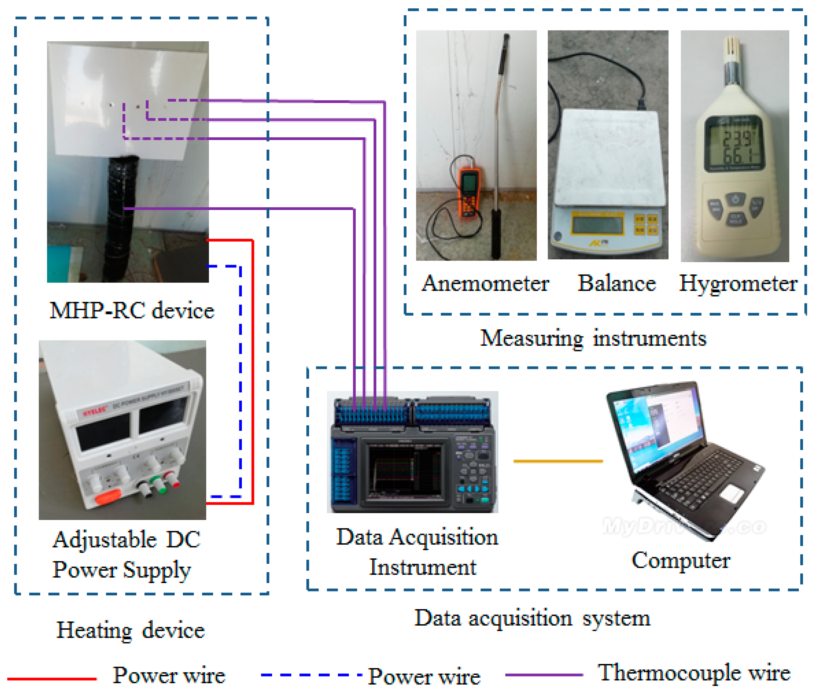
4.2. Testing Rig Description

In order to test the dissipation heat performance of the novel MHP-RC system, a simple testing rig was built, as shown in Figure 5b. The testing unit consisted of five components: the MHP, radiative plate, rubber and plastic insulation material, resistance heater and DC power supply, and resistance heater made using a resistance and silicone. A sticky resistance heater was attached to the evaporation side of the MHP, and a 24 V adjustable DC power supply was used to supply power to the resistance heater, which could adjust the voltage (or current) to meet the needs of simulating different heating powers. The MHPs were purchased from Nanjing GERR Electronic Technology Co. Ltd. (Nanjing, China), and its working fluid was acetone. Additionally, the evaporation side of the MHP and the resistance heater were insulated using 20-mm-thick rubber and plastic to ensure that the heat from the resistance heater was released directly from the radiative plate. The radiative plate was fixed on the condensation side of the MHP, and high thermal conductivity silicone grease was coated between them to reduce the contact thermal resistance. It should be emphasized that the adopted MHP in this paper belonged to a gravity-type heat pipe, and the MHP should tilt upward to ensure its normal operation during an experiment. The material parameters of the testing rig are shown in Table 1.
Four copper-constant-copper thermocouples were arranged in order to measure the temperature of the MHP-RC system, and the specific positions and spacings are shown in Figure 2 and Figure 9. It can be seen that the thermocouples were arranged along the center line of the long side of the radiative plate because the entire radiative plate was symmetrical with the MHP. Thus, it was only necessary to measure one side of the radiative plate during the temperature measurement. Two thermocouples (marked as A and B) were arranged along the center line of the long side, and another two thermocouples (marked as C and D) were placed in the MHP in order to verify whether the MHP had temperature uniformity during the experiment; one thermocouple was also required to measure the ambient temperature. All thermocouple values were collected using a HIOKI LR840-21 data acquisition instrument (HIOKI, Japan) every 60 s. The wind speed was measured using a hand-held hot wire anemometer (Taishi, Taiwan China). The mass of the MHP was measured with an electronic balance, and the relative humidity of the ambient air is measured with a GM1360A hygrometer (Shenzhen, China). The accuracy of all measuring instruments is shown in Table 2.

4.3. Fabrication of Radiative Plate

4.3.1. Analysis of the Experimental Uncertainty

To better verify the reliability of the experimental data, the uncertainty of parameters should be calculated. The uncertainty of the direct measurement parameters in the experiment is shown in Table 2, such as the temperature, relative humidity, wind speed, current, and voltage. The uncertainty of the indirect measurement parameters in the experiment is shown as Equation (23) [39]:
Δ Q Q = ( f x 1 ) 2 ( Δ x 1 y ) 2 + ( f x 2 ) 2 ( Δ x 2 y ) 2 + + ( f x n ) 2 ( Δ x n y ) 2
The function (f) is a function of the independent variable (xi), and Δ x i is the absolute error of the variable (xi). We calculated that the uncertainty of the radiative plate heat dissipation (Q) was 3.8% according to the above formula, which showed that the experimental method and data were reliable and accurate.

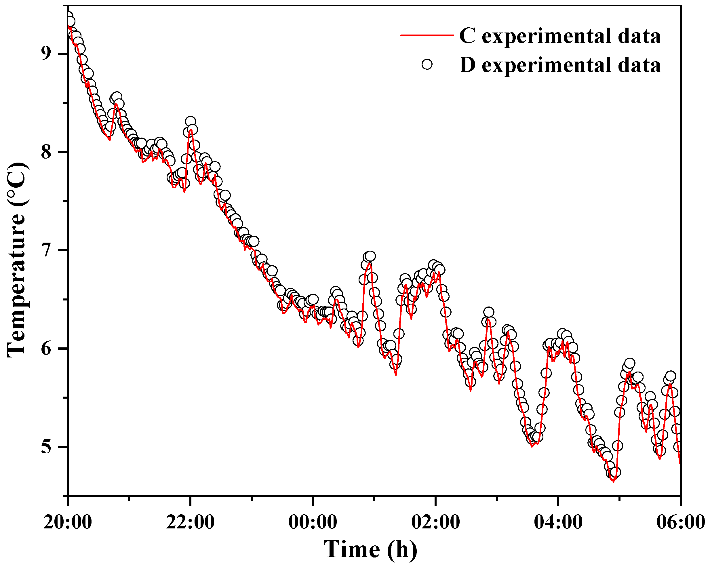
4.3.2. The Error of Experiment and Calculation

In order to investigate the heat dissipation performance of the MHP-RC system, the experiment was carried out for three nights of experimental testing because RC is difficult to achieve during the daytime [28]. We selected a clear night sky (20:00 on 23 January 2019 to 06:00 the next morning) for a total of 10 h, and a 6.5 W heating power was supplied by the resistance heater, where the 6.5 W heating power was the common generated heating power of the electronic component. The theoretical model energy equation of the MHP-RC system was solved using MATLAB R2016a based on weather data, and the calculated flow chart is shown in Figure 10. Coupled thermal and mass equations for each node were numerically discretized using the implicit method. The time step was set as 60 s, and all parts were meshed with 1 mm by 1 mm grids.
To better calculate the error between the experimental data and the calculated values, the root mean square error (RMSE) and mean absolute error (MAE) were used to evaluate the accuracy of the model, which are expressed as Equations (24) and (25) [40,41]:
RMSE = 1 n i = 1 n ( T s i m , i T exp , i ) 2 ,
MAE = 1 n i = 1 n | T s i m , i T exp , i | ,
where n represents the number of measurements made during the testing, and Tsim and Texp are the calculated value and experimental data, respectively.
Figure 11 shows the temperature variation of points B and C (temperature monitoring points) with time, the temperatures of which are relatively close. The RMSE and MAE were computed based on Figure 11, as shown in Table 3, and the results show that the maximum RMSE was merely 0.48 °C while the MAE was only 0.34 °C, which indicates that the theoretical value was in good agreement with the measured value. We therefore considered that the theoretical model could solve the heat transfer of the proposed MHP-RC system very well. It should be noted that the obtained RMSE and MAE were the weather data from one night of 23 January to the next morning.
Figure 12 shows the difference between the simulated value and the experimental value at point A (temperature monitoring point) of the radiative plate. The results show that the maximum difference between the experimental value and the simulated value was 1.98 °C, and the average value differed by 0.25 °C, which indicated that the simulated values are trustworthy. It is also evident from Figure 12 that the temperature at point A of the radiative plate was lower than the ambient air temperature, with the maximum temperature difference being 2.91 °C lower and the average temperature being 1.62 °C lower. It indicated that the sky radiative cooling was higher than the convective heat dissipation at point A, where the convective heat transfer made the air exothermic to the radiative plate. As is known, the heat dissipation mode on the left side of the point A was the same as the point A. Certainly, the heat transfer mode was not beneficial to the heat dissipation of the component, which was the heat transfer from the air to the radiative plate.

4.3.3. The Temperature of the MHP

As described in Figure 13, the MHP had very similar temperature values at points C and D, where point C was placed in the evaporation section, and point D was in the condensation section. It can be seen that the temperature difference between the two was small at merely 0.1 °C, and the results indicated that MHP was characterized by a high temperature uniformity performance. Accordingly, the temperature distribution of the MHP can be regarded as an isothermal body in theoretical modeling. It is therefore reasonable to use the lumped parameter method for the MHP discussed in Section 3.2 above.

5. Results and Discussion
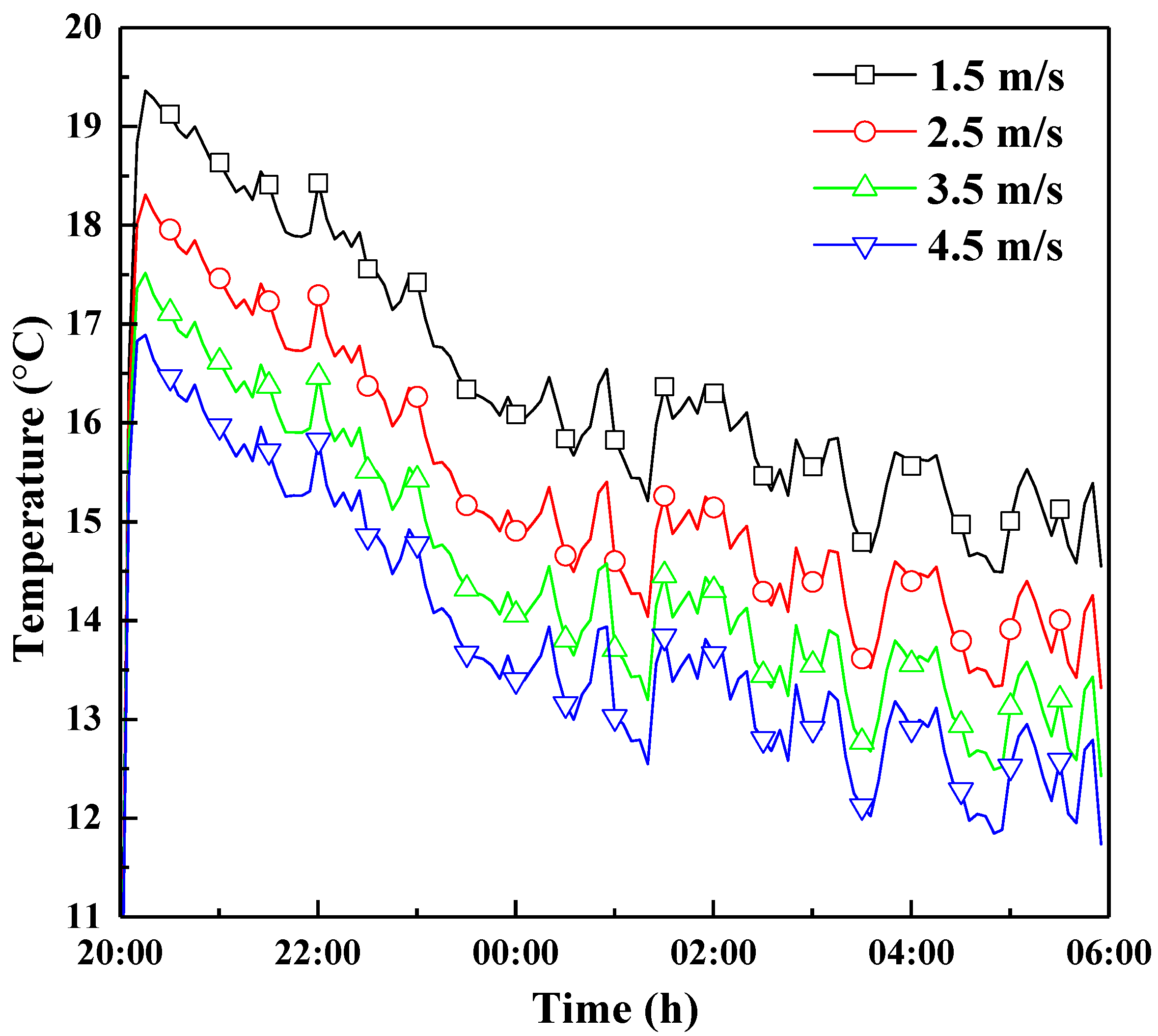
The above analysis was based on experimental and theoretical research under a specific weather condition. However, it will be affected by many parameters in the actual application, such as wind speed, relative humidity, cloudiness coefficient, power of the component, the radiative plate geometry, and tilted angle. The analysis of the effect of the above parameters on the surface temperature of the MHP-RC is presented in this section, and outdoor weather parameters were taken from the values of Section 4.3.2, which was the data of 23 January 2019. It is mentioned that if the parameter values are not specified in the next sections, all parameter values are shown in Table 4.

5.1. Wind Speed

As is known, the ambient wind speed affects the magnitude of the convective coefficient, and the larger the value, the more the heat dissipates toward the outdoor environment. Figure 14 shows the MHP variation tendency of temperature with wind speed. It should be emphasized that the resistance heater heated with a constant heat flux in the experiment, and the MHP was closely combined with the resistance heater surface, so the trend of the temperature variation of the heater and the MHP surface tended to be consistent, which is shown by a linear change. Therefore, the MHP temperature could be regarded as the surface temperature of the electronic component (hereinafter the same). It was found that the higher the outdoor wind speed, the lower the component surface temperature, which indicated that the convective heat transfer was larger, and the heat of convection heat dissipation was greater. In addition, we can also draw a conclusion from Figure 14 that the decrease of temperature became smaller with the increase of wind speed, mainly because the surface temperature of the component decreased to a certain threshold and was close to the outdoor ambient temperature. It was therefore of little significance to the lowering of temperature if the environmental wind speed was blindly increased.

5.2. Cloudiness Coefficient

The cloudiness coefficient (Ca) represents a parameter of the degree of sunny weather and is classified into 10 levels. A cloudiness coefficient of 0–2 denotes clear sky, 3–7 denotes common weather, and 8–10 is cloudy or overcast sky. It is seen in Figure 15 that the component surface temperature increased as the cloudiness coefficient increased. According to Equations (12) and (13), the higher the cloudiness coefficient, the greater the sky temperature, and the ability of the radiative plate to radiate into the sky is weakened, so the higher the surface temperature of the equipment is. However, the surface temperature of the component increased slightly, e.g., the cloudy weather (Ca = 9) was 0.8 °C lower than the sunny weather (Ca = 1), mainly because the net radiation heat transfer coefficient was lower.

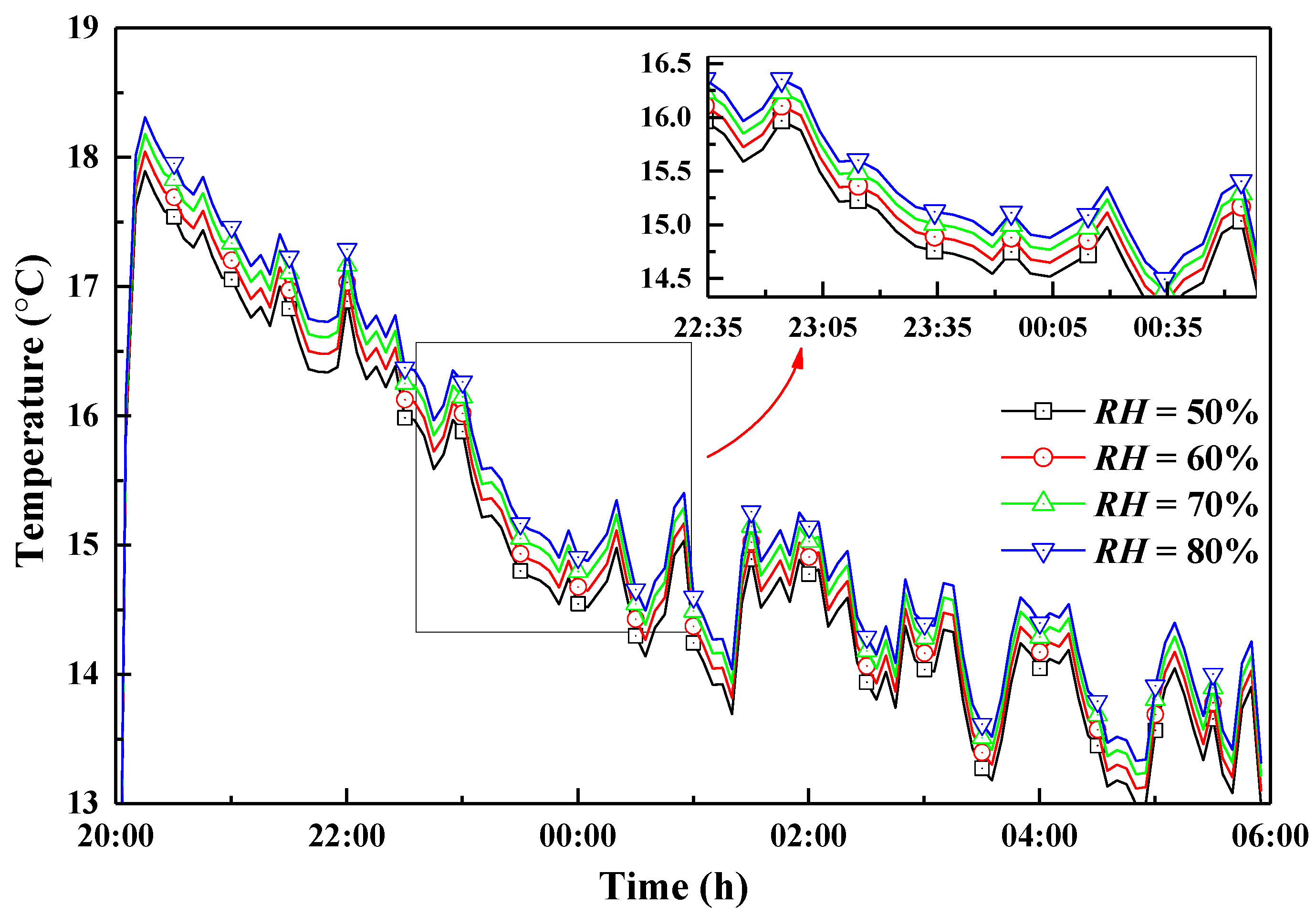
5.3. Relative Humidity

The relative humidity (RH) is the ratio of the vapor pressure of water vapor to the pressure of saturated water at the same temperature in the atmosphere, which reflects the amount of atmospheric water vapor. As shown in Figure 16, it can be seen that the higher the RH, the higher the component surface temperature. A possible explanation is that the greater the RH, the greater the water vapor content, the higher the equivalent sky temperature, and the lower the radiation by the radiative plate to the sky. Figure 16 also shows that RH had little effect on the component surface temperature; i.e., the maximum temperature difference of the component surface was merely 0.4 °C when RH was 80% and 50%, respectively. The results show that the influence of RH on RC was limited.

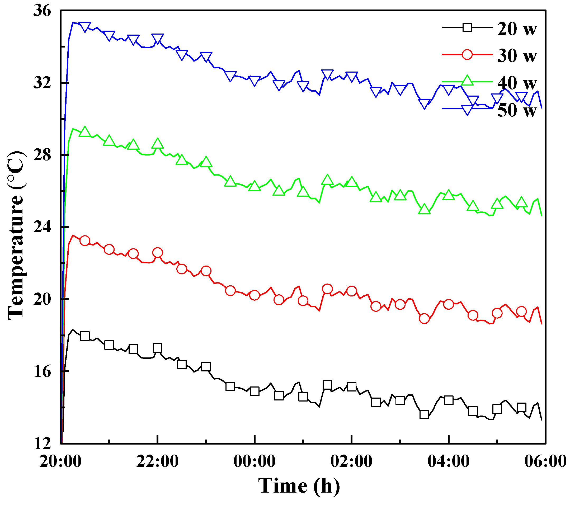
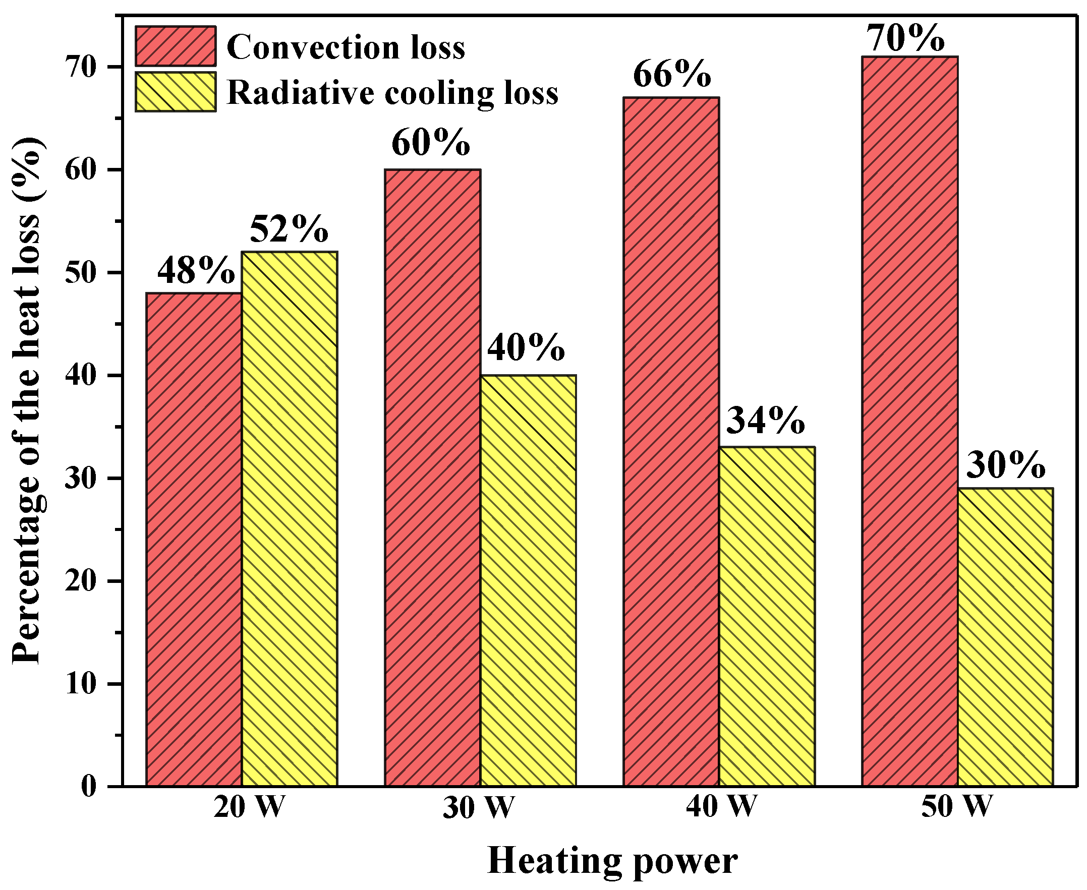
5.4. Power of the Resistance Heater

In order to better investigate the influence of the heat output on the temperature of the component surface, its surface temperature was calculated under various heating powers. As shown in Figure 17, we found that the higher the heat dissipation by the component, the higher the surface temperature, which is consistent with common sense. It is essential to investigate the temperature of the component surface at different heat outputs in practical applications. It was assumed that the highest operating temperature of the component was 40 °C, and the temperature of the component surface was below 40 °C when the heat output was below 50 W, according to Figure 17. That is, the 50 W of heat output could be dissipated outward through the MHP-RC system without consuming any energy.
According to Equation (21), the proportion of convection and radiation obtained under different heating powers is shown in Figure 18. It can be seen that when the heat output was small (20 W), the convection and radiation each accounted for half of the heat loss. With the increase of the heat output, the proportion of convection increased while radiation decreased. The convective dissipation and radiation dissipation each accounted for 70% and 30% of total heat dissipation when the heat output reached 50 W. As is known, the temperature difference between the radiative plate and the ambient air was small when the heating output was low, while its temperature difference was large when the heating output was high. The convective coefficient was greater than the radiative coefficient, so the proportion of convective heat transfer was larger than that of the radiative heat transfer.

5.5. Relative Plate Size
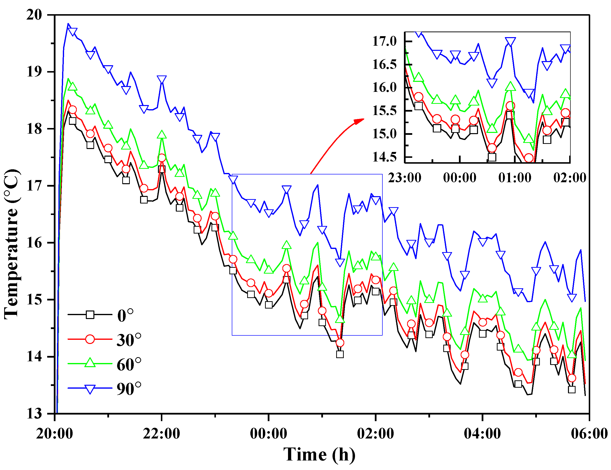
As shown in Figure 19, it was found that the longer the length of the radiative plate, the lower the component surface temperature, which indicated that the MHP-RC was characterized by good heat dissipation. However, it seems that the temperature of the component surface varied very little when the length of the radiative plate exceeded 400 mm. That is, it was not obvious that the surface temperature was reduced through increasing the length of the radiative plate. This can be interpreted as the thermal resistance of the radiative plate being relatively small because of its thinner thickness (1 mm) and high thermal conductivity (237 W m−1 K−1). Figure 20 shows the effect of the width on the component surface temperature. It indicates that the width of the radiative plate was larger, and its surface temperature was lower. Similarly, the reduction of the component surface temperature was less when the width exceeded 400 mm, whereas the heat dissipation effect was better than that when increasing its length. It should be emphasized that the component surface temperature variation in Figure 19 and Figure 20 were based on a heat output of 20 W. The heat output of 50 W and 100 W were also calculated, and the results show that the trend of temperature variation was similar to those of the above two figures. For economic reasons, it is suggested that the size of the radiative plate should be 400 mm × 400–500 mm (length × width) matched by a single MHP (width: 60 mm). It is better to increase the number of MHPs if the size of the radiative plate exceeds this dimension.

5.6. Tilted Angle

As shown in Figure 21, it can be seen that the temperature of the component surface decreased with the increase of the tilted angle of the radiative plate. The component surface temperature was the lowest when the radiative plate was placed approximately horizontally (>0°), whereas the surface temperature was the highest when placed vertically, with the maximum difference between the two forms being 1.7 °C due to the fact that the radiative plate “saw” a lower proportion of the sky. Therefore, it is recommended that the radiative plate be placed approximately horizontally. When the site conditions were not satisfied, the tilted of the radiative plate was kept within 30° of the horizontal plane, which had little effect on the component surface temperature drop.

5.7. Summer Night Heat Dissipation

The obtained results in the above sections were all conducted in winter. Figure 22 shows the temperature variation of ambient air and the component surface, where the used weather data was measured on a night in July (i.e., in summer). It is indicated that the variation trend of the component surface temperature was almost the same as that in winter, which was about 10 °C higher than the ambient temperature. Additionally, the component surface temperature was higher than that in winter because the ambient temperature in summer was higher than that in winter. Certainly, the heat dissipation power of the component was lower than that in winter due to the high ambient temperature.

6. Conclusions

A novel MHP-RC system was proposed and tested using experiments. The field-tested results agree well with the mathematical models. The obtained experimental and theoretical results were as follows:
(1)
The daytime emissivity of the radiative plate made using white paint was 0.311, and the nocturnal emissivity was about 0.908; the average emissivity of the radiative plate was 0.916 when the wave band was in the atmospheric window.
(2)
The parameters had a certain influence on the heat dissipation of the radiative plate, such as the wind speed, cloudiness coefficient, relative humidity, and power of resistance heater. Among these, wind speed had a greater impact on reducing the component surface temperature, which indicates that radiation heat dissipation was less than convection heat dissipation.
(3)
The influence of the width of the radiative plate was greater than that of the horizontal length on the heat dissipation. The recommended dimensions of the radiative plate was 400 mm × 400–500 mm (length × width) matched by a single MHP (width: 60 mm). In order to ensure a large radiant heat, the titled angle of the radiative plate should be kept within 30° of the horizontal plane.
In this paper, the heat dissipation of the MHP-RC system in the nighttime was investigated. In the future, it is necessary to study the effect on the heat dissipation of the radiative plate during the daytime. In summary, the novel MHP-RC system was helpful at providing heat dissipation for electronic components, and it played an important role in energy conservation.

Author Contributions

Conceptualization, W.H. and D.S.; software, Z.H. and H.Y.; formal analysis, C.Y. and Q.J.; investigation, C.Y., S.Z., and P.Y.; writing—original draft preparation, C.Y. and H.Y.; writing—review and editing, C.Y., H.C., and S.Z.; supervision, W.H. and D.S. All authors have read and agreed to the published version of the manuscript.

Funding

This research was funded by the Science and technology cooperation project of Qinghai Province, grant number 2017-HZ-807; Beijing Advanced Innovation Center for Future Urban Design, grant number UDC 2016040200; and was also supported by the Anhui Natural Science Foundation Youth Project, grant number JZ2019AKZR0248.

Acknowledgments

The authors wish to express their thanks to the very competent reviewers for the valuable comments and suggestions.

Conflicts of Interest

We declare that no conflict exists in the submission of this manuscript, and the manuscript is approved by all authors for publication. I would like to declare on behalf of my co-authors that the work described was original research that has not been published previously, and not under consideration for publication elsewhere, in whole or in part. All the authors listed have approved the manuscript that is enclosed. We believe that this manuscript is interesting to general readers of your journal.

Nomenclature

alength (m)
Aarea (m2)
bwidth (m)
cspecific heat capacity (J kg−1 K−1)
Cacloudiness coefficient
dthickness (m)
Eradiant power (W/m2)
hheat transfer coefficient (W m−2 K−1)
kthermal conductivity (W m−1 K−1)
Mmass (kg)
ntotal opaque cloud amount
qheat flux (W m−2)
Qheat output, (W)
Rthermal resistance (K m2 W −1)
RHrelative humidity (%)
Ttemperature (K)
ttime (h)
vwind speed (m s−1)
Xangle factor
Subscripts
aambient air
bradiative plate or blackbody
cconvention
ddew point
eelectronic component
hmicrochannel heat pipe
hbbetween MHP and radiative plate
heevaporation side of the MHP
hccondensation side of the MHP
iinsulation material
mmidnight
rradiant
ssky
ttotal
0internal heat flux
Greek Symbols
α absorptivity
ρ reflectivity
λ wavelength
ε emissivity
θ angle (°)
δ Stefan-Boltzmann constant
σ micro-area of the radiative plate

References

  1. Miroshnichenko, I.; Sheremet, M.; Mohamad, A. The Influence of Surface Radiation on the Passive Cooling of a Heat-Generating Element. Energies 2019, 12, 980. [Google Scholar] [CrossRef] [Green Version]
  2. Bi, Y.; Wang, Y.; Ma, X.; Zhao, X. Investigation on the Energy Saving Potential of Using a Novel Dew Point Cooling System in Data Centres. Energies 2017, 10, 1732. [Google Scholar] [CrossRef] [Green Version]
  3. Bar-Cohen, A.; Kraus, A.D.; Davidson, S.F. Thermal frontiers in the design and packaging microelectronic equipment. Mech. Eng. 1983, 105, 53–59. [Google Scholar]
  4. Batunlu, C.; Albarbar, A. Real-time system for monitoring the electro-thermal behaviour of power electronic devices used in boost converters. Microelectron. Reliab. 2016, 62, 82–90. [Google Scholar] [CrossRef]
  5. Huang, X.; Shi, C.; Zhou, J.; Lu, X.; Xu, G. Performance analysis and design optimization of heat pipe sink with a variable height fin array under natural convection. Appl. Therm. Eng. 2019, 159, 11. [Google Scholar] [CrossRef]
  6. Nguyen, C.T.; Roy, G.; Gauthier, C.; Galanis, N. Heat transfer enhancement using Al2O3–water nanofluid for an electronic liquid cooling system. Appl. Therm. Eng. 2007, 27, 1501–1506. [Google Scholar] [CrossRef]
  7. Chang, Y.-W.; Chang, C.-C.; Ke, M.-T.; Chen, S.-L. Thermoelectric air-cooling module for electronic devices. Appl. Therm. Eng. 2009, 29, 2731–2737. [Google Scholar] [CrossRef]
  8. Lin, C.-N.; Jang, J.-Y.; Leu, J.-S. A Study of an Effective Heat-Dissipating Piezoelectric Fan for High Heat Density Devices. Energies 2016, 9, 610. [Google Scholar] [CrossRef] [Green Version]
  9. Mu, Y.-T.; Chen, L.; He, Y.-L.; Tao, W.-Q. Numerical study on temperature uniformity in a novel mini-channel heat sink with different flow field configurations. Int. J. Heat Mass Tran. 2015, 85, 147–157. [Google Scholar] [CrossRef]
  10. Tian, F.; Song, B.; Chen, X.; Ravichandran, N.K.; Lv, Y.; Chen, K.; Sullivan, S.; Kim, J.; Zhou, Y.; Goni, M.; et al. Unusual high thermal conductivity in boron arsenide bulk crystals. Science 2018, 361, 582–585. [Google Scholar] [CrossRef] [Green Version]
  11. Lee, H.E.; Lee, S.H.; Jeong, M.; Shin, J.H.; Ahn, Y.; Kim, D.; Oh, S.H.; Yun, S.H.; Lee, K.J. Trichogenic Photostimulation Using Monolithic Flexible Vertical AlGaInP Light-Emitting Diodes. ACS Nano 2018, 12, 9587–9595. [Google Scholar] [CrossRef] [PubMed]
  12. Lee, H.E.; Shin, J.H.; Park, J.H.; Hong, S.K.; Park, S.H.; Lee, S.H.; Lee, J.H.; Kang, I.S.; Lee, K.J. Micro Light-Emitting Diodes for Display and Flexible Biomedical Applications. Adv. Funct. Mater. 2019, 29, 14. [Google Scholar] [CrossRef]
  13. Sandesh, S.; Chougule, S.K.S. Thermal Performance of Nanofluid Charged Heat Pipe with Phase Change Material for Electronics Cooling. J. Electron. Packag. 2015, 137, 021004. [Google Scholar]
  14. Zhu, T.-T.; Diao, Y.-H.; Zhao, Y.-H.; Li, F.-F. Thermal performance of a new CPC solar air collector with flat micro-heat pipe arrays. Appl. Therm. Eng. 2016, 98, 1201–1213. [Google Scholar] [CrossRef]
  15. Chen, H.; Zhang, H.; Li, M.; Liu, H.; Huang, J. Experimental investigation of a novel LCPV/T system with micro-channel heat pipe array. Renew. Energy 2018, 115, 773–782. [Google Scholar] [CrossRef]
  16. Li, G.; Ji, J.; Zhang, G.; He, W.; Chen, X.; Chen, H. Performance analysis on a novel micro-channel heat pipe evacuated tube solar collector-incorporated thermoelectric generation. Int. J. Energy Res. 2016, 40, 2117–2127. [Google Scholar] [CrossRef]
  17. Weng, Y.-C.; Cho, H.-P.; Chang, C.-C.; Chen, S.-L. Heat pipe with PCM for electronic cooling. Appl. Energy 2011, 88, 1825–1833. [Google Scholar] [CrossRef]
  18. Wang, J.-C. Superposition method to investigate the thermal performance of heat sink with embedded heat pipes. Int. Commun. Heat Mass Transf. 2009, 36, 686–692. [Google Scholar] [CrossRef]
  19. Ye, H.; Li, B.; Tang, H.; Zhao, J.; Yuan, C.; Zhang, G. Design of vertical fin arrays with heat pipes used for high-power light-emitting diodes. Microelectron. Reliab. 2014, 54, 2448–2455. [Google Scholar] [CrossRef]
  20. Stafford, J.; Walsh, E.; Egan, V.; Walsh, P.; Muzychka, Y.S. A Novel Approach to Low Profile Heat Sink Design. J. Heat Transf. 2010, 132, 091401. [Google Scholar] [CrossRef]
  21. Krishna, J.; Kishore, P.S.; Solomon, A.B. Heat pipe with nano enhanced-PCM for electronic cooling application. Exp. Therm. Fluid Sci. 2017, 81, 84–92. [Google Scholar] [CrossRef] [Green Version]
  22. Behi, H.; Ghanbarpour, M.; Behi, M. Investigation of PCM-assisted heat pipe for electronic cooling. Appl. Therm. Eng. 2017, 127, 1132–1142. [Google Scholar] [CrossRef]
  23. Ezekwe, C.I. Performance of a heat pipe assisted night sky radiative cooler. Energy Convers. Manag. 1990, 30, 403–408. [Google Scholar] [CrossRef]
  24. Ao, X.; Hu, M.; Zhao, B.; Chen, N.; Pei, G.; Zou, C. Preliminary experimental study of a specular and a diffuse surface for daytime radiative cooling. Sol. Energy Mater. Sol. Cells 2019, 191, 290–296. [Google Scholar] [CrossRef]
  25. Zhao, B.; Hu, M.; Ao, X.; Chen, N.; Pei, G. Radiative cooling: A review of fundamentals, materials, applications, and prospects. Appl. Energy 2019, 236, 489–513. [Google Scholar] [CrossRef]
  26. Hu, M.; Pei, G.; Wang, Q.; Li, J.; Wang, Y.; Ji, J. Field test and preliminary analysis of a combined diurnal solar heating and nocturnal radiative cooling system. Appl. Energy 2016, 179, 899–908. [Google Scholar] [CrossRef] [Green Version]
  27. He, W.; Yu, C.; Yang, J.; Yu, B.; Hu, Z.; Shen, D.; Liu, X.; Qin, M.; Chen, H. Experimental study on the performance of a novel RC-PCM-wall. Energy Build. 2019, 199, 297–310. [Google Scholar] [CrossRef]
  28. Zeyghami, M.; Goswami, D.Y.; Stefanakos, E. A review of clear sky radiative cooling developments and applications in renewable power systems and passive building cooling. Sol. Energy Mater. Sol. Cells 2018, 178, 115–128. [Google Scholar] [CrossRef]
  29. Liu, Y.; Liu, J. Study of heat transfer coefficient at exterior building surface. J. Xi’an Univ. Archit. Technol. Nat. Sci. Ed. 2008, 40, 407–412. [Google Scholar]
  30. Holman, J.P. Heat Transfer, 10th ed.; Mcgraw-Hill Co. Inc.: New York, UY, USA, 2008; p. 383. [Google Scholar]
  31. Zhang, S.; Niu, J. Cooling performance of nocturnal radiative cooling combined with microencapsulated phase change material (MPCM) slurry storage. Energy Build. 2012, 54, 122–130. [Google Scholar] [CrossRef]
  32. Vall, S.; Castell, A. Radiative cooling as low-grade energy source: A literature review. Renew. Sustain. Energy Rev. 2017, 77, 803–820. [Google Scholar] [CrossRef] [Green Version]
  33. Li, G.; Zhang, G.; He, W.; Ji, J.; Lv, S.; Chen, X.; Chen, H. Performance analysis on a solar concentrating thermoelectric generator using the micro-channel heat pipe array. Energy Convers. Manag. 2016, 112, 191–198. [Google Scholar] [CrossRef] [Green Version]
  34. Gang, P.; Huide, F.; Tao, Z.; Jie, J. A numerical and experimental study on a heat pipe PV/T system. Sol. Energy 2011, 85, 911–921. [Google Scholar] [CrossRef]
  35. Meir, M.G.; Rekstad, J.B.; LØvvik, O.M. A study of a polymer-based radiative cooling system. Sol. Energy 2002, 73, 403–417. [Google Scholar] [CrossRef]
  36. Harrison, A.W.; Walton, M.R. Radiative cooling of TiO2 white paint. Sol. Energy 1978, 20, 185–188. [Google Scholar] [CrossRef]
  37. Bagiorgas, H.S.; Mihalakakou, G. Experimental and theoretical investigation of a nocturnal radiator for space cooling. Renew. Energy 2008, 33, 1220–1227. [Google Scholar] [CrossRef]
  38. Hu, M.; Zhao, B.; Ao, X.; Zhao, P.; Su, Y.; Pei, G. Field investigation of a hybrid photovoltaic-photothermic-radiative cooling system. Appl. Energy 2018, 231, 288–300. [Google Scholar] [CrossRef]
  39. Holman, J.; Gajda, W.J. Experimental Methods for Engineers; Mcgraw-Hill: New York, NY, USA, 1994. [Google Scholar]
  40. Willmott, C.J.; Matsuura, K. Advantages of the Mean Absolute Error (MAE) over the Root Mean Square Error (RMSE) in Assessing Average Model Performance. Clim. Res. 2005, 30, 79–82. [Google Scholar] [CrossRef]
  41. Chai, T.; Draxler, R.R. Root Mean Square Error (RMSE) or Mean Absolute Error (MAE)?—Arguments against Avoiding RMSE in the Literature. Geosci. Model Dev. 2014, 7, 1247–1250. [Google Scholar] [CrossRef] [Green Version]
Figure 1. The unit of the novel MHP-RC (radiative and convection) system: (a) the aerial view and the (b) overall structure chart.
Energies 13 00106 g001aEnergies 13 00106 g001b
Figure 2. The dimensions of the radiative plate and the layout diagram of the thermocouple.
Energies 13 00106 g002
Figure 3. Radiative plate heat flux diagram [25].
Energies 13 00106 g003
Figure 4. Variation of an ideal radiator’s emissivity/absorptivity with wavelength.
Energies 13 00106 g004
Figure 5. The assembly diagrams of testing rig (a) Fabrication of the radiative plate; (b) Fabrication of the MHP-RC device).
Energies 13 00106 g005
Figure 6. Variation of the measured radiator emissivity/absorptivity with wavelength.
Energies 13 00106 g006
Figure 7. The variation of the emissivity/absorptivity with radiative plate temperature.
Energies 13 00106 g007
Figure 8. The variation of the heat dissipation power with temperature difference between the radiative plate surface and the ambient surroundings.
Energies 13 00106 g008
Figure 9. The testing diagram of the testing rig.
Energies 13 00106 g009
Figure 10. The calculated flow chart of dynamic mathematical model of the radiative plate.
Energies 13 00106 g010
Figure 11. The comparison of experimental and simulated values of point B and C.
Energies 13 00106 g011
Figure 12. The temperature variation curves of the experimental and simulated values of point A and the ambient surroundings.
Energies 13 00106 g012
Figure 13. Temperature variation of the MHP evaporation and condensation sides with time.
Energies 13 00106 g013
Figure 14. Time-dependent variation of the component surface temperature with different wind speeds.
Energies 13 00106 g014
Figure 15. Time-dependent variation of the component surface temperature with different cloudiness coefficients.
Energies 13 00106 g015
Figure 16. Time-dependent variation of the component surface temperature with the different relative humidities.
Energies 13 00106 g016
Figure 17. Time-dependent variation of the component surface temperature with different heating outputs.
Energies 13 00106 g017
Figure 18. The proportion of convection and radiation to total heat dissipation with different heating powers.
Energies 13 00106 g018
Figure 19. Time-dependent variation of the component surface temperature with different lengths of the radiative plate.
Energies 13 00106 g019
Figure 20. Time-dependent variation of the component surface temperature with different widths of the radiative plate.
Energies 13 00106 g020
Figure 21. Time-dependent variation of the component surface temperature with different tilted angles.
Energies 13 00106 g021
Figure 22. Time-dependent variation of the component surface temperature and ambient temperature in summer/winter nighttime (65% RH).
Energies 13 00106 g022
Table 1. The material parameters of the testing rig.
ParameterNumerical
MHP
  Length0.8 m
  Width0.06 m
  Thickness0.004 m
  Mass0.245 kg
  Thermal conductivity23,000 W m−1 K−1
Radiative plate
  Length0.4 m
  Width0.3 m
  Thickness0.001 m
  Thermal conductivity237 W m−1 K−1
Rubber-plastic insulation material
  Thickness0.02 m
  Thermal conductivity0.034 W m−1 K−1
Table 2. The uncertainties of the measuring instruments.
Measuring InstrumentUncertainty
Copper-constant-copper thermocouple0.2–0.5 K
Hot wire anemometer±2%
Hygrometer±3% RH
Current ±1%
Voltage ±0.5%
Electronic balance 0.01 g
Table 3. The root mean square error (RMSE) and mean absolute error (MAE) of points B and C.
ParameterRMSEMAE
B0.480.34
C0.400.28
Table 4. Outdoor weather parameters and component power.
Wind SpeedCloudiness CoefficientRelative HumidityPower
2.5 m/s280%20 W

