Article

Five-Level T-type Cascade Converter for Rooftop Grid-Connected Photovoltaic Systems

by
Cristian Verdugo
1,‡,
Samir Kouro
2,†,‡,
Christian A. Rojas
2,*,†,‡,
Marcelo A. Perez
2,†,‡,
Thierry Meynard
3,‡ and
Mariusz Malinowski
4,‡
1
Electrical Engineering Department, Polytechnic University of Catalonia, 08222 Barcelona, Spain
2
Electronics Engineering Department, Universidad Técnica Federico Santa María, Valparaiso 2390123, Chile
3
Institut National Polytechnique de Toulouse, 31071 Toulouse, France
4
Institute of Control & Industrial Electronics, Warsaw University of Technology, 00-662 Warsaw, Poland
*
Author to whom correspondence should be addressed.
Current address: Av. España 1680, Valparaíso 2390123, Chile.
These authors contributed equally to this work.
Energies 2019, 12(9), 1743; https://doi.org/10.3390/en12091743
Submission received: 12 April 2019 / Revised: 29 April 2019 / Accepted: 30 April 2019 / Published: 8 May 2019

Abstract

:
Multilevel converters are widely considered to be the most suitable configurations for renewable energy sources. Their high-power quality, efficiency and performance make them interesting for PV applications. In low-power applications such as rooftop grid-connected PV systems, power converters with high efficiency and reliability are required. For this reason, multilevel converters based on parallel and cascaded configurations have been proposed and commercialized in the industry. Motivated by the features of multilevel converters based on cascaded configurations, this work presents the modulation and control of a rooftop single-phase grid-connected photovoltaic multilevel system. The configuration has a symmetrical cascade connection of two three-level T-type neutral point clamped power legs, which creates a five-level converter with two independent string connections. The proposed topology merges the benefits of multi-string PV and symmetrical cascade multilevel inverters. The switching operation principle, modulation technique and control scheme under an unbalanced power operation among the cell are addressed. Simulation and experimental validation results in a reduced-scale power single-phase converter prototype under variable conditions at different set points for both PV strings are presented. Finally, a comparative numerical analysis between other T-type configurations to highlight the advantages of the studied configuration is included.

1. Introduction

Rooftop photovoltaic (PV) energy conversion systems (less than 20 kW), have become a well-established technology in the industry. The most common configurations for single-phase grid-connected PV systems commercially found are the string, multistring and ac-module integrated topologies. Central and string inverters have been widely applied to manage and control PV energy systems [1]. Among the string topologies, the transformerless H5, H6, HERIC, neutral point clamped (NPC) and T-type NPC converters have been successfully commercialized [2]. In fact, multilevel inverters (MLI) are designed to produce a stepped voltage waveform by reducing the Total Harmonic Distortion (THD) and the voltage stress across semiconductor devices. Secondly, reduction of the output filter size and power footprint also permit an important improvement in terms of costs, weight and efficiency [3]. These technical features have led to the massive adoption of MLI over the last thirty years for high-power medium voltage (MV) motor drive applications. In the last years, three-level neutral point clamped (3L-NPC) converters have been used for interfacing PV systems into the grid, where a higher PV incorporation has brought substantial concerns on power efficiency, power quality and grid code compliance [1] as well as power grid services [4].
T-type neutral point clamped inverters (3L-TNPC), also known as neutral point piloted converters (3L-NPP), [5] have gained a wide presence in the industry sector due to several advantages as symmetrical loss distribution, higher overall efficiency, small footprints [6] and low harmonic injection in relation to the conventional 3L-NPC [7]. In fact, many manufactures such as Fuji, On Semiconductor, Mitsubishi and Semikron have commercial T-type legs used in central PV inverters and motor drive applications [8,9,10]. For the three-level inverter, based on the T-type leg, was presented thirty-five years ago for motor drives, with the bidirectional medium switch being realized with thyristors and improved with GTO-thyristors [11]. After some years, many configurations based on the well-known three-level T-type NPC leg can be found in the literature [12]. In [13] a five-level TNPC (5L-TNPC) was introduced, which corresponds to the parallel connection of two 3L-TNPC legs [14,15]. Furthermore, a variation of this configuration with reduced switches, also known as five-level hybrid T-type NPC (5L-HTNPC), was presented in the recent literature [16]. This topological variation is built with a 3L-TNPC leg and a two-level leg inverter, forming a five-stepped voltage waveform in the AC terminals.
In the literature there are two main possibilities for increasing the number of levels in the power converter field, which is by increasing the internal DC capacitors connected to a single DC source or by connecting several converters in the series at the AC side, in which each converter has an independent DC source. Focusing on the second alternative, cascade MLI can be developed by using symmetrical or asymmetrical voltage levels and by using different type of topologies such as: Full H-Bridge, 3L-TNPC converters or by performing a hybrid configuration [17]. Note that symmetrical cascade configurations have had a more industrial presence as the case of Cascade H-Bridge (CHB) converters [3] due to modulation and control simplicity compared with asymmetrical configurations [18]. In fact, in [19] a symmetrical nine-level T-type converter (9L-TNPC) is presented for motor drive applications, which is based on the cascade connection of two 5L-TNPC converters. The same number of levels can be generated with advanced hybrid topologies as presented in [6,12].
Considering the advantages and features previously presented regarding the 3L-TNPC and symmetrical cascaded configurations, this paper described and validated the 5L-CTNPC topology for rooftop PV applications by using a cascaded connection of two 3L-TNPC legs which was firstly introduced in [20] as a cascade 3L-TNPC converter. Thus, the advantages of symmetrical cascade configurations with multistring inputs are merged. Each 3L-TNPC converter can interface a dedicated DC bus, and consequently two separate maximum power point tracking (MPPT) algorithms are allowed to obtain the maximum power of each PV string. Note that the PV string of each module can be sized to handle half the entire PV string in the conventional 3L-TNPC converter, providing better MPPT efficiency since less modules are combined in a series per string. The main contribution of this paper is the experimental validation of a simplified control scheme to alleviate the power unbalancing mismatch between 3L-TNPC modules and to compensate capacitor voltage variations per each converter, which was presented earlier in [20]. Furthermore, a brief comparison between five-level voltage waveform converters based on the conventional 3L-TNPC is performed as a second contribution in terms of the main electrical features.
The rest of the document is organized as follows. In Section 2, a hardware description of the proposed converter, switching states and implemented modulation is presented. In Section 3, a simple stationary reference-frame voltage-oriented control and a voltage control loop to compensate a possible power unbalance operation are included. Then, in Section 4, simulation results and experimental verification of the proposed multilevel converter and its control system behavior are added. Furthermore, a brief comparison with the 5L-TNPC and 5L-HTNPC is performed to highlight the main advantages of the proposed configuration. Finally, in Section 5, the conclusions of the paper summarize the work done.

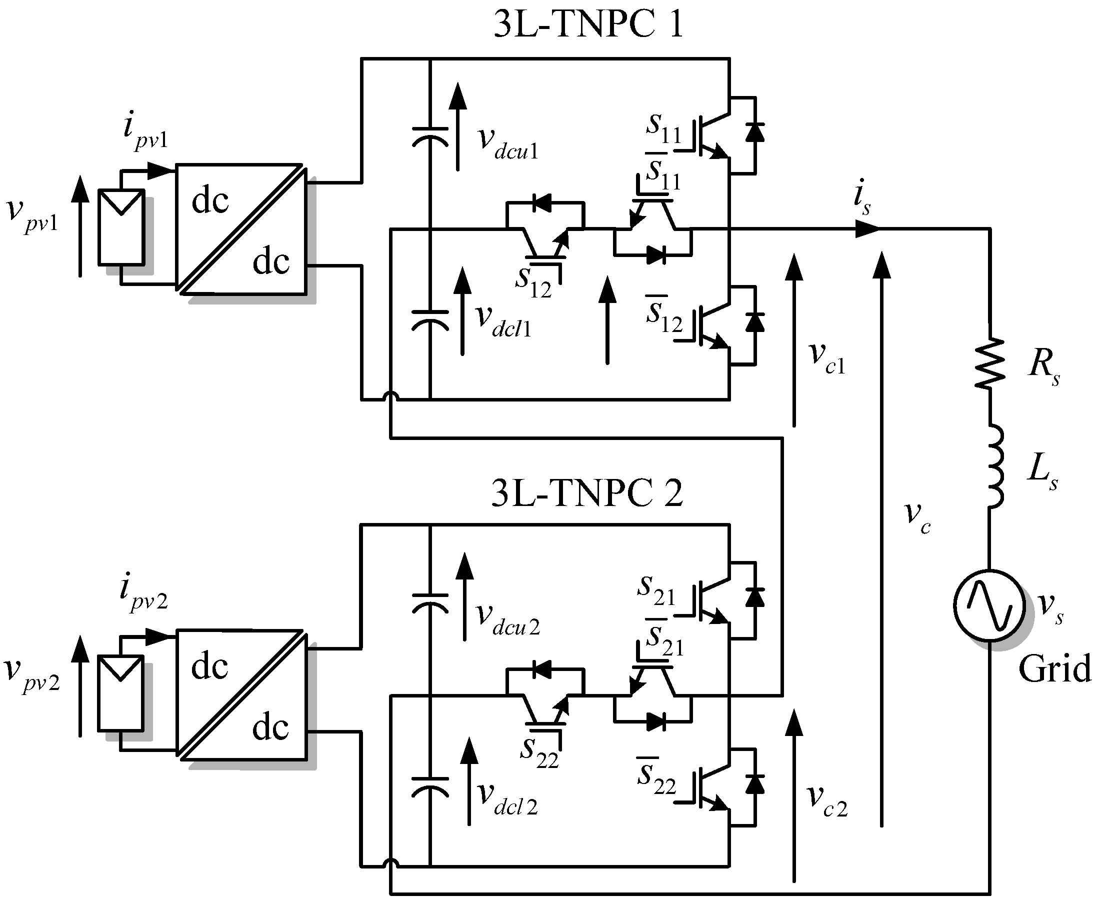
2. The 5L-CTNPC Converter Topology

The power topology of the analyzed cascade 5L-CTNPC for a rooftop grid-connected PV system is depicted in Figure 1. The configuration is composed of a series connection of two 3L-TNPC legs, where each of them is built with two conventional IGBTs and one bidirectional switch. This bidirectional switch could be formed either by two conventional IGBTs in common-emitter or by a common-collector and reverse blocking IGBT connection. Actually, a classical IGBT semiconductor structure could be replaced by a reverse blocking MOSFETs for a high-voltage [21] and high-switching frequency operation [22]. Although more than two cells in a series connection are conceptually feasible, for the sake of simplicity, two-cell 3L-TNPC converters have been introduced as a proof-of-concept applied to conventional string rooftop PV applications.
Each 3L-TNPC leg operates as a string inverter connected to a single potential-induced degradation converter which is fed by one PV string. This potential-induced degradation stage can be designed to boost the DC voltage and perform the MPPT. Furthermore, it could be isolated [23] to avoid leakage currents due to the PV aluminium metallic frame grounded [1]. To reduce leakage currents paths and avoid high-frequency transformers there are three successful options well-documented in the literature: Changing the modulation stage to avoid switched common mode [16], by reducing surface conductivity of PV modules to avoid potential-induced degradation (PID) and by including extra switches between the PV array and the inverter, also well-known as transformerless inverters [24]. Although, a potential-induced degradation stage is desired to provide an independent DC voltage control, in this work, the validation of the proposed configuration does not integrate a potential-induced degradation stage, giving place to the worst case scenario under study where the MPPT control is fulfilled directly from each 3L-TNPC power cell, instead of using a high frequency galvanic isolated converter with its appropriate MPPT control. Thus, the overall control loops are more challenging since the voltage fluctuations in the PV panel is directly presented in the DC-side of each 3L-TNPC module, i.e., v d c k = v p v k , where k = { 1 , 2 } is given by the number of cell. Furthermore, in order to extract the maximum power from the PV panels, an integration of an external MPPT algorithm is required so as to define the appropriate DC voltage reference in each cell. Note that the proposed topology is modeled without affecting the basic control objectives.

2.1. Fundamental Principle of the 5L-CTNPC

The 3L-TNPC provides three-output voltage levels: v d c k / 2 , 0 and v d c k / 2 , where k is the cell or module number. These voltage steps are generated by connecting the AC terminals to the positive, neutral and negative pole of the DC-link terminals. Although, the 3L-TNPC configuration gives rise to four switching states, in order to avoid a short-circuit to the DC side there are only three of them possible. The cascade connection of two 3L-TNPC cells permits the generation of five voltage steps, where the zero level is combined into just one at the AC converter output voltage v c . According to the switching states presented in Table 1, the output voltage in the 5L-CTNPC can be modeled as:
v c = ( S 11 + S 12 1 ) v d c 1 2 v c 1 + ( S 21 + S 22 1 ) v d c 2 2 v c 2 ,
where v c is the addition of the converter voltages of both modules, S 1 k and S 2 k are the switching states of the k-th 3L-TNPC unit and v d c k / 2 is the total DC-link voltage of each cell. Furthermore, the dynamic model of the AC current in terms of the output voltage is governed by the next expression:
v c = i s R s + L s d i s d t + v s ,
with v s as the grid voltage measured at the point of common coupling (PCC), i s as the grid current, L s the grid filter inductance and R s is the filter resistance included for modeling purposes. According to Table 1, the switching states are able to generate nine voltage levels in the output voltage v c where each state has an associated voltage level in function to the DC-link v d c 1 and v d c 2 . Note that in this rooftop PV application both strings will be considered to work with similar DC-link voltages, i.e., v d c 1 v d c 2 = v d c . By doing this, the output voltage v c can be reduced just to ± v d c , ± v d c / 2 and 0. This assumption leads to five switching states with similar output voltage steps between two consecutive levels [20]. The redundant switching states will be used to balance the voltage in the DC-link capacitors by adjusting the power mismatch between the converter cells. The computed peak amplitude of the converter output voltage v ^ c is equal to v p v 1 / 2 + v p v 2 / 2 , i.e., each power cell has a DC-link equal to the maximum level of the converter voltage. Therefore, for a proper grid current regulation, each PV string must be designed to satisfy v p v 1 v p v 2 > v s . In fact, this aspect is a practical advantage of cascaded configurations, since the overall DC-link voltage of the central configuration is split among power cells, thus reducing the string size.

2.2. Proposed Hybrid LS-PWM and PS-PWM Modulation Scheme for 5L-CTNPC Converter

The proposed modulation scheme for the 5L-CTNPC is based on two well-known carriers based on the sinusoidal PWM methods. The first is the Sinusoidal Level-Shifted Pulse Width Modulator (LS-PWM), used in 3L-NPC three-phase converters [25] and the single 3L-TNPC legs [20]. This modulation strategy requires two carrier signals in phase, to generate the three voltage levels in the output terminals of each cell. One carrier signal has a positive polarity (0 to 1) and the other has a negative polarity (–1 to 0). Furthermore, the LS-PWM is merged with the Sinusoidal Phase-Shifted PWM (PS-PWM) conventionally used in cascaded H-bridge power converters [26]. In the PS-PWM modulation, a phase shift between the carrier signals of each series connected to a power cell is introduced to increase the number of voltage levels, giving rise to a five-level stepped voltage waveform. The operation principle of this hybrid modulation technique is illustrated in Figure 2, where m c k * and v c k are the modulation signal and the output voltage in the k-th cell, respectively. Note that each cell uses two carrier signals defined as v c r 1 and v c r 2 . Thus, the stacked connection of both cells creates the converter voltage v c , which is commanded by its reference v c * . The combination of both methods is simpler in respect to the space vector modulation (SVM) [27]. Finally, the implementation of this modulation technique is depicted in the block diagram of Figure 3, where simple comparators and two carrier signals are required to implement the proposed technique.

3. Overall Control Strategy

In this work three decoupled control stages are programmed to regulate the current injected into the grid, the power generated by each PV string and the power mismatch between cells. The first one is the MPPT, which set the DC-link voltage reference for both cells and is optionally included to extract the maximum power from the PV panels in case of direct connection to the 3L-TNPC modules. This control stage is complemented with the total DC-link control loop based on the energy interchange between the power cells. The second control stage is the single-phase voltage-oriented control loop, which has an embedded stationary current control loop implemented with Proportional Multi-Resonant (PMR) controllers. The last control loop is in charge of attenuating the DC-link voltage differences to compensate power mismatch issues among each cell of the converter. The overall control scheme is presented in Figure 4, where v p v k , i p v k , v d c k and s o k are the PV voltage, PV current, DC-link voltage measurement and gating pulses of each k-th module.

3.1. MPPT and Outer DC-Link Controller

The well-known Perturb and Observe (P&O) MPPT routine has been implemented for simplicity in this application. As the analyzed power configuration features two separate DC-links or PV string connections, two independent MPPT algorithms are required to obtain its full power operation. The MPPT routines compute the voltage reference for each DC-link v d c 1 * and v d c 2 * , as illustrated in Figure 4. Then, the DC-link control loop is designed to manage the total energy of the system through the difference between the voltage reference and the voltage measured, i.e., e T = e 1 + e 2 . This total energy is governed by using a proportional-integral (PI) controller, which generates the amplitude of the injected grid current i ^ s . Note that the DC-link voltage measurements are acquired and processed with a notch filter G f to eliminate the second harmonic ripple 2 ω s presented in the DC-link capacitors by the rectification of a single-phase grid voltage. In fact, not filtering this harmonic voltage component will generate an undesired third harmonic 3 ω s component in the grid current reference. The MPPT parameters such as voltage step Δ v p v and time period T k are designed according with conventional commercial values. In experimental results, the voltage step Δ v p v = 6 V and the time period T k = 2 s, whereas in simulation results, Δ v p v = 6 V and the time period is ten times smaller than the experimental results. Furthermore, the DC-link compensator has been designed by using a DC-link control bandwidth of 14Hz. Major details about the outer control design can be found in [20].

3.2. PMR Current Control Scheme

The grid current reference is generated by multiplying the amplitude of the injected grid current i ^ s with a unitary sinusoidal signal synchronized to the grid voltage. To avoid voltage measurement noise and low frequency harmonic components, a second order generalized integrator (SOGI) with a synchronous reference frame phase lock loop (SRF-PLL) is implemented to set the synchronous angle. Then, the grid current reference i s * is compared with the current measured value i s , giving rise to a current error which is regulated by using a PMR control scheme. The structure of the implemented controller is included in Figure 5 and expressed as following:
C i ( s ) = k p + h = 1 , 3 , 5 2 k i h s s 2 + h 2 ω s 2
where k p is the proportional gain and k i h is the resonant gain at each selected h-th harmonic. Note that the above resonant controllers have been considered to achieve selective harmonic impedance enhancement at 3st and 5th components. The resonant frequency at ω s is equal to the grid frequency, hence the compensator C i ( s ) has infinite gain at ω s , providing perfect sinusoidal tracking with zero steady-state error. The PMR compensator in Figure 5 has been designed by a simple pole placement with a crossover frequency of 270 Hz, which corresponds to a rate twenty times faster than the outer control loop. This control scheme is currently adopted for grid-connected PV systems where the grid voltage has important low-frequency harmonics [28].
The output of the current control loop set the voltage reference across the grid inductor v L * . Neglecting the voltage drop in the resistance R s , the converter voltage is equal to v c = v L + v s . Commonly, the obtained inverter voltage reference v c would be directly connected to the modulation block stage to generate the firing pulses in each semiconductor device. Since the current i s is the same for both series connected 3L-TNPC converters, the voltage references for each power unit must be modified in advance to allow different power inputs. This important control requirement is performed by including an internal DC-link voltage balance stage, which enables the voltage balancing between capacitors in the DC-link and the power unbalance operation between both cells. In fact, the voltage balancing operation is performed by the DC-link voltage references v d c 1 * and v d c 2 * naturally delivered by the MPPT algorithm.

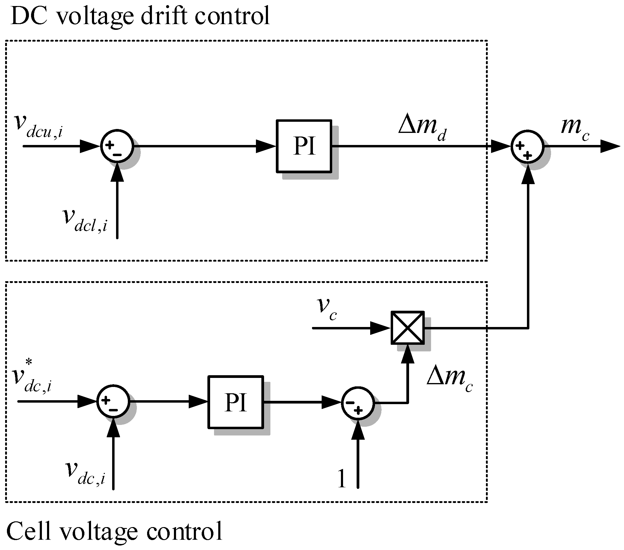
3.3. Voltage Balancing Control and Power Balance Scheme

As mentioned, correct power distribution between both cells and a control strategy to avoid voltage unbalancing in the DC-link capacitors is required to provide full operation in the 5L-CTNPC. The compensation block shown in Figure 6 is separated into two parts. The first one is the DC-link balancing control between cells, whose purpose is to regulate the power mismatch by increasing or decreasing the general modulation index amplitude, also referred to as the normalized inverter voltage v c delivered from the current controller. In this control loop, the DC voltage error is regulated by using a PI controller and then the voltage compensator Δ m c is multiplied by the normalized inverter voltage reference v c [29]. Therefore, the cell with higher power will increase its modulation amplitude, as the cell with lower power reduces its modulation amplitude. The second part of the control loop is given by the voltage balancing between the internal capacitors in the DC-link, where the voltage error is controlled using another PI controller. The output signal of this compensator Δ m d is added to the modulation index provided by the cell voltage control by moving in the vertical axis the modulation index for capacitor balancing purposes. Both PI controllers have been designed by a pole placement strategy, using a bandwidth of 5 Hz. This dynamic has been imposed to avoid fast disturbances into the modulation signal. Note that the proposed balancing control scheme does not need extra measurements, since they are previously accessible from the outer control stage.

4. Results

Simulation and experimental results of the proposed configuration are presented in this section. The simulation analysis has been performed through MatLab/Simulink for control purposes, while PLECS were used for modelling the modulation stage, power converter, grid voltage and PV strings. The analysis was completed by using the same scenarios of the experimental set-up just to improve the concept verification. The key simulation and experimental parameters are identified in Table 2. It is important to highlight that simulation parameters have been selected according to the reduced power experimental prototype.

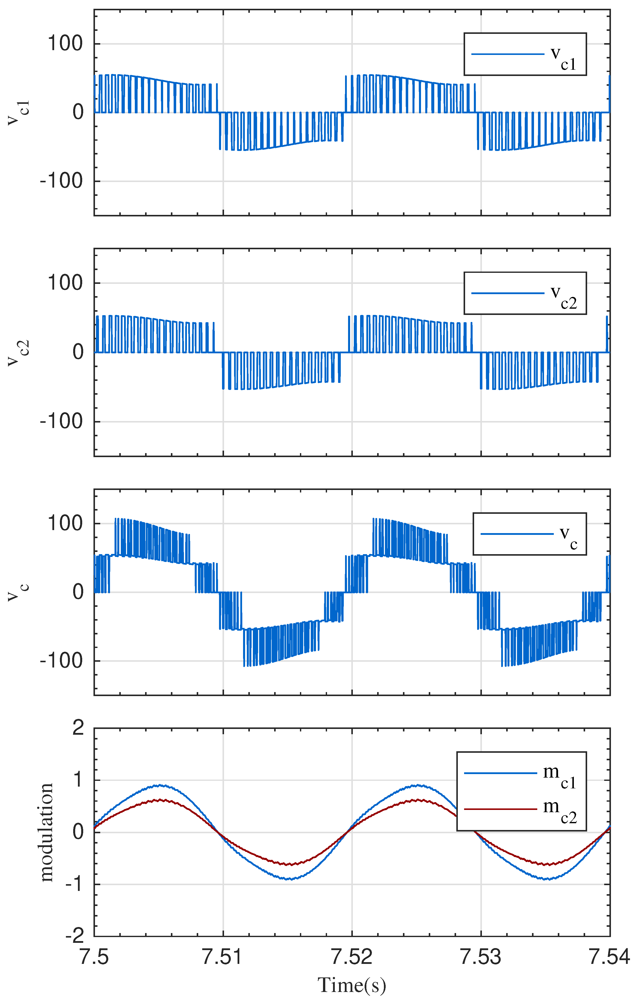
4.1. Simulation Results

The first simulation result presented the injected grid current i s with reference i s * and both capacitor voltages for each power cell under steady-state operation. In Figure 7, it is possible to appreciate the good regulation and synchronization in respect to the grid voltage v s performed by the grid current control and the synchronization control loop. Furthermore, in Figure 8, the voltage balancing control is demonstrated, where the upper v d c u , k and lower v d c l , k voltage capacitors for each k-th power cell are well balanced.
The second simulation results present a dynamic operation under two different scenarios. An irradiation step from 1 kW/m 2 to 0.8 kW/m 2 was applied to the lower cell, maintaining 1 kW/m 2 of irradiation in the PV string connected to the upper cell. After the irradiation step took place, a temperature step changes was performed from 25 C to 18 C to the upper cell, generating an increase in the power. The irradiation and temperature changes were introduced in a simplified PV model provided by PLECS. Figure 9 shows the dynamic operation of the DC-link voltage v d c k and the power at DC-side P c k = v d c k · i p v k for each k-th cell. It is possible to appreciate how the irradiation step at t = 3.5 s only affected to the lower module, producing a voltage perturbation and a power reduction in P c 2 . Since the reference voltage is provided by the P&O algorithm, the stepped voltage was required to maintain the maximum power operation. In the second scenario, the temperature decreased at t = 8 s and the DC voltage as well as the power in the upper module increased. The three-level voltage v c k of each converter cell, and the overall five-level voltage v c are depicted in Figure 10 under unbalance operation. Additionally, it is possible to appreciate how the power reduction in the lower arm affects the modulation indexes m c k , creating signals with different magnitudes.

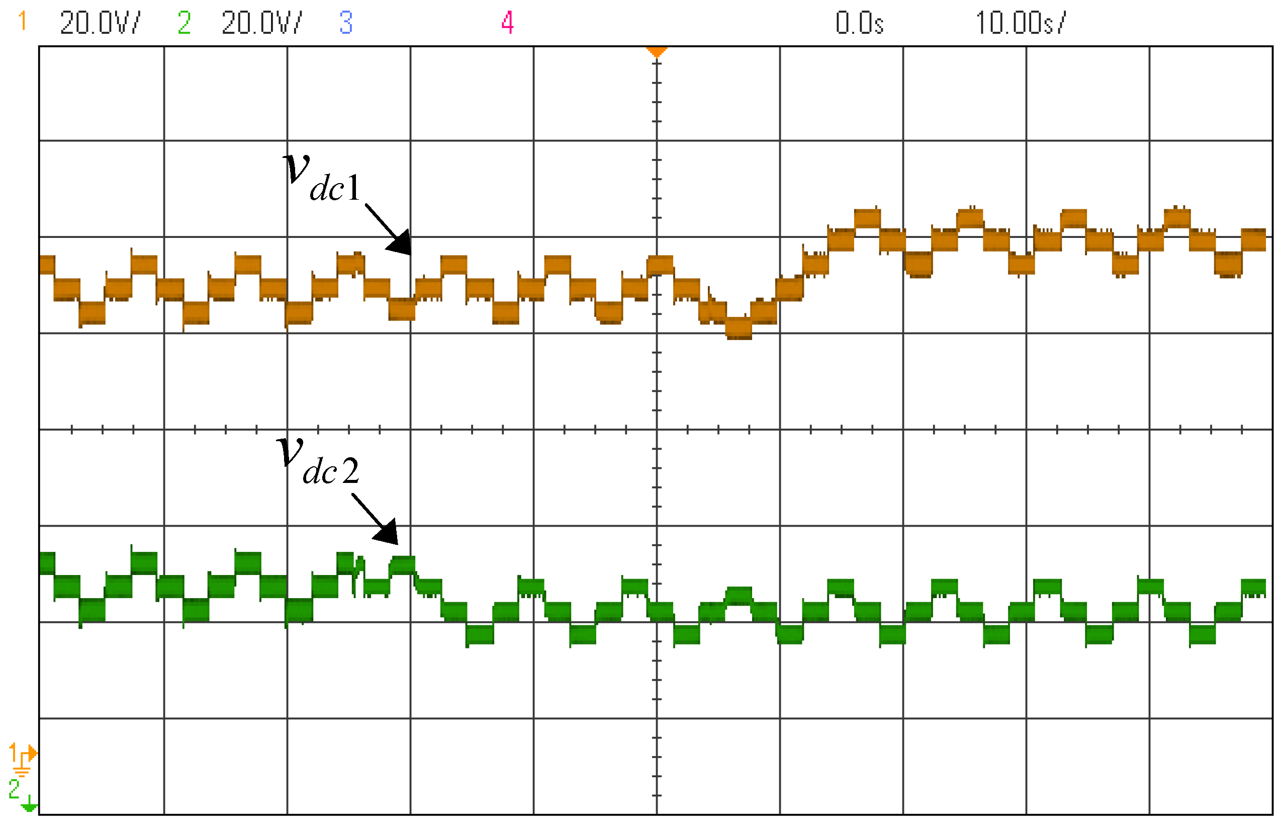
4.2. Experimental Results

The experimental PV system comprises of two 3L-TNPC power cells without isolation and were fed directly by one PV string. Each string was composed by two PV modules emulated with the Agilent E4360 solar array simulator, which enabled a total control of the temperature and irradiation parameters. Each simulator has two output channels connected in series to emulate the PV string generator. The parameters such as maximum power P m , current at maximum power i m p , short-circuit current i s c , voltage at maximum power v m p and open-circuit voltage v o c are listed in Table 2. The simplified layout of the experimental small-scale setup is depicted in Figure 11. The control algorithm is fully programmed in C code by using a dSPACE 1103 digital control platform running at 15 μ s. The modulation stage and dead-time generation is implemented by using a FPGA Spartan3. To experimentally validate the proposed control scheme, three different operation points are evaluated. A steady-state operation, and two dynamic operation under an irradiation and a temperature step.
The first experimental results shown in Figure 12 and Figure 13 are analyzed during steady-state operation. The grid-side variables i.e., grid current and voltage waveforms are presented in Figure 12, where the unitary power factor operation is achieved. Furthermore, Figure 13 captures the output voltage of each cell and the total voltage composed by a five-level waveform. Similar to the simulation results, the steady-state performance of the capacitor voltage balancing in Figure 14 is included.
The second set of experimental results during dynamic operation is shown in Figure 15 and Figure 16. Firstly, an irradiation step from 1 kW/m 2 to 0.8 kW/m 2 was applied to the second PV cell (lower cell operating at reduced power), while the first array irradiation level was retained. After this irradiance step variation, a temperature step change was tested from 25 C to 18 C and applied to the first PV cell (upper cell operating at increased power). Under the above conditions, the input voltages generate a three-level waveform signal due to the use of the conventional P&O MPPT method. Note that under both scenarios, the coupling effects from one cell to each other is fully avoided, ensuring a decoupled operation between power cells.

4.3. Brief Comparison with Other Five-Level T-type Converters

A comprehensive comparison between three different five-level T-type converters have been presented in Table 3. The studied topologies are the proposed 5L-CTNPC, the hybrid version 5L-HTNPC and the conventional 5L-TNPC. Each topology presents the same features of the one described in simulation and experimental results. To evaluate the power efficiency of each converter, switching and conduction losses is required in respect to the power operation point for each cell. Semiconductor device losses are included with a thermal model library developed in PLECS, based on the manufacturer datasheet [30]. The resulting efficiency evaluation is depicted in Figure 17, where the obtained efficiency of the proposed configuration 5L-CTNPC is equal to the conventional 5L-TNPC. Due to the fact that there is a reduced number of switches at the second parallel leg in the 5L-HTNPC a slightly higher efficiency was achieved. This analysis is corroborated by counting the number of semiconductor devices used for each evaluated topology, which is summarized in Table 3.
The symmetrical topology configuration and the multiple MPPT possibilities are the main advantages of the studied topology in respect to the rest power converters. Finally, in Figure 18 the current spectrum for each evaluated converter topology is computed. The current THD obtained with the proposed topology is similar to the conventional 5L-TNPC power topology, while the worst value (over 4.9%) was reached in the 5L-HTNPC configuration. In fact, the apparent switching frequency of this topology was equal to the carrier frequency, while in the proposed 5L-CTNPC and 5L-TNPC the apparent switching frequency was twice the switching frequency.

5. Conclusions

In this work a grid-tied PV system configuration based on a series connection of three-level T-type inverter cells was described and validated. The proposed power topology merged the benefits of multistring configurations with more than one independent MPPT capability and the benefits of cascade H-bridge converters, generating a five-level output voltage waveform in the AC terminals. The proposed topology, modulation and control scheme were validated experimentally in a reduced scale power prototype with a straightforward implementation. Additionally, the proposed control strategy was evaluated under steady-state and unbalanced power conditions, ensuring a decoupled operation between both power cells. Finally, a brief comparison for key merit figures was included, where the main advantages of the proposed topology among other T configurations were highlighted, giving rise to the possibility of enhancing the power extraction from the PV side due to the multi-string configuration.

Author Contributions

C.V. conceived, designed and performed the experimental evaluations; S.K. provided insight on the power topology and conceptual solution, and was responsible of supervision throughout the work; C.A.R. wrote the manuscript and was part of the development team of the experimental test-bench, M.A.P. was responsible for the guidance during the prototype design stage, T.M. and M.M. provided relevant key theoretical and technical suggestions.

Funding

The authors gratefully acknowledge the financial support provided by CONICYT REDES 170217, AC3E (CONICYT/BASAL/FB0008), SERC Chile (CONICYT/FONDAP/15110019), CONICYT + PAI CONVOCATORIA NACIONAL SUBVENCION A INSTALACION EN LA ACADEMIA CONVOCATORIA 2018 + PAI77180032.

Conflicts of Interest

The authors declare no conflict of interest.

Abbreviations

The following abbreviations are used in this manuscript:
ACAlternating Current
DCDirect Current
PVPhotovoltaic
NPCNeutral Point Clamped
MLIMulti Level Inverter
THDTotal Harmonic Distortion
MVMedium-Voltage
3L-NPCThree-Level Neutral Point Clamped
3L-TNPCThree-Level T-type Neutral Point Clamped
3L-NPPThree-Level Neutral Point Piloted
5L-TNPCFive-Level T-type Neutral Point Clamped
5L-HTNPCFive-Level Hybrid T-type Neutral Point Clamped
CHBCascade H-Bridge
9L-TNPCNine-Level T-type Neutral Point Clamped
5L-CTNPCFive-Level Cascade T-type Neutral Point Clamped
IGBTIsolated Gate Bipolar Transistor
MOSFETMetal Oxide Semiconductor Field Effect Transistor
MPPTMaximum Power Point Tracking
PIDPotential-Induced Degradation
PWMPulse Width Modulation
LS-PWMLevel-Shifted Pulse Width Modulation
PS-PWMPhase-Shifted Pulse Width Modulation
SVMSpace Vector Modulation
PMRProportional Multiresonant
P&OPerturb and Observe
PIProportional-Integral
SOGISecond Order Generalized Integrator
SRF-PLLSynchronous Reference Frame Phase Lock Loop

Nomenclature

The following variable nomenclature is used along figures and tables of this manuscript:
v s Grid voltage
i s Grid current
L s Filter inductor
R s Filter resistor for modelling purposes
v c Total converter voltage
v c k Converter voltage per cell
C d c Capacitance per cell
S k 1 , S k 2 Switching signals per cell
v d c u , k , v d c l , k Upper and lower capacitor voltages per cell
v d c , k DC-link voltage per cell
v d c k * DC-link voltage reference per cell
v p v , k PV voltage per cell
i p v , k PV current per cell
m c k Modulation reference signal per cell
v c r 1 , v c r 2 Carrier signals
v c * Per-unit converter voltage reference
e k Energy error per cell
e T Total error energy
i ^ s Reference current magnitude
ω s Angular grid frequency
θ Grid angle
f s Grid frequency
G f Notch filter
Δ v p v MPPT voltage step
T k MPPT time step
i s * Current reference
C i ( s ) Current controller
k p Proportional gain of the PMR controller
k i h Integral gain of the PMR controller for each h-th frequency component
hGrid harmonic
v L Inductor voltage
v L * Inductor voltage reference
f c r Carrier frequency
T s Sampling period
BW v d c DC-link control bandwidth
BW i s Current control bandwidth
BW d v Balancing control bandwidth
P m p Maximum power
v m p Voltage at maximum power
v o c Open-circuit voltage
i m p Current at maximum power
i s c Short-circuit current
Δ m d Voltage drift modulation component
Δ m c Cell voltage control
P c k Power per cell

References

  1. Kouro, S.; Leon, J.I.; Vinnikov, D.; Franquelo, L.G. Grid-Connected Photovoltaic Systems: An Overview of Recent Research and Emerging PV Converter Technology. IEEE Ind. Electron. Mag. 2015, 9, 47–61. [Google Scholar] [CrossRef]
  2. Jedtberg, H.; Pigazo, A.; Liserre, M.; Buticchi, G. Analysis of the Robustness of Transformerless PV Inverter Topologies to the Choice of Power Devices. IEEE Trans. Power Electron. 2017, 32, 5248–5257. [Google Scholar] [CrossRef] [Green Version]
  3. Kouro, S.; Malinowski, M.; Gopakumar, K.; Pou, J.; Franquelo, L.G.; Wu, B.; Rodriguez, J.; Perez, M.A.; Leon, J.I. Recent Advances and Industrial Applications of Multilevel Converters. IEEE Trans. Ind. Electron. 2010, 57, 2553–2580. [Google Scholar] [CrossRef]
  4. Muñoz-Cruzado-Alba, J.; Rojas, C.A.; Kouro, S.; Díez, E.G. Power production losses study by frequency regulation in weak-grid-connected utility-scale photovoltaic plants. Energies 2016, 9, 317. [Google Scholar] [CrossRef]
  5. Wang, Y.; Shi, W.W.; Xie, N.; Wang, C.M. Diode-Free T-Type Three-Level Neutral-Point-Clamped Inverter for Low-Voltage Renewable Energy System. IEEE Trans. Ind. Electron. 2014, 61, 6168–6174. [Google Scholar] [CrossRef]
  6. Shi, Y.; Wang, L.; Xie, R.; Shi, Y.; Li, H. A 60-kW 3-kW/kg Five-Level T-Type SiC PV Inverter With 99.2% Peak Efficiency. IEEE Trans. Ind. Electron. 2017, 64, 9144–9154. [Google Scholar] [CrossRef]
  7. Schweizer, M.; Kolar, J.W. Design and Implementation of a Highly Efficient Three-Level T-Type Converter for Low-Voltage Applications. IEEE Trans. Power Electron. 2013, 28, 899–907. [Google Scholar] [CrossRef]
  8. Semikron: 3L NPC and TNPC Topology. 2015. Available online: https://www.semikron.com/zh/service-support/downloads/detail/semikron-application-note-3l-npc-tnpc-topology-en-2015-10-12-rev-05.html (accessed on 1 March 2019).
  9. Infineon: 3-Level configurations. 2016. Available online: https://www.infineon.com/dgdl/Infineon-3_ Level_Inverter-PB-v08_00-EN.pdf?fileId=db3a30432a14dd54012a31d664d90273 (accessed on 1 March 2019).
  10. OnSemiconductor: Q0PACK Modules. 2018. Available online: https://www.onsemi.com/pub/Collateral/NXH80T120L2Q0S2G-D.PDF (accessed on 1 March 2018).
  11. Joetten, R.; Gekeler, M.; EIBEL, J. AC drive with three level voltage source inverter and high dynamic performance micropocessor control. In Proceedings of the First European Conference on Power Electronics and Applications, Brussels, Belgium, September 1985; p. 6. [Google Scholar]
  12. Salem, A.; Abido, M.A. T-Type Multilevel Converter Topologies: A Comprehensive Review. Arab. J. Sci. Eng. 2018, 44, 1713–1735. [Google Scholar] [CrossRef]
  13. Xue, Y.; Manjrekar, M. A new class of single-phase multilevel inverters. In Proceedings of the 2nd International Symposium on Power Electronics for Distributed Generation Systems, Hefei, China, 16–18 June 2010; pp. 565–571. [Google Scholar]
  14. Almeida Cacau, R.; Torrico-Bascope, R.P.; Neto, J.A.F.; Torrico-Bascope, G.V. Five-Level T-Type Inverter Based on Multistate Switching Cell. IEEE Trans. Ind. Appl. 2014, 50, 3857–3866. [Google Scholar] [CrossRef]
  15. Aly, M.; Ahmed, E.M.; Shoyama, M. Modulation Method for Improving Reliability of Multilevel T-type Inverter in PV Systems. IEEE J. Emerg. Sel. Top. Power Electron. 2019, 1. [Google Scholar] [CrossRef]
  16. Valderrama, G.E.; Guzman, G.V.; Pool-Mazun, E.I.; Martinez-Rodriguez, P.R.; Lopez-Sanchez, M.J.; Zuniga, J.M.S. A Single-Phase Asymmetrical T-Type Five-Level Transformerless PV Inverter. IEEE J. Emerg. Sel. Top. Power Electron. 2018, 6, 140–150. [Google Scholar] [CrossRef]
  17. Limones-Pozos, C.A.; Martinez-Rodriguez, P.R.; Sosa, J.M.; Vazquez, G.; Izaguirre-Vera, A. Design and analysis of a single-phase transformerless multilevel 7L-TT-HB cascade inverter for renewable energy applications. In Proceedings of the 2018 IEEE International Autumn Meeting on Power, Electronics and Computing (ROPEC), Ixtapa, Mexico, 14–16 November 2018; pp. 1–6. [Google Scholar] [CrossRef]
  18. Chang, W.-N.; Liao, C.-H. Design and Implementation of a STATCOM Based on a Multilevel FHB Converter with Delta-Connected Configuration for Unbalanced Load Compensation. Energies 2017, 10, 921. [Google Scholar] [CrossRef]
  19. Yoo, A. Multi-Ievel Medium-Voltage Inverter. 2015/EP2822164A2. 2015. Available online: https://patents.google.com/patent/EP2822164A2/en (accessed on 1 May 2018).
  20. Verdugo, C.; Kouro, S.; Perez, M.A.; Malinowski, M.; Meynard, T. Series-connected T-type Inverters for single-phase grid-connected Photovoltaic Energy System. In Proceedings of the 39th Annual Conference of the IEEE Industrial Electronics Society (IECON 2013), Vienna, Austria, 10–13 November 2013; pp. 7021–7027. [Google Scholar] [CrossRef]
  21. Mori, S.; Aketa, M.; Sakaguchi, T.; Asahara, H.; Nakamura, T.; Kimoto, T. Demonstration of 3 kV 4H-SiC reverse blocking MOSFET. In Proceedings of the 2016 28th International Symposium on Power Semiconductor Devices and ICs (ISPSD), Prague, Czech Republic, 12–16 June 2016; pp. 271–274. [Google Scholar] [CrossRef]
  22. Gurpinar, E.; Castellazzi, A. Single-Phase T-Type Inverter Performance Benchmark Using Si IGBTs, SiC MOSFETs, and GaN HEMTs. IEEE Trans. Power Electron. 2016, 31, 7148–7160. [Google Scholar] [CrossRef]
  23. Chub, A.; Vinnikov, D.; Blaabjerg, F.; Peng, F.Z. A Review of Galvanically Isolated Impedance-Source DC-DC Converters. IEEE Trans. Power Electron. 2016, 31, 2808–2828. [Google Scholar] [CrossRef]
  24. Dargahi, V.; Abarzadeh, M.; Corzine, K.A.; Enslin, J.H.; Sadigh, A.K.; Rodriguez, J.; Blaabjerg, F.; Maqsood, A. Fundamental Circuit Topology of Duo-Active-Neutral-Point-Clamped, Duo-Neutral-Point-Clamped, and Duo-Neutral-Point-Piloted Multilevel Converters. IEEE J. Emerg. Sel. Top. Power Electron. 2018, 1. [Google Scholar] [CrossRef]
  25. Serban, E.; Pondiche, C.; Ordonez, M. Modulation Effects on Power-Loss and Leakage Current in Three-Phase Solar Inverters. IEEE Trans. Energy Convers. 2019, 34, 339–350. [Google Scholar] [CrossRef]
  26. Leon, J.I.; Kouro, S.; Franquelo, L.G.; Rodriguez, J.; Wu, B. The Essential Role and the Continuous Evolution of Modulation Techniques for Voltage-Source Inverters in the Past, Present, and Future Power Electronics. IEEE Trans. Ind. Electron. 2016, 63, 2688–2701. [Google Scholar] [CrossRef]
  27. Lee, T.; Bu, H.; Cho, Y. Hybrid PWM Strategy for Power Efficiency Improvement of 5-Level TNPC Inverter and Current Distortion Compensation Method. Electronics 2019, 8, 76. [Google Scholar] [CrossRef]
  28. Teodorescu, R.; Liserre, M.; Rodriguez, P. Grid Converters for Photovoltaic and Wind Power Systems; John Wiley & Sons: Hoboken, NJ, USA, 2011. [Google Scholar]
  29. Kouro, S.; Wu, B.; Moya, A.; Villanueva, E.; Correa, P.; Rodriguez, J. Control of a cascaded H-bridge multilevel converter for grid connection of photovoltaic systems. In Proceedings of the 2009 35th Annual Conference of IEEE Industrial Electronics, Porto, Portugal, 3–5 November 2009; pp. 3976–3982. [Google Scholar] [CrossRef]
  30. IGBT Model IXXK100N60C3H1 Datasheet. 2015. Available online: https://hr.mouser.com/ProductDetail/IXYS/IXXK100N60C3H1/?qs=DTxAbJQb9nVqmCmAy76OGQ%3D%3D (accessed on 1 May 2018).
Figure 1. Proposed 5L-CTNPC power topology.
Energies 12 01743 g001
Figure 2. Proposed modulation scheme for 5L-CTNPC based on the hybrid LS-PWM and PS-PWM.
Energies 12 01743 g002
Figure 3. Straightforward implementation of hybrid LS-PWM and PS-PWM modulation for a 5L-CTNPC converter.
Energies 12 01743 g003
Figure 4. Single-phase voltage-oriented control strategy for the proposed 5L-CTNPC converter.
Energies 12 01743 g004
Figure 5. Stationary current control loop implemented with PMR controllers.
Energies 12 01743 g005
Figure 6. Implemented voltage balancing control strategy per 3L-TNPC cell.
Energies 12 01743 g006
Figure 7. Steady-state operation of the grid current PMR control.
Energies 12 01743 g007
Figure 8. Steady-state operation of capacitor voltages for each power cell.
Energies 12 01743 g008
Figure 9. Dynamic operation of DC-link and power on the DC-side under unbalanced power per string.
Energies 12 01743 g009
Figure 10. Steady-state converter output voltage performance under unbalanced power per string.
Energies 12 01743 g010
Figure 11. Simplified diagram of implemented experimental setup.
Energies 12 01743 g011
Figure 12. Steady-state experimental results at grid-side variables: Grid current and voltage waveforms.
Energies 12 01743 g012
Figure 13. Steady-state experimental results at converter-side variables: Output voltage for each cell and total output voltage.
Energies 12 01743 g013
Figure 14. Steady-state experimental results of capacitor voltage across each 3L-TNPC cell.
Energies 12 01743 g014
Figure 15. Experimental dynamic operation of DC-link voltage under unbalanced power per string due to solar irradiation and temperature changes.
Energies 12 01743 g015
Figure 16. Experimental dynamic operation of DC power under unbalanced power per string due to solar irradiation and temperature changes.
Energies 12 01743 g016
Figure 17. Efficiency comparison between 5L-CTNPC, 5L-HTNPC and 5L-TNPC inverter topologies respect to the power operation.
Energies 12 01743 g017
Figure 18. Grid current FFT comparison between 5L-CTNPC, 5L-HTNPC and 5L-TNPC inverter topologies.
Energies 12 01743 g018
Table 1. Switching states and output voltage in the AC terminals.
State S 11 S 12 S 21 S 22 v c
11111 v d c 1 / 2 + v d c 2 / 2
21101 v d c 1 / 2
30111 v d c 2 / 2
41100
500110
60101
70100 v d c 1 / 2
80001 v d c 2 / 2
90000 v d c 1 / 2 v d c 2 / 2
Table 2. Simulation and experimental parameters.
SymbolParameterSimulation ValueExperimental Value
Grid Parameters
v ^ s Peak grid voltage80 (V)80 (V)
f s Grid frequency50 (Hz)50 (Hz)
Converter Parameters
C d c DC-link capacitors1950 ( μ F)1950 ( μ F)
f c r Carrier frequency2000 (kHz)2083 (kHz)
L s Grid inductance5 (mH)5 (mH)
R s Grid resistance0.01 ( Ω )1 ( Ω )
Control Parameters
T s Sample period10 ( μ s)15 ( μ s)
BW v d c DC-link control bandwidth14 (Hz)14 (Hz)
BW i s Current control bandwidth270 (Hz)270 (Hz)
BW d v Balancing control bandwidth5 (Hz)5 (Hz)
MPPT Parameters
T k P&O period0.24 (s)2.1 (s)
Δ v p v P&O voltage step6 (V)6 (V)
PV String Parameters
P m p Maximum power106 (W)106 (W)
v m p Voltage at maximum power48.4 (V)48.4 (V)
v o c Open-circuit voltage65.0 (V)65.0 (V)
i m p Current at maximum power2.2 (A)2.2 (A)
i s c Short-circuit current2.6 (A)2.6 (A)
Table 3. Brief comparison between five-level T-type topologies.
Parameter5L-CTNPC5L-HTNPC5L-TNPC
DC-link voltage v d c v d c v d c
IGBT blocking voltage 4 × v d c , 4 × v d c / 2 4 × v d c , 2 × v d c / 2 4 × v d c , 4 × v d c / 2
IGBT switching freq.8 × 2 (kHz)4 × 2 (kHz), 2 × 50 (Hz)8 × 2 [kHz]
Apparent output voltage Ffreq.4 (kHz)2 (kHz)4 [kHz]
Grid current THD2.83%4.91%2.53%
Switching losses0.087%0.078%0.087%
Cond. losses1.467%1.409%1.469%
Converter efficiency98.43%98.51%98.44%
MPPT efficiency+++++++
Topology configureSymmetricalAsymmetricalSymmetrical
2 MPPT1 voltage control loop1 voltage control loop
AdvantagesHigh energy yieldGood power qualityHigh power quality
High power quality
Disadvantages2 voltage control loops1 MPPT only1 MPPT only
High cond. lossesDC-voltage offsetsHigh cond. losses

