Article

Modular Self-Balancing Battery Charger Concept for Cost-Effective Power-Assist Wheelchairs

1
Faculty of Power and Electrical Engineering, Riga Technical University, LV1048 Riga, Latvia
2
Department of Electrical Power Engineering and Mechatronics, Tallinn University of Technology, 19086 Tallinn, Estonia
3
Department of Industrial Electronics, National Technical University of Ukraine “Igor Sikorsky Kyiv Polytechnic Institute”, 03056 Kyiv, Ukraine
*
Author to whom correspondence should be addressed.
Energies 2019, 12(8), 1526; https://doi.org/10.3390/en12081526
Submission received: 28 February 2019 / Revised: 7 April 2019 / Accepted: 16 April 2019 / Published: 23 April 2019
(This article belongs to the Special Issue Power Electronic Systems for Efficient and Sustainable Energy Supply)

Abstract

:
The paper deals with a power charger capable of quick simultaneous charging of several unevenly discharged batteries. The charger is designed for use in conjunction with a recently developed power-assist wheelchair composed of two armrest modules associated with wheels—each with its own motor, driver and battery. Uneven discharge of the batteries is very possible in this application. Taking into account the charging power and energy comparable with the most powerful household electrical devices, the refreshing of these batteries and integration of the entire power supply chain into the household grid become a topical and challenging task. Solving of this task requires a special charger that has several channels and can unevenly apply charging power to these channels. At the same time, the charger must not generate current harmonics or reactive power, must operate with good efficiency and satisfy size constraints. In the given research, a configuration of several interleaved isolated single-ended primary-inductor converters is studied. The synthesized mathematical model of the proposed charger provides data about its static and dynamic characteristics while its experimental investigation focuses on operation details (power losses, control features etc.). The obtained results prove that the proposed concept complies with the above-mentioned requirements and can be applied in the discussed application.

1. Introduction

Sustainable and efficient energy supply is equally important to larger and smaller objects: Energy consumers or energy prosumers. On the other hand, the influence of energy supply in many cases is not purely technical or economical, but also social. In some cases, this social influence is even more important than its technical benefits. Below, an example of such an application of significant social importance, an energy supply system for a power-assist wheelchair, is discussed. At the same time, nowadays, advanced power electronic converters are widely used as functional tools to form a sustainable and efficient energy supply. In the considered application, an extended version of power single-ended primary-inductor converter (SEPIC) topology in conjunction with wise power flow control and optimization provides quick and balanced charging of the wheelchair batteries.
According to a report of the World Health Organization (WHO) one third of a billion elderly and disabled persons have mobility problems [1]. Many of these persons are highly motivated to improve their mobility combining electrical powering of their wheelchairs with muscle powering thus ensuring their own maximal feasible participation in daily life (i.e., assuming the use of power-assist wheelchairs). At the same time, the power-assist and electrically-powered wheelchairs are still expensive devices that reduces their availability to their potential users. Therefore, the question of cost effectiveness is one of the most important when talking about the development of power-assist wheelchairs. This research outlines the problems and challenges of the development of an energy supply of electrical subsystem for cost-effective power-assist wheelchairs.
The scientific and technical novelties of this work follow from the particular wheelchair application. The paper explains which problems are found in the application, as well as how these problems can be solved with the help of power electronic converters. Firstly, the wheelchair users, types, functions and problems are identified. Secondly, a wheelchair design solving the identified problems is suggested and described. Thirdly, the role of power electronics, particularly, of an electric charger in the wheelchair set is revealed. Then the parameters of the charger are defined and the requirements are brought forward. Finally, the power electronic converter operating as a specific battery charger is proposed and verified experimentally.

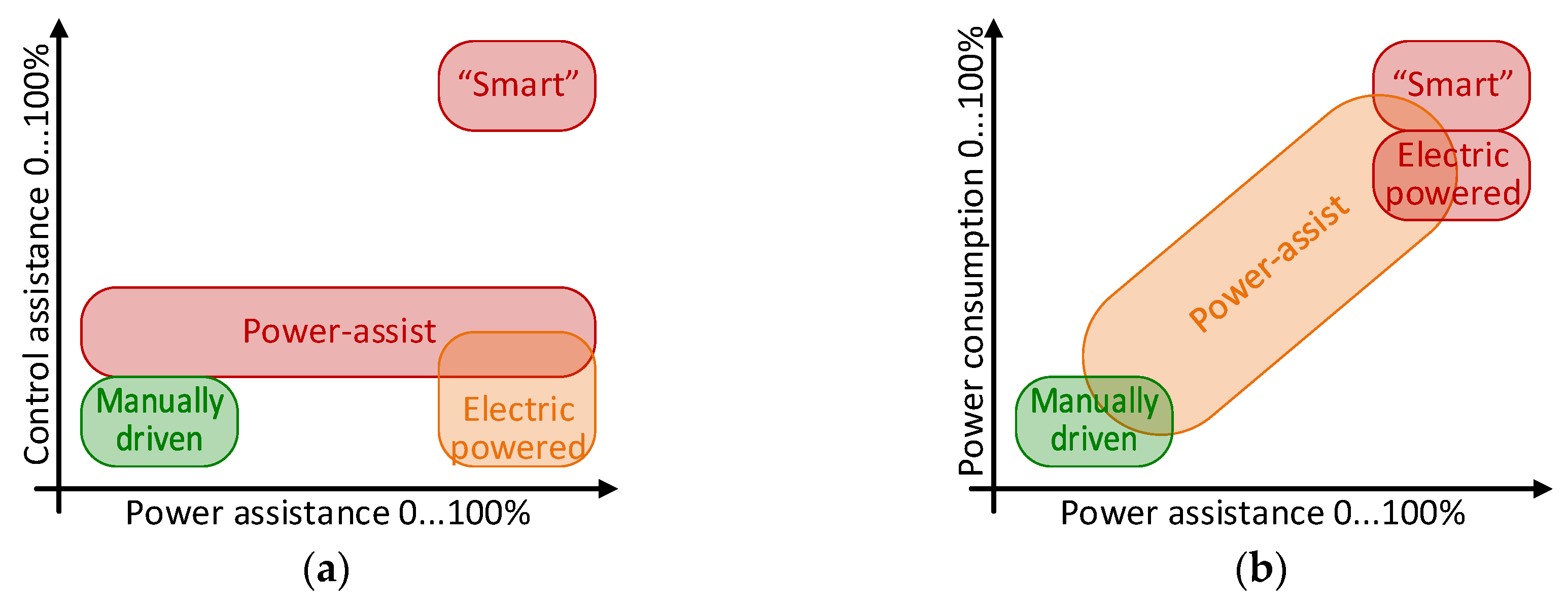
1.1. Wheelchairs Users and Types

The following categories of wheelchair users can be emphasized: (group 1) persons with permanent or progressive disability caused by an illness or injury, (group 2) persons with disability related to their ageing and (group 3) persons with temporary (reducing) disability during rehabilitation process after some orthopedic or other similar problem. Wheelchairs that are developed for persons with disabilities caused by an illness or injury are different compared with disabilities related to ageing. While seniors require powered wheelchairs with quite a typical and predictable level of assistance, the wheelchairs for persons with disability due to an injury or illnesses often require a more specific design with various movement reference defining tools, control and drive schemes. This design depends, first of the all, on the particular kind of disability of such wheelchair users. A significant number of users (subgroup 1a) with monoplegia (dysfunction of one limb) and paraplegia (dysfunction of two limbs) are capable of continuous muscle powering of their wheelchairs. Other wheelchair users (subgroup 1b) can do it only temporarily but can continuously use direct set-point defining tools, for example, joysticks. Finally, there are such users, typically with tetraplegia, who neither can continuously power the wheelchairs nor control them directly (subgroup 1c). As it can be seen, the evaluated external power demand of the users of different categories may also be very different. Moreover, this demand may vary over the time in the case of progressive disability and successful rehabilitation.
Actual demand in external power is influenced by one more factor, namely, wish and motivation to use as much own muscle power as possible. The analysis of the world wide [1], US [2] and European [3] reports on disability show that there exists significant numbers of highly motivated persons amongst all categories of wheelchair users. It means that, although the parameters of a power-assist wheelchair has to be calculated for the highest intensity of assistance and for the heaviest user, they can be reduced for others. At the same time, the cost effectiveness requires that the same design of the wheelchair be used with a wide range of power of electrical subsystem, thus providing the reduction of price for versions with reduced power.
Recommendations on the wheelchair selection [4] typically mention four groups of the wheelchairs available on the market as shown in Figure 1. The first group include manually driven wheelchairs—lightweight, expandable/easily transportable and low-cost vehicles. These wheelchairs, however, are suitable only for the users of groups (1a) and (3)—those whose disability is not very significant. The next group is formed of electric-powered wheelchairs [5], which are in fact small sized electric cars equipped with one or two electrical propulsion drives, a joystick for movement reference and even lighting devices. They are suitable for all categories of the potential wheelchair users. However, the drawback of these wheelchairs (significant weight and size, absence of expandability, difficult transportability and, particularly, high price) significantly limits their use. Newer wheelchairs, known as power-assist [6], are a kind of electric-powered wheelchairs—they form the third group. Typically, they are equipped with the motored wheels, capable of providing adjustable extra torque, as well as with a torque-sensing–amplifying system to more flexibly define the movement reference. The wheelchairs of this group are not as heavy as the electric-powered wheelchairs, they are more portable, but may be even more expensive [7]. The main advantage of the power-assist wheelchairs is their capability of combining the electrically-produced and manually-provided torque. Finally, one more kind of electric-powered wheelchairs are regarded as smart wheelchairs. Their main feature is a decision-making system that turn these wheelchairs into autonomous robotic vehicles.
Even a brief analysis of the above-described groups of the wheelchairs shows that their common feature is a rigid (fixed) configuration. While the power adaptation at high cost is more or less implemented in the power-assist wheelchairs, control adaptation in usually not considered. For this reason, currently available wheelchairs are not easy adoptable for needs of a particular user. This is very important in certain cases, for example, in the case of progressive and reducing disability. This makes them more expensive and, therefore, less available than they could be in the case of careful fit to particular needs. Trying to fix this problem and fulfill the corresponding societal request in an inexpensive smart device for disabled people the authors of this work proposed a concept of a cost-effective adoptable and hardware-reconfigurable power-assist wheelchair.

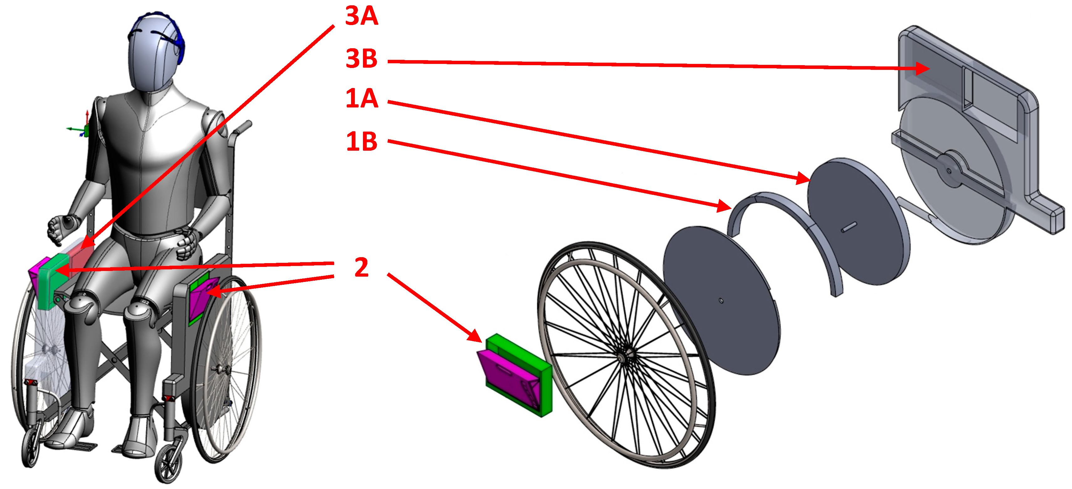
1.2. Concept of a Cost-Effective Adoptable Power-Assist Wheelchair

The main idea of the proposed concept is integration of the power electrical equipment (scalable electrical motor-generator, its electronic driver, battery, its balancing-management system and charger), control and measurement hardware (sensor networks, motion reference devices, machine–human feedbacks and decision-making unit), as well as information technologies in a single versatile and expandable hardware platform. The concept has been briefly described in [8], its control subsystem—in [9], electrical subsystem—in [10], but more details about its scalable motor-generator—in [11]. Below, this concept is described briefly in order to introduce the electrical/mechanical requirements of the charger.
As presented in Figure 2, the wheelchair consists of two armrest modules (left and right) connected by a flexible seat and backrest, which makes the design itself flexible and compatible with the existing technologies of wheelchair manufacturing (that reduce the price). In the same time, this flexibility does not allow storage of the charger under the seat or behind the backrest. Therefore, one of the armrest modules must have also a compartment for the charger, while the other may use the corresponding room to locate the decision-making unit. Each of the armrest modules is also equipped with its own electrical drive and battery. The control elements, sensors and machine–to–human feedbacks are distributed between the armrest modules and located on them in proper places. In cruise configuration (on the move), the modules have no power electrical link between them—only communications between them are available. It is assumed that in still configuration (when the wheelchair is deployed but does not move) the charger is connected to the supply network and batteries without its physical removal from the compartment. This defines the dimensions of the charger (equal to a compartment 200 mm × 130 mm × 40 mm) and applies cooling and safety limitations. At the same time, in the idle configuration (when folded) the charger can be located outside and must be ready for easy (one click) placement of the batteries that defines specific connection options for the batteries and charger.

1.3. Electrical Parameters of the Charger

The electrical parameters of the charger follow from those of the utilized batteries. General considerations on battery selection have been stated in [9], while more detailed analysis of battery configuration in the context of energy efficiency—in [12]. Below these considerations are repeated briefly.
Analysis of battery technologies lead to the choice of Li-ion and lithium iron phosphate technology for the battery pack. Additionally, in the case of a laboratory prototype, the use of popular size type 18650 seems reasonable, because it allows utilization of a variety of battery types and combinations.
The choice of the battery voltage is determined by two principles: (1) Higher voltage leads to lower power losses in the electrical equipment; (2) safety considerations limit the rated voltage of the battery at the level of 24 V. Taking into account that the rated voltage of one cell is 3.6 V (that corresponds to minimal voltage of 2.5 V and maximal of 4 V), the required number of cells in series is 7.
The calculation of parallel branches on the battery is more complicated—it requires calculation of power of the wheelchair and battery capacity. They can be calculated based on the basic wheelchair operation parameters (cruise speed and operation time and range) defined in the worldwide [13], European [14] and national [15] standards, as well as taking into account reasonable mass of the wheelchair and its user.
The cruise power can be defined as a product
P t = F t × v
of cruise speed v and rolling resistance Ft, where the last parameter can be found as
| F t | / | N | = f / R   or   F t = N f / R
assuming N is the force vertically affecting the mass (gravitation), R—radius of the wheel and f—coefficient of rolling resistance, which depends on the materials of the surface and wheel. Taking into account the definition of gravitation force mg, the number of wheels Nw, as well as assuming that the mass of the wheelchair is m Equation (2) can be transformed to
F t = f R m g N w
Finally, taking into account the operation time, maximal speed and distribution between the maximal and cruise speed, as well as the efficiency of battery charge/discharge ηB produces the following formula for battery capacity in [Wh]:
C B = ( F t v 0.7 + F t v max 0.3 ) T η B
Applying the parameters from Table 1 in Equations (1)–(4), taking into account that there are two armrest modules and two batteries, as well as considering service functions it is possible to define the structure of the battery as 7S4P and bring forward the following list of requirements to the charger:
  • Charger shall be able to simultaneously charge two battery packs.
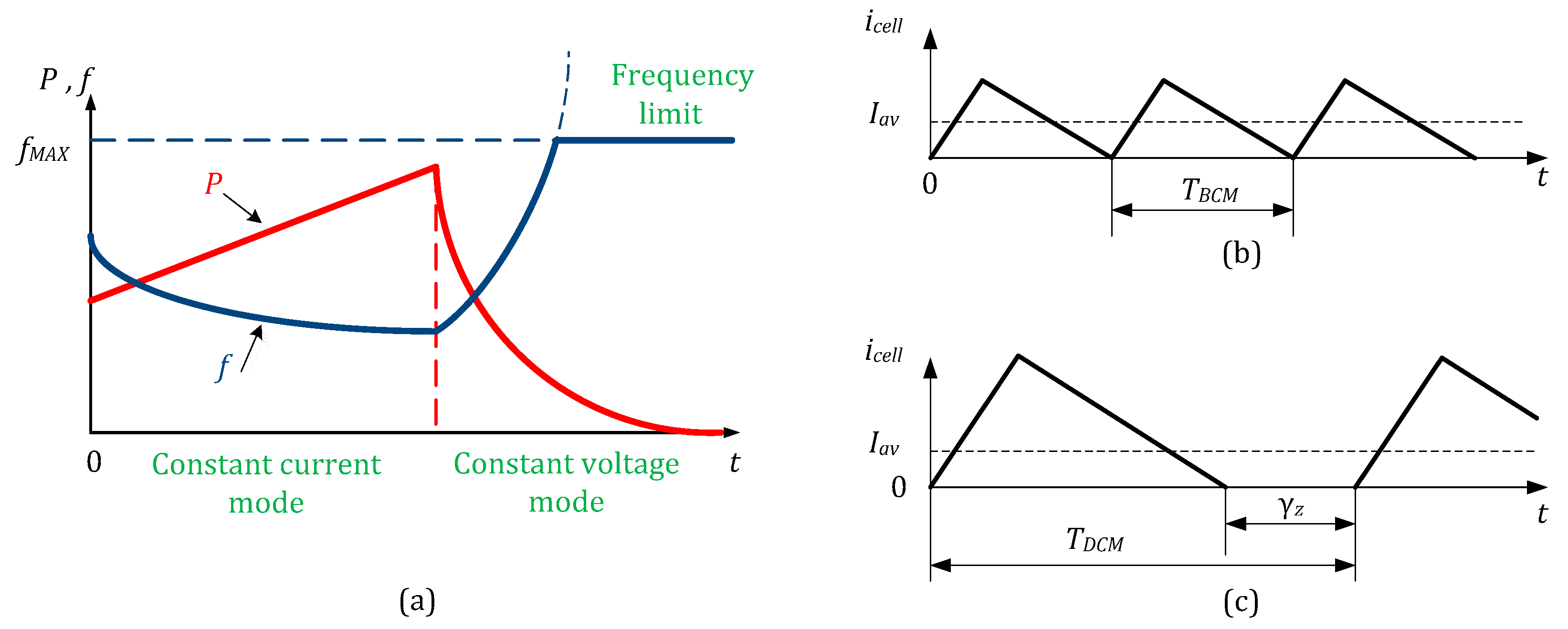
  • Battery shall be charged using Constant Current – Constant Voltage (CC–CV) charging mode.
  • During CC charging, the charger shall be able to provide at least 12 A current for a single battery pack.
  • During CV charging, the charger shall be able to charge battery pack to 29.4 V (or 7 Li-Ion cells with rated voltage 4.2V each).
  • Maximal charging power is 400 W per channel.
  • Charger shall stop charging once the charging current drops below 10% of the initially set current value.
  • Charger shall be able to start charging if the battery voltage is below 14 V.
  • Charger shall be able to communicate with the battery pack.
  • Battery pack shall provide information about charging current to the charger.
  • Battery pack shall be able to stop charging via communication.
  • Charger shall be designed to be able to be installed inside wheelchair’s side box.
  • Charger shall be designed in such a manner that the user shall be able to easily remove the charger from the wheelchair.
  • The charger shall be designed to provide on-board and off-board charging.
  • For on-board charging, there shall be a dedicated port to charge one battery pack that is in the same side box, while another port shall be used to connect a cable to the other side box where the other battery is located.
  • For off-board charging, there shall be two special ports on the charger. These special ports shall be used to plug in both batteries.
  • Charger shall have a standard cable to connect to an electrical grid.
  • Charger shall conform to relevant EU directives/regulations and Electromagnetic Compatibility (EMC) requirements, in particular, the alternating supply voltage (AC) is 250 V ±15%.
  • The shape of the charger shall be a rectangular prism. The main limiting dimension is height—max 40 mm. Charger shall lay flat when removed from the side box.

2. Topology and Design of the Charger

2.1. Analysis Power Factor Correction (PFC) Topologies and Choice of Topology for Charger

Development of a single channel charger with direct voltage (DC) supply is generally not a complicated task. It can be constructed based on a classical DC chopper or on a more sophisticated schematic like Ćuk, SEPIC or ZETA converters. However, it makes sense only in the context of DC grids. Then, safety requirements can be achieved with the help of a high-frequency transformer while separate battery blocks can be charged through their own module [16,17]. However, due to the dominance of AC supply networks, this approach is only a limited practical application possibility. The complete AC-supplied system requires also a power factor correction (PFC) stage to improve the quality of the current taken from the grid. At the same time, the presence of PFC does not allow the use of individual chargers for each battery, which would be too expensive. For this reason, the use of two-stage AC/DC converters is now often considered in the variety of battery interfacing applications [18]. These typically feature a power factor pre-regulator (PFP) stage that is followed by an isolated DC/DC stage [19,20], where each stage can achieve high maximum efficiencies.
In the given application, there are restrictions on the final height of the converter (about 35 mm) and the area available for magnetic components. This promotes the use of an interleaved structure and to realize a converter with several parallel-connected cells that incorporate components with smaller height and physical size. A multi-channel converter structure is also advantageous, for example, in the case of one-sided paraplegia of the wheelchair user one of two drive modules is more loaded and its batteries may discharge much quicker. In such a case, to achieve the full charge of the batteries simultaneously, one of the batteries must be charged more intensively.
The mentioned requirements can be realized separately on the basis of various converter topologies. For instance, the two-cell charger, in a general case, consists of a rectifier, a boost converter as PFC, DC-link capacitor, two isolated step-down converters and a charge balancing circuit as shown in Figure 3a. At the same time, such a system has a high number of components, which perform only one function. This may lead to large dimensions of the charger, not enough efficiency at some operating points, as well as higher cost [20].
Another approach involves the application of converters that satisfy the application requirements with a reduced number of stages. To achieve this, a variety of isolated PFC converters have been proposed: Combining a transistor bridge, push-pool and buck stages [21]; combining a transistor bridge and auxiliary fly-back converter [22]; based on a three-level topology [23]; based on isolated boost [24], fly-back [25], SEPIC and Ćuk [26,27], as well as based on a current-source converter [28]. For the current case study, it is beneficial to use isolated converters with a low component count, that allow for correcting the input current shape without a DC-link capacitor and preferably provide a natural charge balancing between batteries. Therefore, among the existing solutions, the PFC converters with the input inductor for easy input current shaping (boost, Ćuk and SEPIC) are more attractive. The isolated boost converter is not ideally suited, as it has high voltage stress on power devices or high input current distortion, dependent on the operation mode [29]. Isolated Ćuk converters possesses additional resonance, caused by magnetizing inductance of the transformer, that may form a major problem [30]. Unlike the other two converters, in SEPIС, the inductor can be replaced by a transformer without a significant increase in its dimensions [31]. Reference [32] proposes to use interleaved SEPIC topology to decrease switching power losses with high quality input current. Such a configuration allows a significantly reduced number of elements and volume of the charging system—Figure 3b.
Therefore, SEPIC operating in discontinuous conduction mode (DCM) [27,28,29,30,31] offers a number of advantages:
  • It operates as a voltage follower, meaning that the input current naturally follows the input voltage and a current control loop can be omitted;
  • galvanic isolation can be easily implemented and several isolated outputs provided;
  • the input current ripple is constant (assuming interleaving) and defined during the design stage;
  • can operate as step-up or step-down converter
  • Zero-Voltage Switching (ZVS) of the primary transistor and Zero-Current Switching (ZCS) of the output diode is provided.
The drawback can be attributed to voltage and rms (root-mean square) current stresses on semiconductors, which are higher than the ones of the comparable boost-type topology. Interleaving can be used to reduce the stresses, improve the input current ripple and increase the power level [32].

2.2. Proposed Charger Concept

A generalized non-isolated SEPIC topology is shown in Figure 4a. The substitution of inductor L2 with a transformer, as shown in Figure 4b, allows the implementation of almost all charger requirements simultaneously and is proposed as a basic charger cell [33].
The hypothesis of this research assumes that the charger, fulfilling the above listed requirements, may consist of several (N), parallel-connected SEPIC cells, supplied from the utility grid and connected to the same set of batteries. As many SEPIC cells as it is necessary can be applied to achieve good Total Harmonic Distortion (THD) and power factor (PF). Each of the SEPIC cells has the number of secondary windings, equal to the number of batteries, for example, two batteries require two windings in each SEPIC cell. In the example, corresponding to the considered wheelchair application, the SEPIC cells have two secondary windings, which are connected to two batteries. Potentially, in the case of an expandable sectional battery, the number of the parallel outputs may be increased to supply each battery section. In the configuration, presented in Figure 5, each battery is connected to the dedicated secondary winding of each SEPIC cells that links the entire charge current to the less charged battery with lower voltage.
Significant current ripples of each particular SEPIC cell, due to the interleaving, compensate each other so that the ripples of current in the utility grid are low, as shown in Figure 6. It means that the SEPIC cells operate with the same duty cycle γ and produce pulse sequences shifted by T/N, where T is switching period, N is a number of SEPIC cells.
The proposed solution may not be the most optimal one from the point of view of component count, simplicity of the circuit and efficiency. However, it must be taken into account that the contribution of the charger in the total price of the wheelchair set is 10%–12%. At the same time, there are some features influencing the price of the converter. Firstly, an inductor in the input allows omitting of the input filter or simplifying it. Secondly, various integrated SEPIC solutions potentially reduce the price of the charger keeping the proposed configuration. Finally, the proposed configuration of the charger helps to reduce the total price of the wheelchair set indirectly. Its multi-channel configuration is compatible with modularity of electrical and control subsystems of the wheelchair, that significantly reduces the price in the case of simplified configurations with light assistance level. The multi-channel configuration allows it to be made flatter and easily installable into the armrest module of the wheelchair. It corresponds to the structure with two hard armrest modules and a flexible seat/back, allowing the use of traditional wheelchair assembling technology, while also reducing the price.
The first objective is to evaluate the number of SEPIC cells (N), required for sufficiently low (<10%) or acceptable (<20%) level of input current ripples. Reference [34] shows how the input current ripples depend on the number of parallel SEPIC cells N and duty cycle γ (Figure 7). At N = 2, sufficiently small ripples are reached only near γ = 0.5. At N = 3, small ripples are obtained at 0.33 ≤ γ ≤ 0.66. In a general case, when N = k cells, it can be approximately defined as 1/k ≤ γ ≤ 1-1/k. Also, it must be taken into account that lower switch overvoltage and losses requires 0 < γ < 0.5. At the same time, practical implementation of the control system in an embedded microcontroller system, requires some duty cycle margins for stable functioning of Pulse Width Modulation (PWM) interrupt service routines (of about 0.1…0.2). This forms an optimal operating area of each SEPIC cell, emphasized in Figure 7 as a green rectangle. As it can be found from this figure, keeping operation in the optimal area requires the use of at least four SEPIC cells (N = 4).
The proposed charger topology with two secondary windings per each SEPIC cell also provides isolation of cells and natural charge balancing. The natural balancing is achieved due to magnetic links of both batteries to the primary (active) part of each converter. For this reason, if the state of charge of batteries is different, the charge path appears firstly for the battery with the lower state of charge and only after its charge levelling does the second battery also start to accept current, as shown in Figure 8.

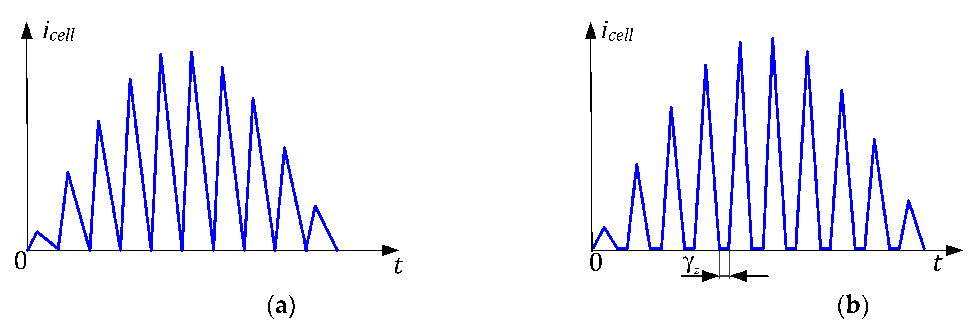
2.3. Charger Control Strategy

PFC converters operating in continuous conduction mode (CCM) need quite sophisticated control systems with three control loops and three feedbacks as shown in Figure 9a: Input voltage feedback, input current feedback and output voltage feedback. On the other hand, the PFC converter operating in discontinuous (DCM) or boundary conduction mode (BCM) needs only an output voltage control loop, as shown in Figure 9c. Therefore, the preferable operating mode of each SEPIC cell is boundary (BCM) or discontinuous conduction mode (DCM). Sine shape of input current, in this case, is achieved with a constant duty cycle (γ = const) [34], that simplifies the control system significantly [30]. Hence, the proposed control for the modular converter is based on forming N channel PWM sequences with constant duty cycle γ, each of them shifted by angle φ = 2πk/N, where k is cell number. Output power is regulated proportionally to the duty cycle γ.
The proposed control system calculates constant duty cycle for particular values of output voltage and desirable charge current. The control system should avoid operation in CCM. The difference between continuous and discontinuous mode may be easily detected when analyzing secondary voltage, see Figure 9b for CCM and Figure 9d for DCM. The discontinuous mode takes place if there are zero-voltage crossings while the transistor of the converter is off. The discontinuous mode detector, therefore, may be implemented based on the circuit containing a resistor and Zener diode.

2.4. Parameter Calculation and Component Selection

The charger is calculated for input voltage Uin = 230 V ±15%, output power P = 400 W, and maximum switching frequency fmax = 70 kHz. Output voltage Uout is not constant and may vary in the range 14….32 V. According to the restrictions mentioned above (Figure 7), the maximum duty cycle is equal to γmax = 0.5 and corresponds to the maximum output voltage Uout_max.
This limitation allows calculating the transformer ratio n:
n = ( U o u t _ max Δ U a d d ) 2 U i n 1 γ γ
where ΔUadd is the voltage drop on the output rectifier D1.
The minimum duty cycle γmin will take place at the maximum input Uin_max and the minimum output voltage Uout_min.
γ min = ( U o u t _ min + Δ U a d d ) n 2 U i n _ max + ( U o u t _ min + Δ U a d d )
Average current of one SEPIC cell in boundary mode Id_cell:
I d _ c e l l = P o u t / 4 N k f U i n η
where kf is the form factor. For sine voltage, kf = 1.11. Also, the tentative charger efficiency is η = 0.9.
Then the maximum current of a SEPIC cell Imax_cell can be found as:
I max _ c e l l = π I d _ c e l l
Value Imax_cell is equal to maximum current of transistor T1.
Inductance L with current Imax_cell limitation is calculated as:
L 1 = 2 U i n I max _ c e l l t o n
where ton is the time interval when transistor T1 is on.
For maximal frequency fmax = 70 kHz duty cycle is also at maximal value: γmax = 0.5. Therefore, ton = 0.5/fmax = 7.1 μs and L1 = 1.644 mH. The inductance of the primary winding LTF1 of the transformer TF is calculated based on the ratio that improves the shape of the input current of the converter:
L T F 1 = L U o u t _ min n 2 U i n _ max
The value of the capacitor C1 calculated for voltage ripple ΔUc1 = 15 V (<5%):
C 1 = I max _ c e l l γ min Δ U C 1 f min
By applying the desired charger parameters and constraints from Section 1.3 to Equations (5)–(11), the parameters of charger cell components are derived and listed in Table 2.
According to the charging requirements, the charging from 14 V to 32 V may be provided using three different operating modes: Constant output power, constant output current, constant output voltage and their combination.
The constant power mode is achieved with ton = constant, and varying duty cycle γ, which can be provided with pulse frequency modulation (PFM). The minimal operating frequency fmin is:
f min = f max γ min γ max .
The constant output voltage and current modes are provided with a more complicated modulation method, having varying ton and γ parameters.
The converter control algorithm has to simultaneously work in the specified mode (constant power, voltage) and preferably operate in the boundary conduction mode (BCM), since the current shape shown in Figure 10a delivers maximum power factor, efficiency and minimum component stresses. Whereas in continuous mode, the input current shape is distorted significantly, therefore this mode should be avoided [26]. The DCM shown in Figure 10b is permitted, but the duration of zero current interval γz should be minimized to increase performance.
A negative impact of zero current interval γz is mainly related to the increase of output circuit losses, additional overvoltage of input transistor (T1) and reduction of the power factor. Output circuit losses Pos are mostly defined by synchronous transistor (if used) on-state resistance rTs, that are increased with γz:
P O S = ( 1 γ ) 2 I max 2 1 γ γ z r T s ,
The steady-state voltage across the input transistor UT1 is also sensitive to the γz interval and defined as follows:
U T 1 = U i n + U o u t n = U i n 1 γ γ z ,
The relative overvoltage UT1* that is estimated as a ratio between the overvoltage with zero interval UT1z) and without it UT1(0), UT1* = UT1z)/UT1(0), is depicted in Figure 11a. Power factor value dependence on the duty cycle γ and cell number N in the BCM is shown in Figure 11b. As observed, for N = 4 in BCM, the power factor exceeds 0.99, which corresponds to the PFC requirements.
With zero current interval γz, the PF is reduced, as shown in Figure 12. For the N = 2 case, the power factor has the values in range (0.92; 0.999) and for N = 4 case, in range (0.97; 0.999). Since charging starts from minimal battery voltage Uo_min that corresponds to the duty cycle γmin and finishes with maximum battery voltage Uo_max and duty cycle γmax, the input current quality parameters PF and THD are varied during the charging. The average values PF_av and THD_av shown in Table 3 are estimated for different battery charging conditions and zero current interval duration γz. As it can be found from this table, the proposed converter fits the 15% THD requirement of International Electro-technical Commission (IEC) 61000-3-2 standard for Class A/D electrical equipment.
It should be noted, that in the constant voltage mode (close to the end of charging process), the output power is decreased and tends to zero, as a result Equation (9), that determines ton interval for BCM, tends to zero as well. This makes the operating frequency f tend to infinity, as shown in Figure 13a. Therefore, in the practical application, it is necessary to limit the operating frequency to the value fmax, which is possible with the introduction of γz. As observed in Figure 13b,c, the BCM for certain average current value Iav is provided with a shorter period duration TBCM than in the TDCM, TBCM < TDCM, hence DCM may be effectively used for frequency limitation in constant voltage charging mode.

3. Evaluation Methods and Results
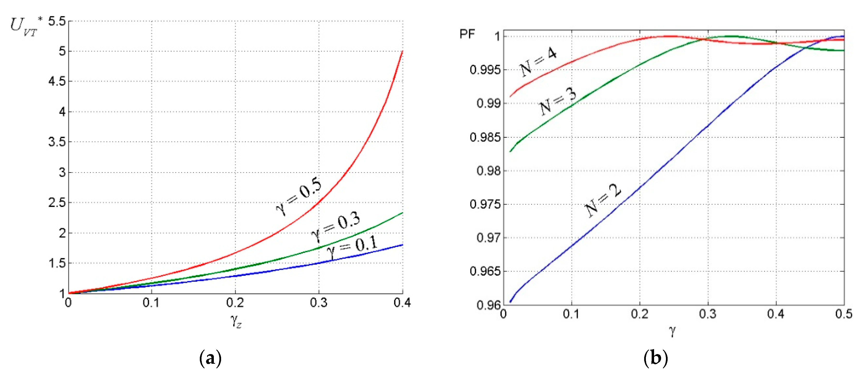
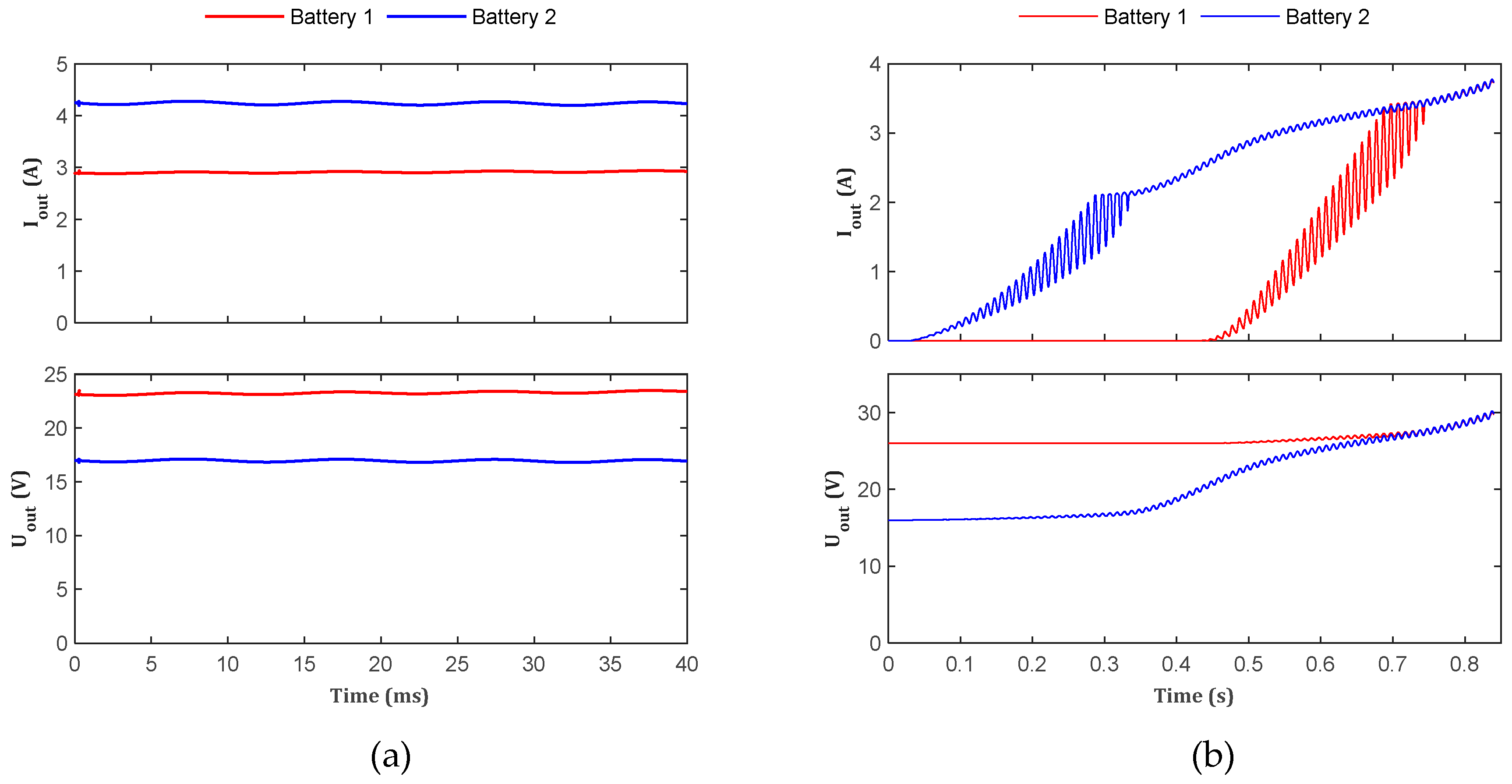
The above described idea of balanced charging current distribution between battery packs in conjunction with simultaneous PFC, based on multi-cell SEPIC topology has been verified by means of simulation, as well as experimentally. The conditions of the evaluation and the corresponding results are presented in the following sections.

3.1. Simulation

In order to verify the proposed concept of the charger and its control strategy, a PSIM 11 model of the proposed converter concept has been created. The parameters of the model have been defined in accordance with the values derived in the previous section. The differently pre-charged capacitors with inner resistance Rcap = 0.1 Ohm were applied instead of batteries during the simulation in order to speed up calculation process and representation of the data. Particular features of the model are the minimal required cell number (N = 2) with two secondary windings for each SEPIC cell, so that the model shown in Figure 14a corresponds to the charger concept, presented in Figure 5.
The model of the two-cell converter additionally contained two voltage sources Gen1 and Gen2 that created initial voltages at the cell outputs. The control system consisted of two sawtooth-wave voltage sources S1 and S2, which were connected via AND gate to comparator DA1, allowing the generation of a PWM signal with a smooth increase of duty cycle γ from zero to nominal value. Time delay block “Delay” created a half-period delay for transistor of the second cell. The charging process was stopped when output voltage measured with a resistive sensor exceeded the reference voltage Uref.
The simulated input current and voltage waveforms with γ = 0.5 are presented in Figure 15a,b. As it can be seen, the input current was nearly sinusoidal with low distortion at switching frequency. At lower operating power (when batteries were almost charged) the γ should have been reduced, which strongly affected the input current shape, Figure 15b. As mentioned in the previous section, the input current distortion can be reduced by increasing the operating frequency. The input current with the frequency increased to 150 kHz is shown in Figure 15d, which allowed THD to be improved from 0.425 to 0.297.
Figure 16a depicts operation with differently charged and separately connected batteries. The cell power mainly depended on duty cycle and input voltage, therefore even for different loads the output power was approximately equal. In Figure 16b a battery self-balancing feature is demonstrated. In this analysis the batteries were substituted with relatively large and differently pre-charged capacitances, as shown in Figure 14a, to reduce simulation effort. Similar behavior for actual batteries is expected. Firstly, only Battery 1 with smaller initial voltage was being charged, when battery voltages were balanced the batteries were starting to charge simultaneously. When Battery 2 started charging its current had a pulsed shape because of output voltage ripple and small battery internal resistance. Therefore, with positive voltage ripple when the output voltage exceeded the Battery 2 initial voltage, the current increase was relatively sharp, whereas with negative voltage ripple output current with the same speed aimed to zero. Finally, when the output voltage became equal to the initial Battery 2 voltage during the whole switching period, the output current started to have a smooth shape.

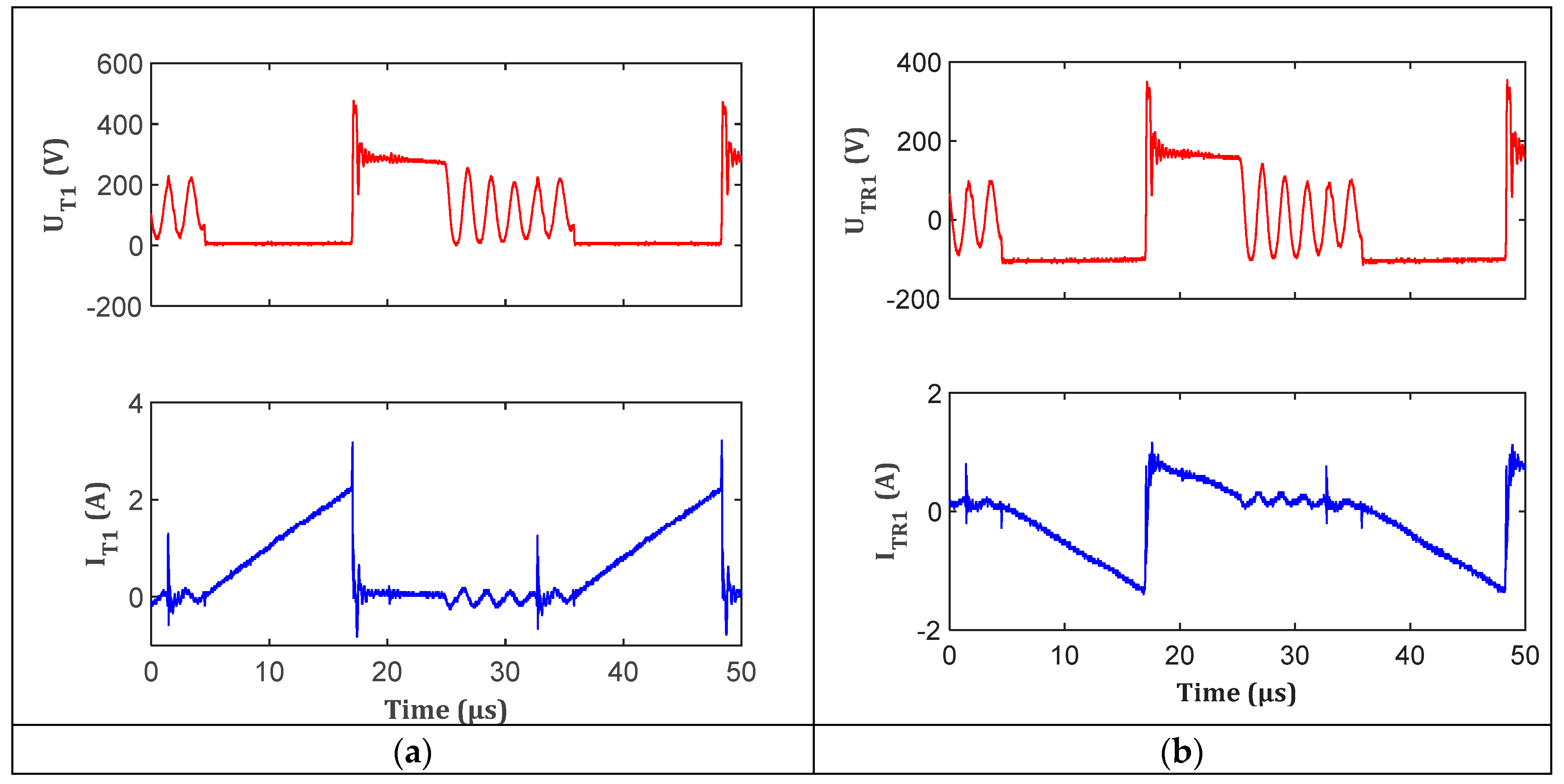
3.2. Experimental Verification

In order to evaluate and verify the of operation of the charger, an experimental prototype of the converter with two SEPIC cells was built. The components of the prototype are briefly described in Table 4. As in the case of simulation, the differently pre-charged capacitors were applied instead of batteries during the experiments in order to speed up the measurement processes. The photo of the charger is given in Figure 17, while its parameters and components are listed in Table 3. The control signal was applied to power transistors with 180° phase shift and duty cycle ranging from 0 to 0.5. This was realized with microcontroller STM32F334 utilizing timer TIM3. The timer had a clock frequency of 72 MHz and formed the carrier frequency of 64 kHz. The channels were operating in “center aligned 3” mode, with the first one in PWM1 and the second one in PWM2 mode. By applying Capture-Compare Register (CCR) register values for corresponding timers equal to “duty_cycle” and “T – duty_cycle” (where T was the counter overflow value and “duty_cycle” was the numeric value of pulse width), the required 180° phase shift was formed. To reduce the effect of transient processes at start-up, the soft-start was implemented with the ramp from 0 to “duty_cycle” within 700 ms.
The experimental input current and voltage waveforms are presented in Figure 18a,b. The input current waveforms at different operating conditions are depicted in Figure 18c,d. As observed, the characteristics were close to the simulated ones presented in the previous section. Figure 19 demonstrates the forming of continuous input current with reduced current ripple by two interleaved cells operating in DCM. The transistor and transformer currents and voltages over the switching period are shown in Figure 20a,b, respectively. The overvoltage spike observed after turn-off caused by transformer leakage inductance was damped by RCD snubber to keep it within allowable limits of the chosen transistor.
Figure 21a demonstrates operation with differently charged and separately connected capacitors, while Figure 21b shows the balancing process. As it can be found from these figures, the converter behavior was in line with expected characteristics from the previous section.

4. Discussion, Conclusions and Considerations for Future Works

Despite the first impression of apparent simplicity, the considered problem–design and implementation of a double channel charger for cost-effective hardware-reconfigurable adaptive power-assist wheelchair can be regarded as a challenging one. The main factors that lead to this conclusion are various functional and technical constraints that have to be simultaneously addressed. Requirement of unity power factor and low harmonic distortion of the input current requires active current shaping with switched-mode converters. Size limitation in conjunction with limited cooling opportunities imposes constraints on the minimal system efficiency. At the same time, price limitations and different initial state of the charge of battery packs instigates the use of relatively simple single-stage converter topologies with modular structure. The proposed charger concept has the capability to address these challenges:
  • Single-stage SEPIC features relatively low component count and simple control;
  • multi-cell configuration reduces the input current ripple, harmonic distortion and achieves unity power factor;
  • natural charge balancing of batteries with different state of charge is provided;
  • operation in boundary and discontinuous conduction modes simplifies the design and can provide sufficient conversion efficiency.
The proposed charger has been studied with the help of simulation and verified with a scaled laboratory prototype. The experimental operation was close to the estimated characteristics. The average efficiency of the converter prototype was around 82%. The relatively low efficiency can be explained by significant losses in the RCD snubber and rectifier diodes. The application of a regenerative snubber, which will be common for all the cells, together with a synchronous rectifier will be addressed in the following work. According to estimations the efficiency of the final system is expected to be in the range of 90%–92%. Another research direction would be the identification of the optimal operating characteristics (frequency, duty cycle) dependent on the operation mode from the point of view of input current quality and efficiency.

Author Contributions

Conceptualization, I.G. and A.B.; investigation, A.B. and I.V.; methodology, I.V.; software, D.Z.; supervision, I.G.; Validation, A.B. and D.Z.; writing – original draft, I.G.

Funding

The preparing of this publication is supported by the European Regional Development Fund (ERDF) within the contract Nr. 1.1.1.1/16/A/147 “Research and Development of Electrical, Information and Material Technologies for Low Speed Rehabilitation Vehicles for Disabled People” and by the Estonian Centre of Excellence in Zero Energy and Resource Efficient Smart Buildings and Districts, ZEBE, grant 2014-2020.4.01.15-0016 funded by the European Regional Development Fund.

Conflicts of Interest

Authors declare no conflict of interest.

References

  1. World Health Organization. World report on disability 2011. Am. J. Phys. Med. Rehabil. Assoc. Acad. Physiatr. 2011, 91, 549. [Google Scholar]
  2. Kraus, L.; Lauer, E.; Coleman, R.; Houtenville, A. 2017 Disability Statistics Annual Report; University of New Hampshire: Durham, NH, USA, 2018. [Google Scholar]
  3. Disability Statistics 2015. Available online: http://ec.europa.eu/eurostat/statistics-explained/index.php/Disability_statistics (accessed on 27 February 2019).
  4. Dudgeon, B.J.; Deitz, J.C.; Dimpfel, M. Wheelchair Selection. In Occupational Therapy for Physical Dysfunction, 7th ed.; Lippincott Williamns & Wilkins Editors: Philadelphia, PA, USA, 2013. [Google Scholar]
  5. Ding, D.; Cooper, R.A. Electric powered wheelchairs. IEEE Control Syst. Mag. 2005, 25, 22–34. [Google Scholar]
  6. Hou, R.; Shi, X.; Krishnamurthy, M. Design and implementation of a novel power assisted drivetrain for a wheelchair. In Proceedings of the IEEE Transportation Electrification Conference and Expo (ITEC), Dearborn, MI, USA, 18–20 June 2012; pp. 1–6. [Google Scholar]
  7. Yang, Y.-P.; Lin, H.-C.; Tsai, F.-C.; Lu, C.-T.; Tu, K.-H. Design and integration of dual power wheels with rim motors for a powered wheelchair. IET Electr. Power Appl. 2012, 6, 419. [Google Scholar] [CrossRef]
  8. Galkin, I.; Podgornovs, A.; Blinov, A.; Vitols, K.; Vorobyov, M.; Kosenko, R. Considerations regarding the concept of cost-effective power-assist wheelchair subsystems. Electr. Control Commun. Eng. 2018, 14, 71–80. [Google Scholar] [CrossRef]
  9. Vorobyov, M.; Galkin, I. Concept of cost-effective power-assisted wheelchair: Human-in-the-loop subsystem. In Proceedings of the 5th IEEE Workshop on Advances in Information, Electronic and Electrical Engineering (AIEEE), Riga, Latvia, 24–25 November 2017; pp. 1–5. [Google Scholar]
  10. Vitols, K.; Podgornovs, A. Concept of cost-effective power-assist wheelchair’s electrical subsystem. In Proceedings of the 5th IEEE Workshop on Advances in Information, Electronic and Electrical Engineering (AIEEE), Riga, Latvia, 24–25 November 2017; pp. 1–4. [Google Scholar]
  11. Geidarovs, R.; Podgornovs, A.; Galkin, I. Simulation and Initial Evaluation of Modular Motor-Generator for Cost-Effective Power-Assist Wheelchair. In Proceedings of the IEEE 59th International Scientific Conference on Power and Electrical Engineering of Riga Technical University (RTUCON), Riga, Latvia, 12–13 November 2018; pp. 1–5. [Google Scholar]
  12. Vitols, K. Analysis of Battery Cell Configuration in Respect to Powered Wheelchair Drive Efficiency. J. Pol. Acad. Sci. under review.
  13. International Standard ISO7176: Wheelchairs. Part 4: Energy Consumption of Electric Wheelchairs and Scooters for Determination of Theoretical Distance Range. Available online: https://www.iso.org/standard/40991.html (accessed on 27 February 2019).
  14. European Standard prEN 12184:2004: Electrically Powered Wheelchairs, Scooters and Their Chargers—Requirements and Test Methods. Available online: https://www.sustainable-design.ie/fire/ElectricWheelchairs_DRAFTprEN12184.pdf (accessed on 27 February 2019).
  15. Latvian State Standard LVS EN 12184: Electrically Powered Wheelchairs, Scooters and Their Chargers—Requirements and Test Methods. Available online: https://infostore.saiglobal.com/preview/98696469803.pdf?sku=857543_SAIG_NSAI_NSAI_2040022 (accessed on 27 February 2019).
  16. Chub, A.; Vinnikov, D.; Liivik, E.; Jalakas, T. Multiphase Quasi-Z-Source DC–DC Converters for Residential Distributed Generation Systems. IEEE Trans. Ind. Electr. 2018, 65, 8361–8371. [Google Scholar] [CrossRef]
  17. Chub, A.; Vinnikov, D.; Kosenko, R.; Liivik, E.; Galkin, I. Bidirectional DC-DC Converter for Modular Residential Battery Energy Storage Systems. IEEE Trans. Ind. Electr. 2019. accepted. [Google Scholar] [CrossRef]
  18. Singh, B.; Singh, S.; Chandra, A.; Al-Haddad, K. Comprehensive Study of Single-Phase AC-DC Power Factor Corrected Converters with High-Frequency Isolation. IEEE Trans. Ind. Inform. 2011, 7, 540–556. [Google Scholar] [CrossRef]
  19. Canales, F.; Abud, D.; Arau, J.; Jimenez, G. Design of a two stage, 1 kW battery charger with power factor correction. In Proceedings of the Fifth International Conference on Power Electronics and Variable-Speed Drives, London, UK, 26–28 October 1994; pp. 626–631. [Google Scholar]
  20. Gautam, D.; Musavi, F.; Edington, M.; Eberle, W.; Dunford, W.G. An automotive on-board 3.3 kW battery charger for PHEV application. In Proceedings of the IEEE Vehicle Power and Propulsion Conference, Chicago, IL, USA, 6–9 September 2011; pp. 1–6. [Google Scholar]
  21. Lee, B.; Lee, J.; Kang, D. An Isolated PFC Converter with Harmonic Modulation Technique for EV Chargers. In Proceedings of the International Power Electronics Conference (IPEC-Niigata 2018 -ECCE Asia), Niigata, Japan, 20–24 May 2018; pp. 3030–3033. [Google Scholar]
  22. Wang, X.; Ben, H.; Meng, T.; Liu, B. An auxiliary link based on flyback circuit with voltage spike suppression for single-phase isolated full-bridge boost PFC. In Proceedings of the IEEE 8th International Power Electronics and Motion Control Conference (IPEMC-ECCE Asia), Hefei, China, 22–26 May 2016; pp. 1333–1337. [Google Scholar]
  23. Dusmez, S.; Li, X.; Akin, B. A Fully Integrated Three-Level Isolated Single-Stage PFC Converter. IEEE Trans. Power Electr. 2015, 30, 2050–2062. [Google Scholar] [CrossRef]
  24. Jindong Zhang, M.; Jovanovic, M.; Lee, F.C. Comparison between CCM single-stage and two-stage boost PFC converters. In Proceedings of the APEC ’99, Fourteenth Annual Applied Power Electronics Conference and Exposition, 1999 Conference Proceedings (Cat. No.99CH36285), Dallas, TX, USA, 14–18 March 1999; Volume 1, pp. 335–341. [Google Scholar]
  25. Qiao, C.; Smedley, K.M. A topology survey of single-stage power factor corrector with a boost type input-current-shaper. IEEE Trans. Power Electr. 2001, 16, 360–368. [Google Scholar] [CrossRef]
  26. Simonetti, D.S.L.; Sebastian, J.; dos Reis, F.S.; Uceda, J. Design criteria for SEPIC and Cuk converters as power factor preregulators in discontinuous conduction mode. In Proceedings of the 1992 International Conference on Industrial Electronics, Control, Instrumentation, and Automation, San Diego, CA, USA, 9–13 November 1992; Volume 1, pp. 283–288. [Google Scholar]
  27. Tibola, G.; Lemmen, E.; Barbi, I. Three-phase isolated DCM SEPIC converter for high voltage applications. In Proceedings of the IEEE Energy Conversion Congress and Exposition (ECCE), Milwaukee, WI, USA, 18–22 September 2016; pp. 1–8. [Google Scholar]
  28. Li, C.; Zhang, Y.; Cao, Z.; Xu, D. Single-Phase Single-Stage Isolated ZCS Current-Fed Full-Bridge Converter for High-Power AC/DC Applications. IEEE Trans. Power Electr. 2017, 32, 6800–6812. [Google Scholar] [CrossRef]
  29. Ayyanar, R.; Mohan, N.; Sun, J. Single-stage three-phase power-factor-correction circuit using three isolated single-phase SEPIC converters operating in CCM. In Proceedings of the 2000 IEEE 31st Annual Power Electronics Specialists Conference. Conference Proceedings (Cat. No.00CH37018), Galway, Ireland, 23 June 2000; Volume 1, pp. 353–358. [Google Scholar]
  30. Simonetti, D.S.L.; Sebastian, J.; Uceda, J. The discontinuous conduction mode Sepic and Cuk power factor preregulators: Analysis and design. IEEE Trans. Ind. Electron. 1997, 44, 630–637. [Google Scholar] [CrossRef]
  31. Chen, R.; Lai, J. Analysis and design of DCM SEPIC PFC with adjustable output voltage. In Proceedings of the IEEE Applied Power Electronics Conference and Exposition (APEC), Charlotte, NC, USA, 15–19 March 2015; pp. 477–484. [Google Scholar]
  32. Shi, C.; Khaligh, A.; Wang, H. Interleaved SEPIC Power Factor Preregulator Using Coupled Inductors in Discontinuous Conduction Mode with Wide Output Voltage. IEEE Trans. Ind. Appl. 2016, 52, 3461–3471. [Google Scholar] [CrossRef]
  33. Ryu, D.-K.; Kim, Y.-H.; Kim, J.-G.; Won, C.-Y.; Jung, Y.-C. Interleaved Active Clamp Flyback Inverter using a Synchronous Rectifier for a Photovoltaic AC Module System. In Proceedings of the 8th International Conference on Power Electronics—ECCE Asia, The Shilla Jeju, Korea, 30 May–3 June 2011; pp. 2631–2636. [Google Scholar]
  34. Verbytskyi, I.; Bondarenko, O.; Liivik, E. Control features of multicell-type current regulator for resistance welding. In Proceedings of the IEEE 58th International Scientific Conference on Power and Electrical Engineering of Riga Technical University (RTUCON), Riga, Latvia, 12–13 October 2017; pp. 1–5. [Google Scholar]
Figure 1. Currently available wheelchairs: (a) Cost availability (green—good, yellow—questionable, red—bad), (b) power consumption (green—low/no, yellow—average, red—high).
Energies 12 01526 g001
Figure 2. Configurable wheelchair and parts of its electrical subsystem: 1—Electrical motor-generator and its electronic driver (1A—rotor, 1B—stator parts), 2—batteries and the corresponding Battery Management Systems (BMS), 3—charger (3A—charger, 3B—its compartment.
Energies 12 01526 g002
Figure 3. Typical (a) and proposed (b) charging system configurations.
Energies 12 01526 g003
Figure 4. A single-ended primary-inductor converter (SEPIC) cell: (a) Typical, (b) isolated, (c) multiple output.
Energies 12 01526 g004
Figure 5. Simplified configuration of the proposed charger.
Energies 12 01526 g005
Figure 6. Generalized operation principle of a multi-cell interleaved SEPIC converter.
Energies 12 01526 g006
Figure 7. Error δ for input borderline current of N = 2–6 interleaved cells [34].
Energies 12 01526 g007
Figure 8. Principal charge balancing timing diagram: (a) voltage of two batteries with different charge; (b) cell charging current.
Energies 12 01526 g008
Figure 9. Generalized power factor correction (PFC) control system: (a) Continuous conduction mode (CCM) and (b) generalized corresponding output winding voltage; (c) discontinuous conduction mode (DCM) and (d) generalized corresponding output winding voltage.
Energies 12 01526 g009
Figure 10. Input current shape of a cell: (a) Boundary conducting mode; (b) discontinuous conducting mode with zero current interval γz.
Energies 12 01526 g010
Figure 11. Input transistor relative overvoltage UT1* versus duty cycle γ and zero current interval duration γz (a); power factor value versus duty cycle γ and cell number N (b).
Energies 12 01526 g011
Figure 12. Power factor value as function of γ and γz: (a) Two cell converter N = 2, (b) four cell converter, N = 4.
Energies 12 01526 g012
Figure 13. Generalized charging process with frequency limitation in constant voltage operating mode (a); average current (power) regulation principle: Boundary conduction mode (BCM) (b) and DCM (c).
Energies 12 01526 g013
Figure 14. PSIM model: (a) SEPIC power circuit; (b) corresponding control system.
Energies 12 01526 g014
Figure 15. Simulated input current (a) and voltage (b) at P = 200 W; (c) input current at P = 50 W (γ = 0.25 and f = 64 kHz); (d) input current at P = 50 W (γ = 0.37 and f = 150 kHz).
Energies 12 01526 g015
Figure 16. Output current and voltage waveforms of two separate SEPIC cells operating with different loads (a); charge balancing at the output capacitances of parallel connected cells (b).
Energies 12 01526 g016
Figure 17. Photo of the experimental converter prototype with two SEPIC cells.
Energies 12 01526 g017
Figure 18. Experimental waveforms of input current (a) and voltage (b) at P = 200 W; (c) input current at P = 50 W (γ = 0.25 and f = 64 kHz); (d) input current at P = 50 W (γ = 0.35 and f = 150 kHz).
Energies 12 01526 g018
Figure 19. Experimental waveforms of two interleaved transformer currents forming continuous input current (P = 200 W).
Energies 12 01526 g019
Figure 20. Experimental waveforms of the input transistor (T1) voltage and current (a) and corresponding transformer TR1 voltage and current (b) (P = 200 W).
Energies 12 01526 g020
Figure 21. Output current and voltage waveforms of two separate SEPIC cells operating with different loads (a), charge balancing at the output capacitances of parallel connected cells (b).
Energies 12 01526 g021
Table 1. Operation parameters of the wheelchair.
ParameterVariableData SourceValue
Cruise speed (>70%)vLVS121845 km/h = 1.4 m/s
Max speedvmaxLVS1218415 km/h = 4.2 m/s
Operation timeTLVS121841 h
MassmTask definition120 kg
Charge/discharge efficiencyηBBattery datasheet0.8
Coefficient of rolling resistance (rubber-concrete)FTask definition15…35 mm
Wheel radiusRTask definition300 mm
Table 2. Parameters of the main converter components.
ComponentValue
L11.6 mH
T11.4 A, 745 V
C10.25 μF, 400 V
TFn = 0.1, LTF1 = 0.75 mH
D1112.5 A, 70 V
C26.8 mF, 32 V
Table 3. Average power factor (PF) and Total Harmonic Distortion (THD) during the charging.
Initial SOC, %Parameter N = 2N = 4
γz = 0γz = 0.15γz = 0.3γz = 0γz = 0.15γz = 0.3
0%PF_av
THD_av
0.9955
0.094
0.9947
0.102
0.9771
0.213
0.9983
0.057
0.9978
0.065
0.9962
0.086
30%PF_av
THD_av
0.9989
0.046
0.9970
0.077
0.9745
0.224
0.9987
0.051
0.9978
0.065
0.9971
0.076
80%PF_av
THD_av
0.9997
0.023
0.9962
0.087
0.9727
0.232
0.9989
0.047
0.9980
0.064
0.9972
0.075
Table 4. Main parameters and components of the experimental converter.
ParameterVariableType/Value
Input voltageUin230 V AC (±15%)
Output voltageUout14…32 V DC
Operating frequencyfmax64 kHz
Transformer turns ration60:7:7, 0.7 mm copper wire
Transformer inductanceLTR840 µH
Transformer leakage inductanceLlk20 µH
Transformer/inductor core-Е30-15-7
Inductance L11.7 mH/94 turns, 0.55 mm copper wire
CapacitanceC1MCKSK450M4R7G20S, 450 V/4.7 µF
Output capacitanceC2UVR1V103MRD6, 35 V/10 mF
Primary MOSFETT1C3M0120090D
Secondary diodeD1STPS30H100CW
MOSFET driver -IRS44273L
Microcontroller-STM32F334

