A Comprehensive VSM Control Strategy Designed for Unbalanced Grids


Abstract
:1. Introduction
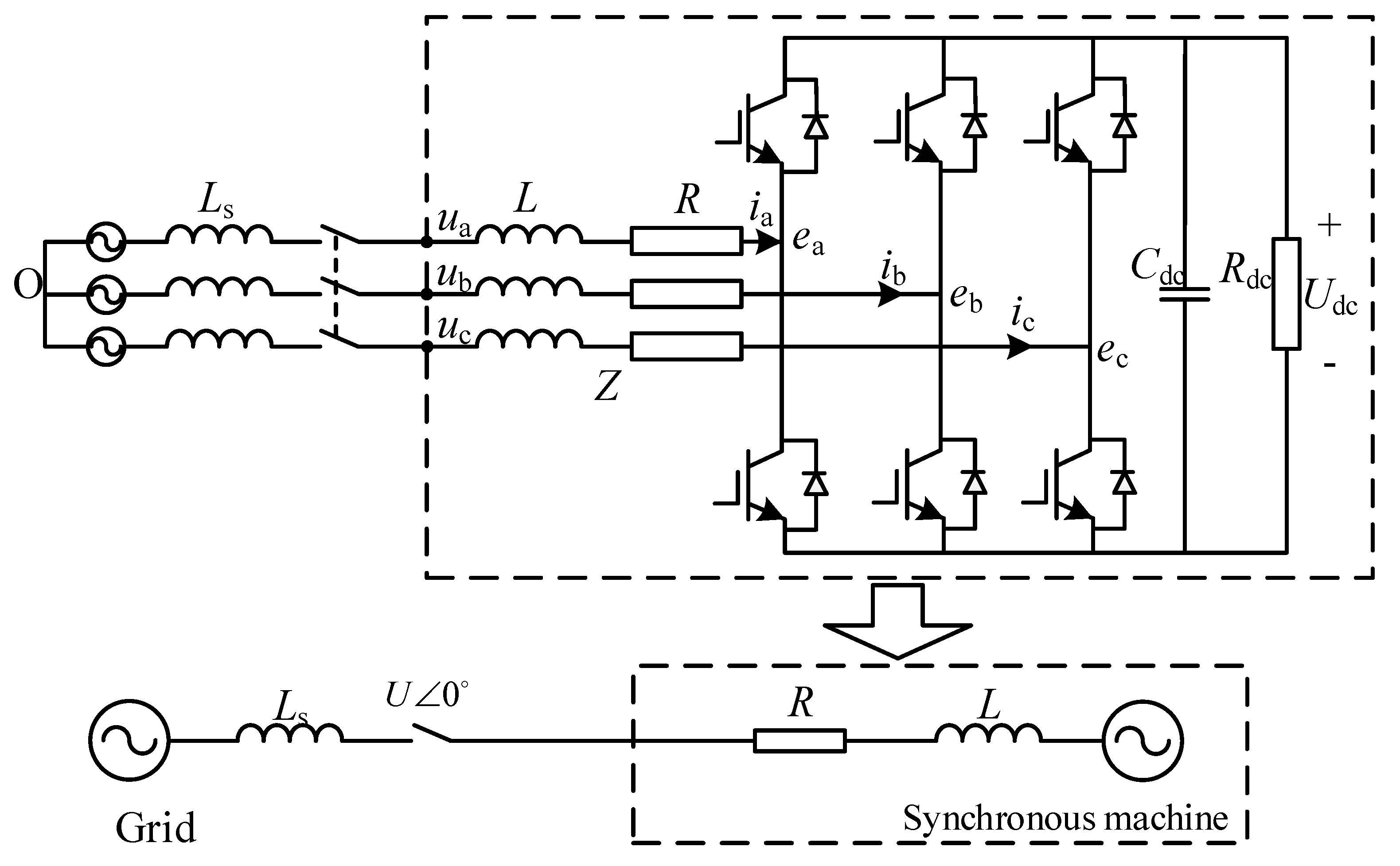
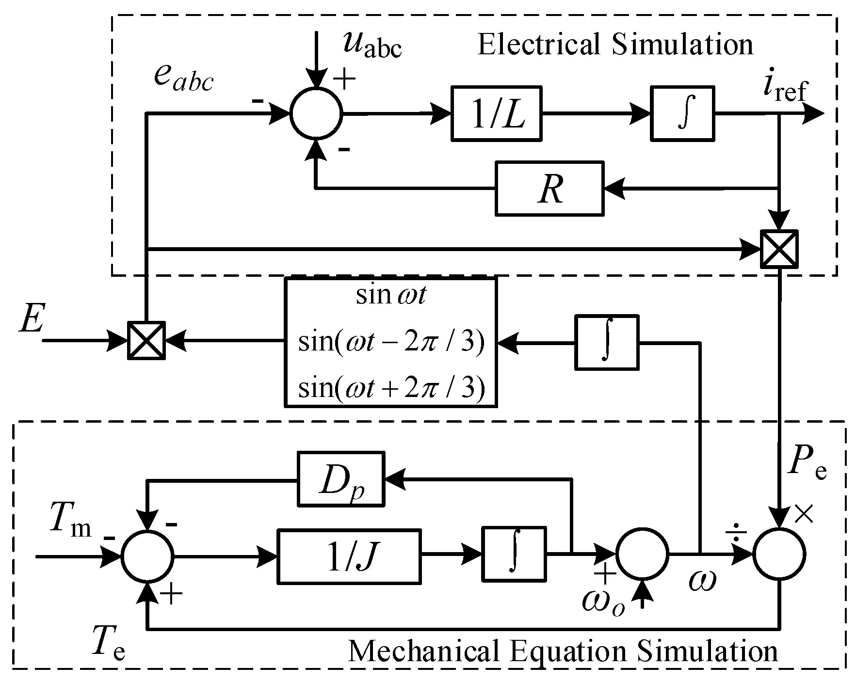
2. Principle and Control of VSMs
3. Analysis of the Unbalanced Grid
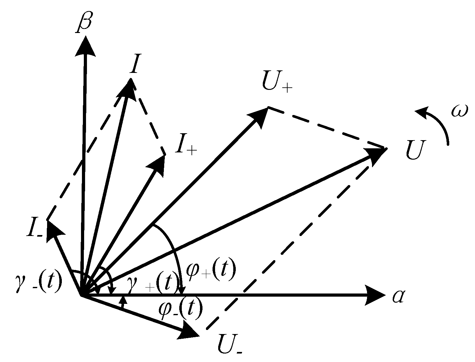
3.1. Mathematic Model of Unbalanced Voltage
3.2. Power Oscillation Analysis
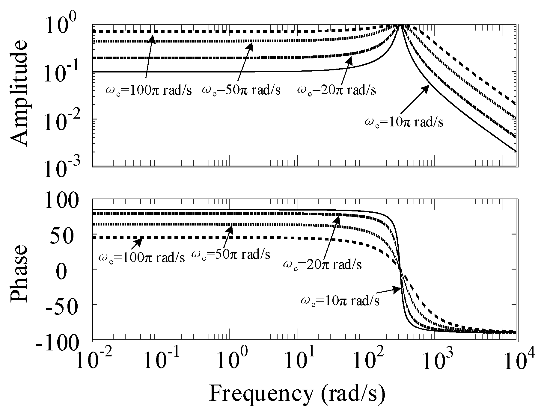
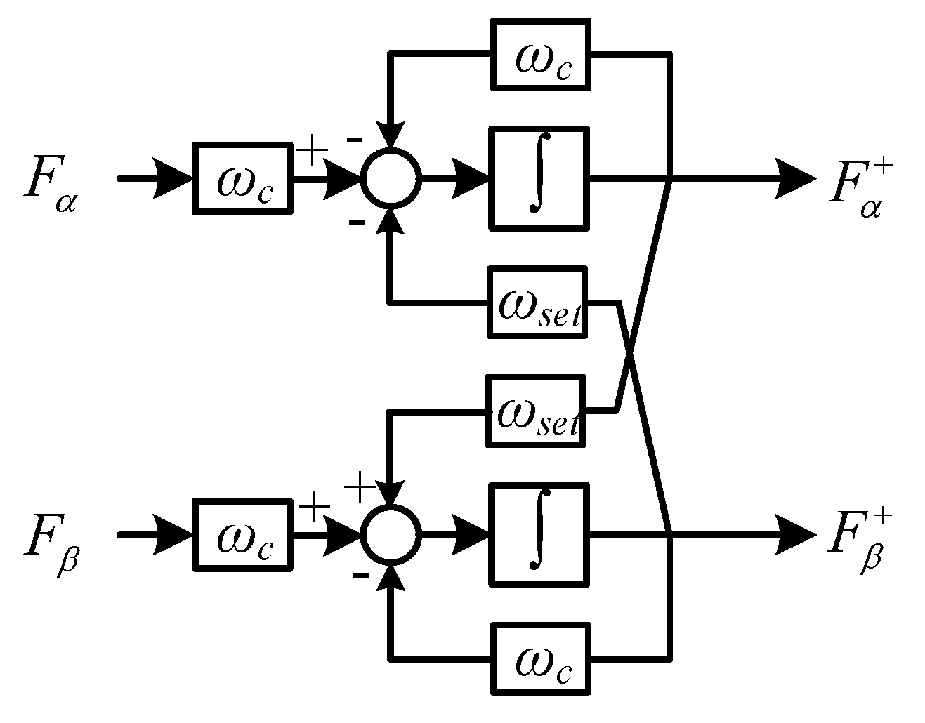
3.3. Positive and Negative Sequence Separation
4. VSM Control under Unbalanced Conditions
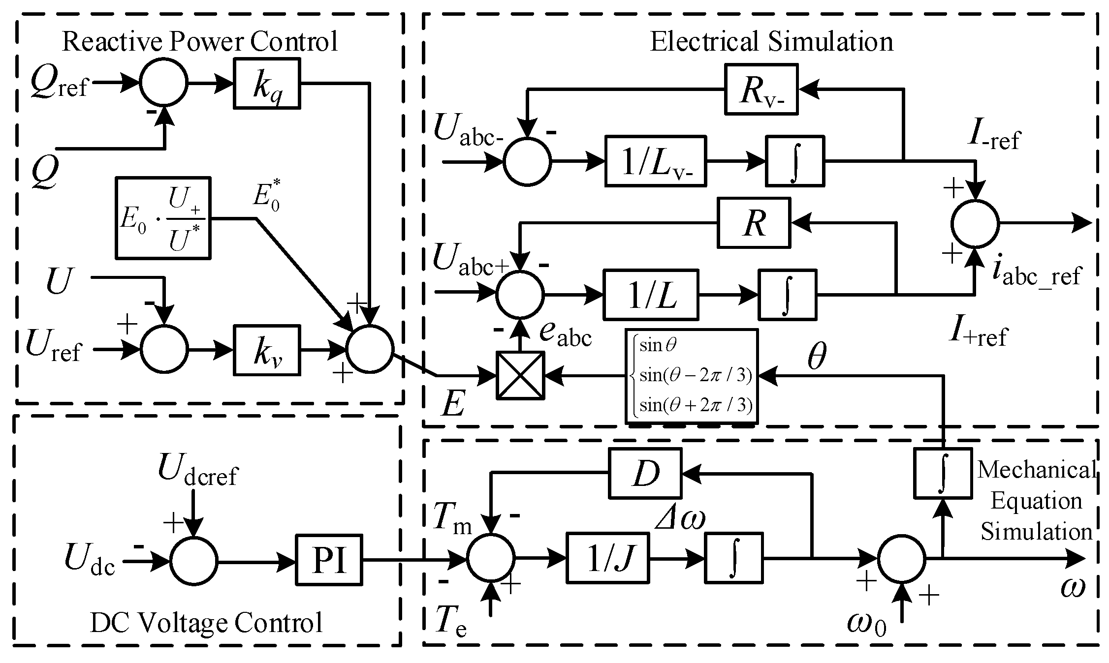
4.1. Suppress the Current Negative Sequence
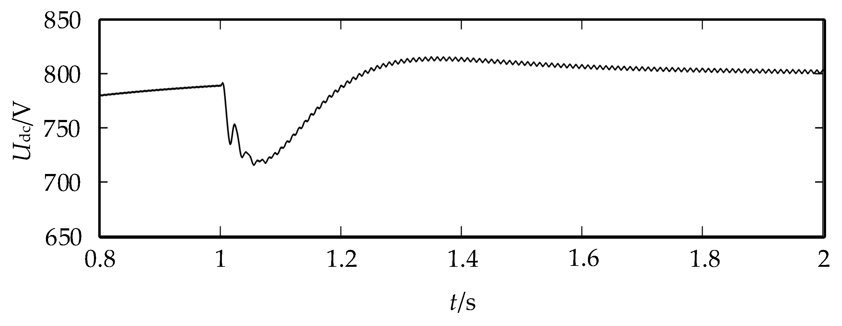
4.2. Suppress DC Voltage Ripples
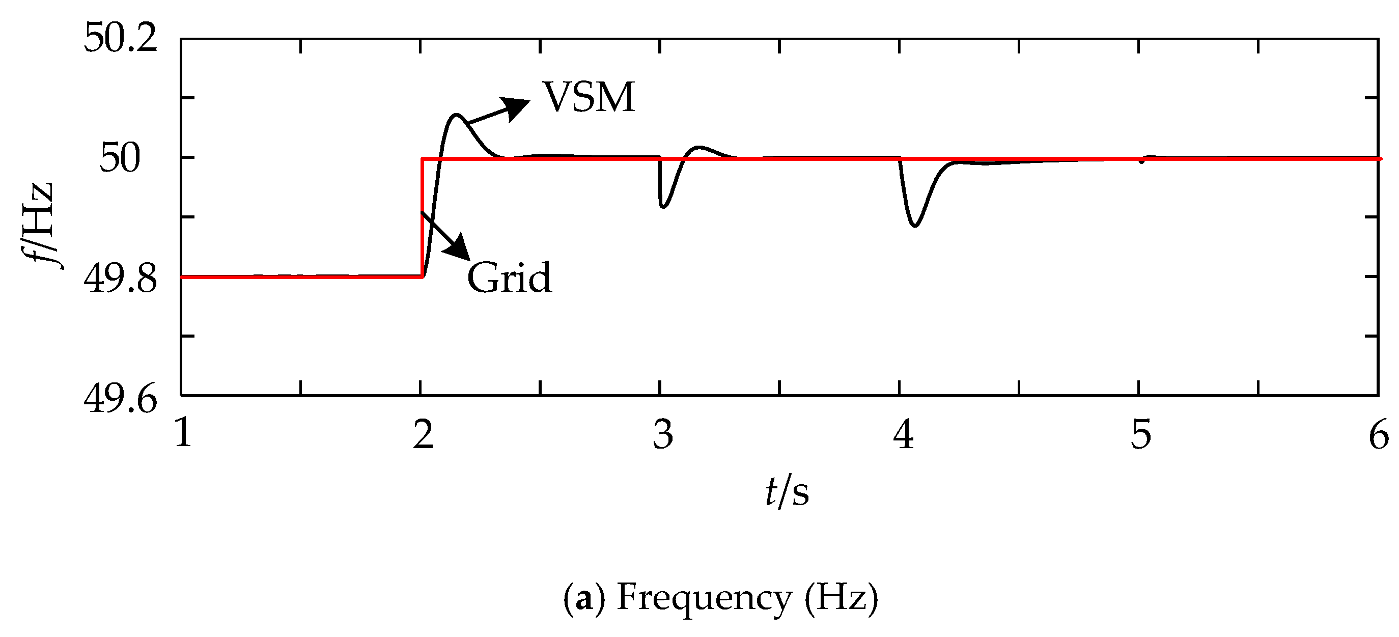
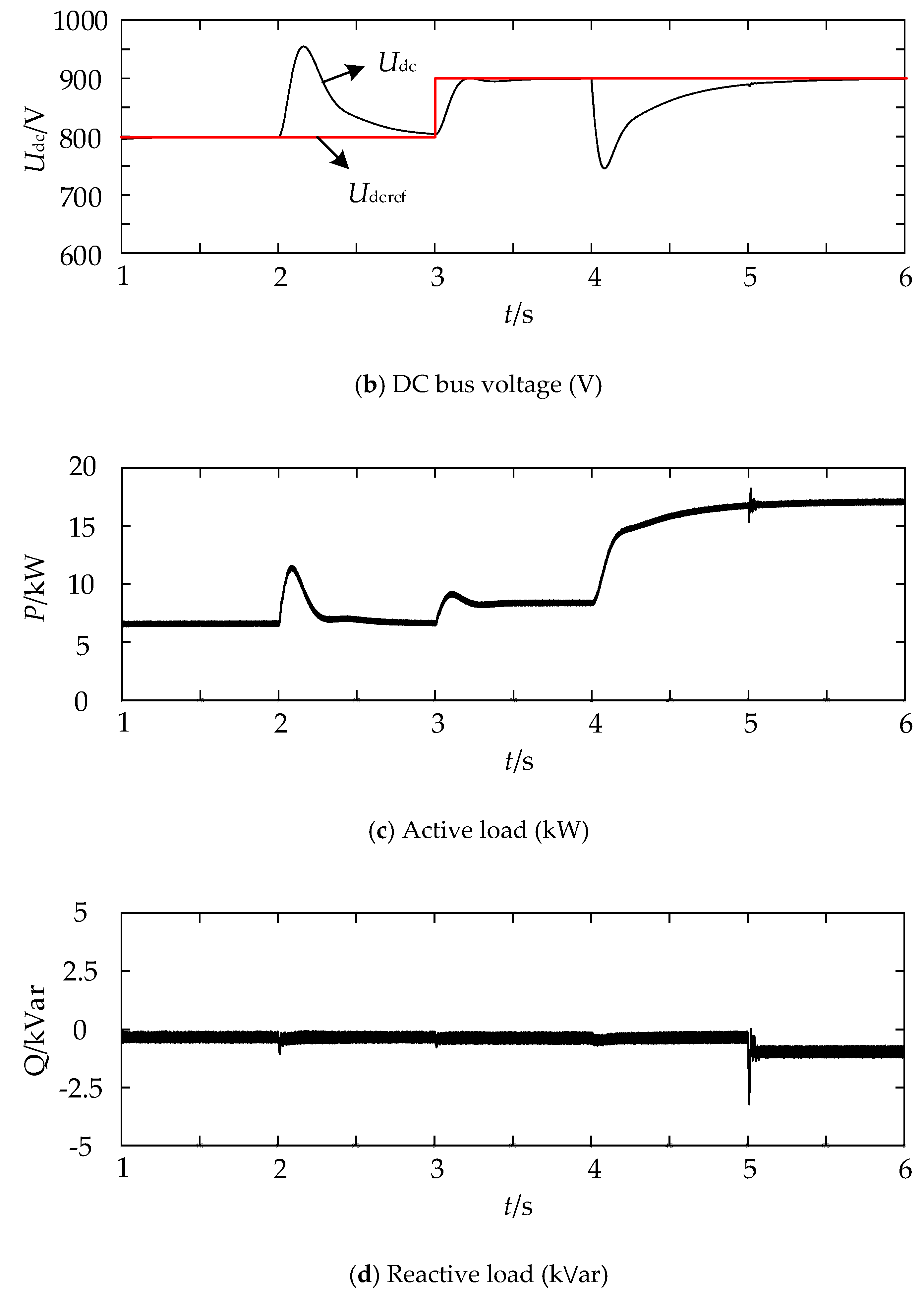
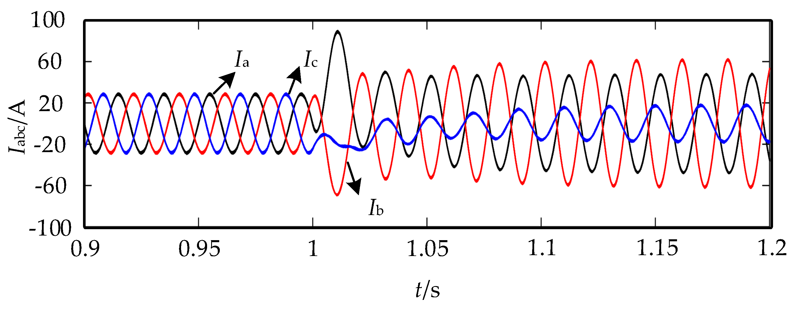
5. Simulation
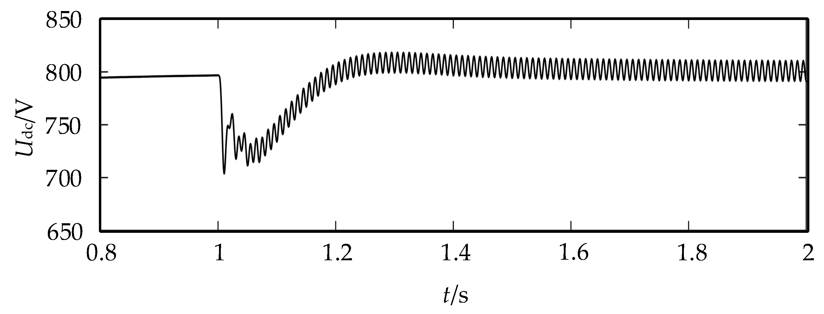
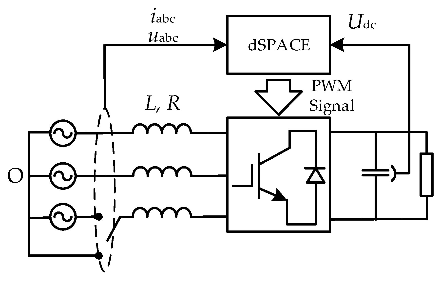
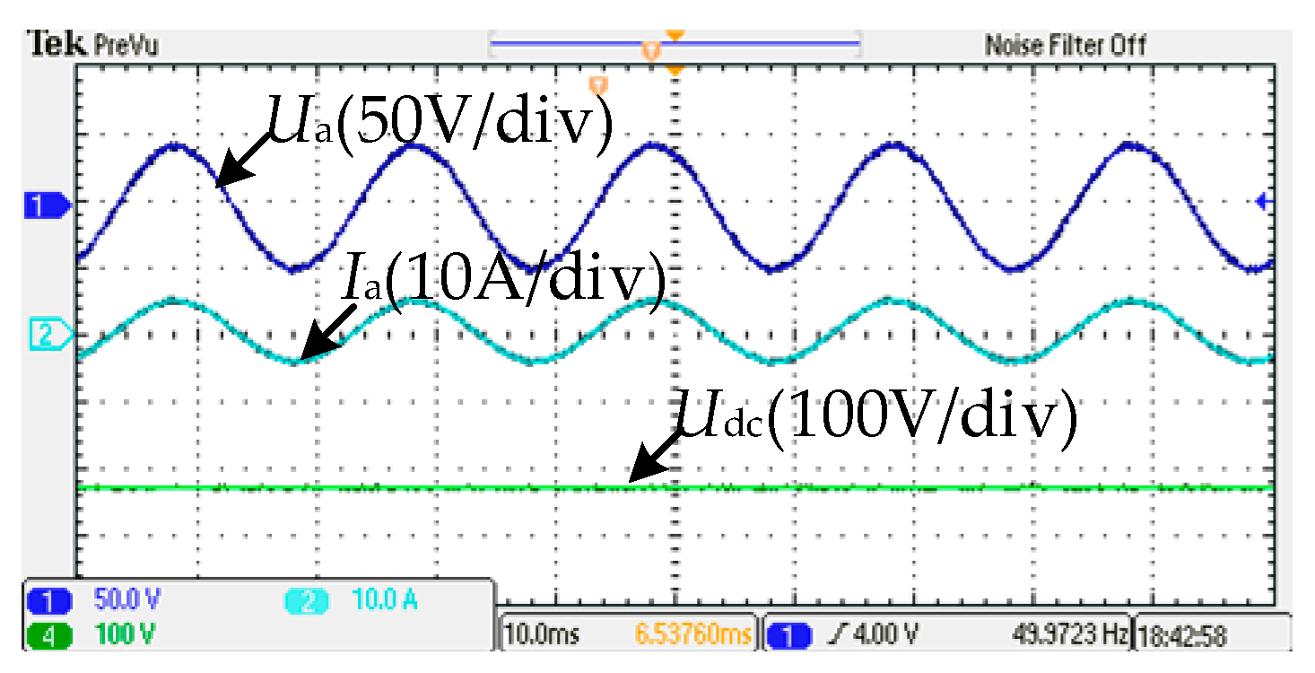
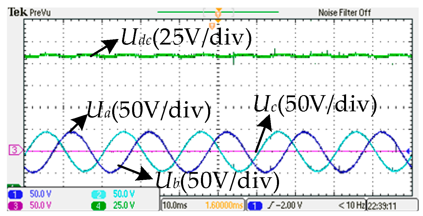
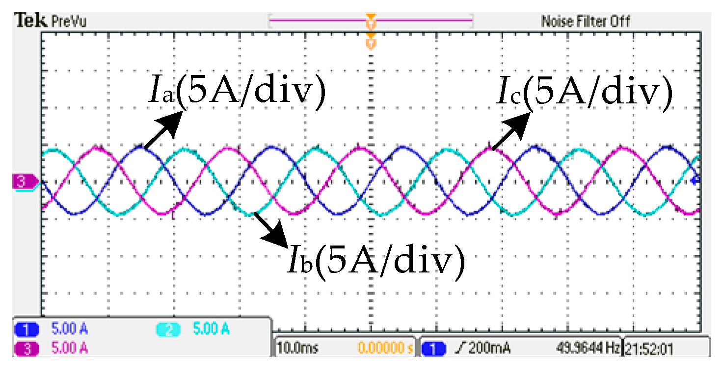
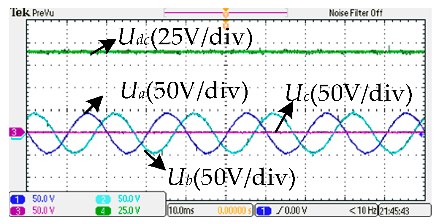
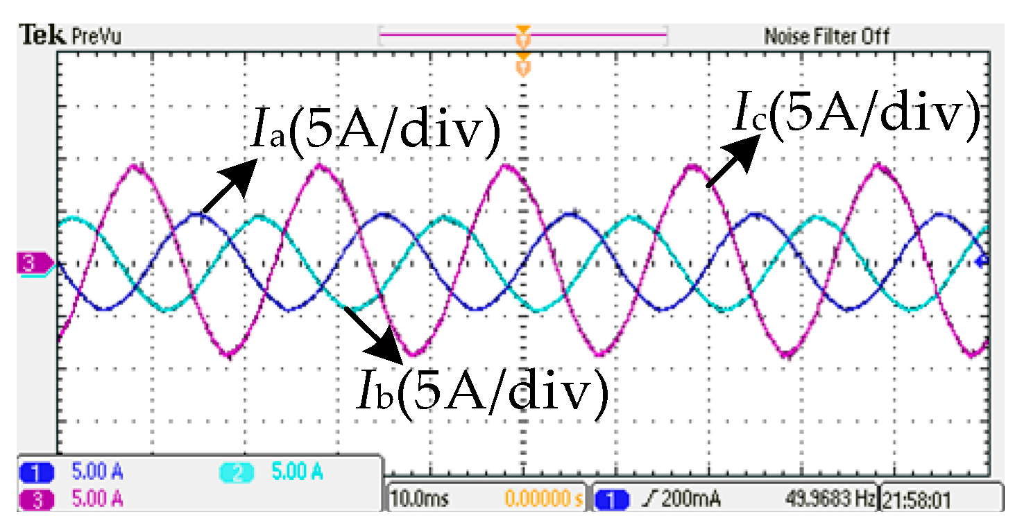
6. Experiment
7. Conclusions
- (1)
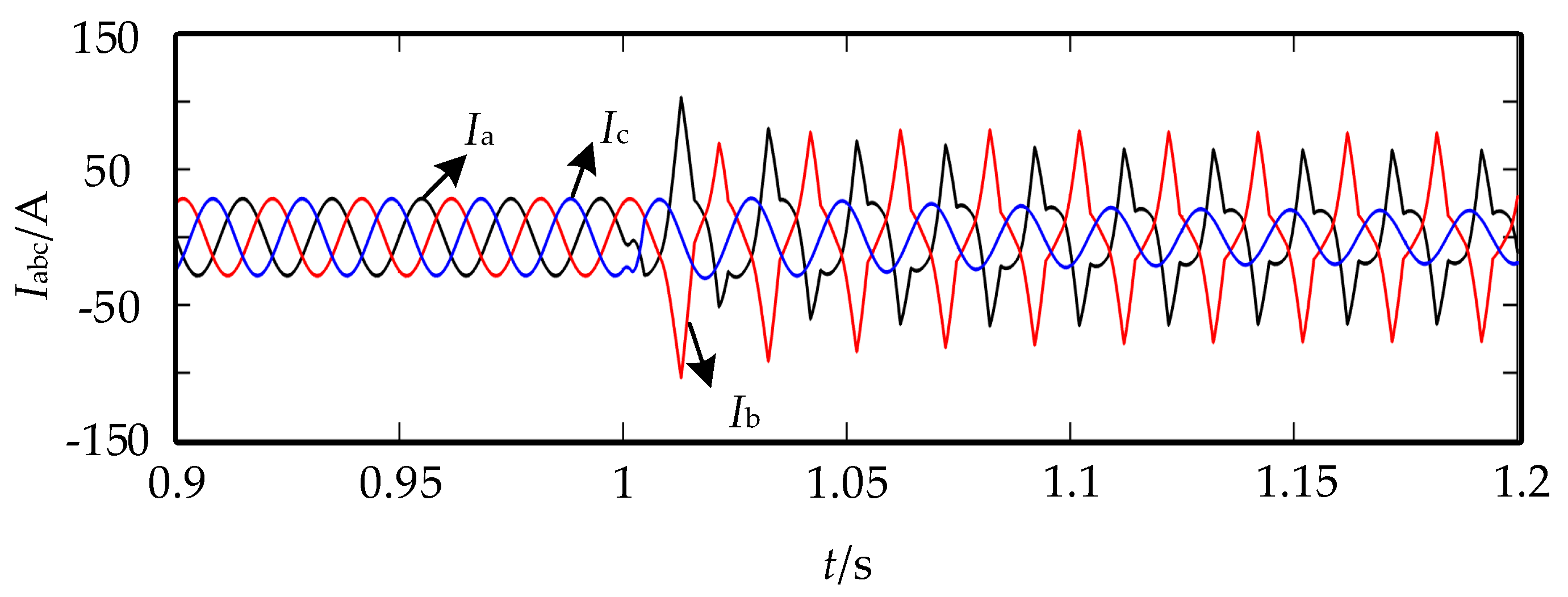
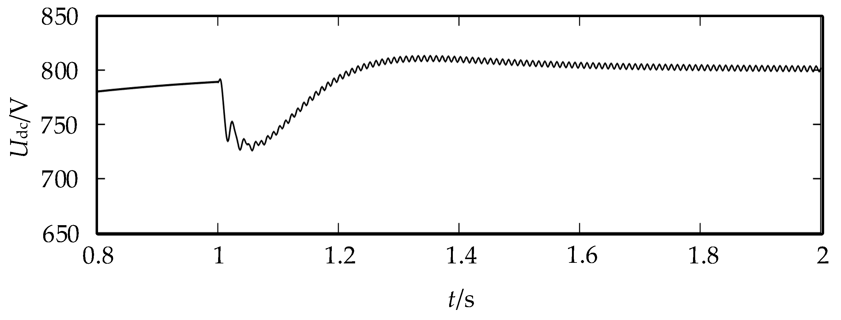
- According to the analysis of the unbalanced grid, there are double-frequency ripples in the active and reactive power transmission, which cause the three-phase current imbalance and DC voltage fluctuation.
- (2)
- The complex coefficient filter is used in the positive and negative sequence separation, which greatly reduces the complexity of the system. The model and control are more efficient.
- (3)
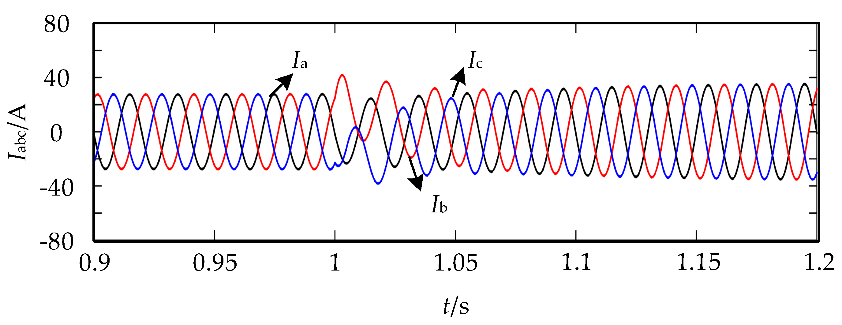
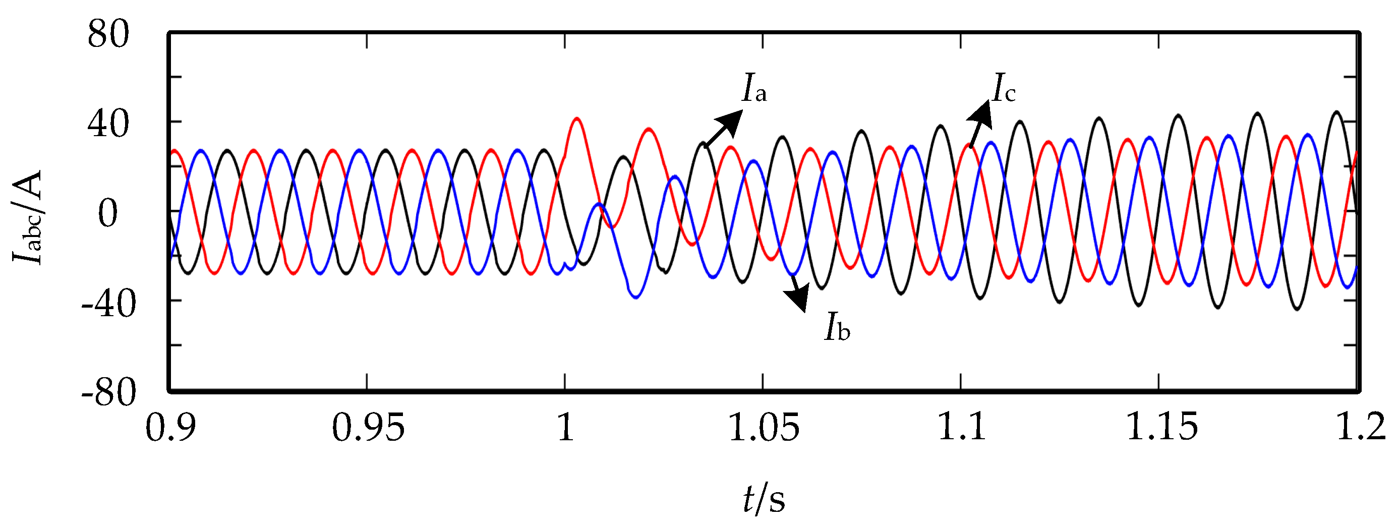
- The negative sequence current is suppressed by positive and negative sequence separation. Only the positive sequence network is taken into calculation. Besides that, a virtual impedance is introduced in the paper based on the principle of constant active power, and the ripples on the DC bus are suppressed. The control strategy can also be applied in an inverter. Only the DC voltage control needed to be replaced by the output active power control.
- (4)
- The simulation and experimental results verify the correctness and validity of the proposed control strategy. However, the voltage-unbalanced operation of VSMs in parallel still needs to be further studied.
Author Contributions
Conflicts of Interest
References
- Carrasco, J.M.; Garcia Franquelo, L.; Bialasiewicz, J.T.; Galván, E.; Portillo Guisado, R.C.; Martín Prats, M.D.; León, J.I.; Moreno-Alfonso, N. Power-Electronic Systems for the Grid Integration of Renewable Energy Sources: A Survey. IEEE Trans. Ind. Electron. 2006, 53, 1002–1016. [Google Scholar] [CrossRef] [Green Version]
- Papadaskalopoulos, D.; Pudjianto, D.; Strbac, G. Decentralized Coordination of Microgrids With Flexible Demand and Energy Storage. IEEE Trans. Sustain. Energy 2014, 5, 1406–1414. [Google Scholar] [CrossRef]
- Boroyevich, D.; Cvetković, I.; Dong, D.; Burgos, R.; Wang, F.; Lee, F. Future electronic power distribution systems a contemplative view. In Proceedings of the 2010 12th International Conference on Optimization of Electrical and Electronic Equipment, Basov, Romania, 20–22 May 2010; pp. 1369–1380. [Google Scholar]
- Zhao, Z.; Yang, P.; Guerrero, J.M.; Xu, Z.; Green, T.C. Multiple-Time-Scales Hierarchical Frequency Stability Control Strategy of Medium-Voltage Isolated Microgrid. IEEE Trans. Power Electron. 2016, 31, 5974–5991. [Google Scholar] [CrossRef]
- Jadhav, G.N.; Changan, D.D. Modelling of inverter for stability analysis of microgrid. In Proceedings of the 2016 IEEE 7th Power India International Conference (PIICON), Bikaner, India, 25–27 November 2016; pp. 1–6. [Google Scholar]
- Li, D.; Zhu, Q.; Lin, S.; Bian, X.Y. A Self-Adaptive Inertia and Damping Combination Control of VSG to Support Frequency Stability. IEEE Trans. Energy Convers. 2017, 32, 397–398. [Google Scholar] [CrossRef]
- Zhong, Q.; Nguyen, P.; Ma, Z.; Sheng, W. Self-Synchronized Synchronverters: Inverters Without a Dedicated Synchronization Unit. IEEE Trans. Power Electron. 2014, 29, 617–630. [Google Scholar] [CrossRef]
- Nguyen, C.K.; Nguyen, T.T.; Yoo, H.J.; Kim, H.M. Improving Transient Response of Power Converter in a Stand-Alone Microgrid Using Virtual Synchronous Generator. Energies 2017, 11, 27. [Google Scholar] [CrossRef]
- Edris, A.A. Proposed terms and definitions for flexible AC transmission system (FACTS). IEEE Trans. Power Deliv. 1997, 12, 1848–1853. [Google Scholar]
- Beck, H.; Hesse, R. Virtual synchronous machine. In Proceedings of the 2007 9th International Conference on Electrical Power Quality and Utilisation, Barcelona, Spain, 9–11 October 2007; pp. 1–6. [Google Scholar]
- Visscher, K.; de Haan, S.W.H. Virtual synchronous machines (VSG’s) for frequency stabilisation in future grids with a significant share of decentralized generation. In Proceedings of the CIRED Seminar 2008: SmartGrids for Distribution, Frankfurt, Germany, 23–24 June 2008; pp. 1–4. [Google Scholar]
- Zhong, Q.; Weiss, G. Synchronverters: Inverters That Mimic Synchronous Generators. IEEE Trans. Ind. Electron. 2011, 58, 1259–1267. [Google Scholar] [CrossRef]
- Alatrash, H.; Mensah, A.; Mark, E.; Amarin, R.; Enslin, J. Generator emulation controls for photovoltaic inverters. In Proceedings of the 8th International Conference on Power Electronics—ECCE Asia, Jeju, South Korea, 30 May–3 June 2011; pp. 2043–2050. [Google Scholar]
- Wang, X.; Sun, D. Multi-objective self-synchronised virtual synchronous generator in unbalanced power grid. Electron. Lett. 2018, 54, 779–781. [Google Scholar] [CrossRef]
- Zheng, T.; Chen, L.; Guo, Y.; Mei, S. Comprehensive control strategy of virtual synchronous generator under unbalanced voltage conditions. IET Gener. Transm. Distrib. 2018, 12, 1621–1630. [Google Scholar] [CrossRef]
- Cheng, P.; Nian, H. Collaborative Control of DFIG System During Network Unbalance Using Reduced-Order Generalized Integrators. IEEE Trans. Energy Convers. 2015, 30, 453–464. [Google Scholar] [CrossRef] [Green Version]
- Savaghebi, M.; Jalilian, A.; Vasquez, J.C.; Guerrero, J.M. Secondary Control Scheme for Voltage Unbalance Compensation in an Islanded Droop-Controlled Microgrid. IEEE Trans. Smart Grid 2012, 3, 797–807. [Google Scholar] [CrossRef] [Green Version]
- Zhong, Q.; Konstantopoulos, G.C.; Ren, B.; Krstic, M. Improved Synchronverters with Bounded Frequency and Voltage for Smart Grid Integration. IEEE Trans. Smart Grid 2018, 9, 786–796. [Google Scholar] [CrossRef] [Green Version]
- Liu, J.; Miura, Y.; Ise, T. Comparison of Dynamic Characteristics Between Virtual Synchronous Generator and Droop Control in Inverter-Based Distributed Generators. IEEE Trans. Power Electron. 2016, 31, 3600–3611. [Google Scholar] [CrossRef]
- Natarajan, V.; Weiss, G. Synchronverters With Better Stability Due to Virtual Inductors, Virtual Capacitors, and Anti-Windup. IEEE Trans. Ind. Electron. 2017, 64, 5994–6004. [Google Scholar] [CrossRef]
- Shintai, T.; Miura, Y.; Ise, T. Oscillation Damping of a Distributed Generator Using a Virtual Synchronous Generator. IEEE Trans. Power Deliv. 2014, 29, 668–676. [Google Scholar] [CrossRef]
- Chen, X.; Zhang, C.; Huang, Q.; Meng, J. Study on a novel control strategy of three-phase inverter under unbalanced load. In Proceedings of the 2nd IET Renewable Power Generation Conference (RPG 2013), Beijing, China, 9–11 September 2013; pp. 1–4. [Google Scholar]
- Guo, X.; Wu, W.; Chen, Z. Multiple-Complex Coefficient-Filter-Based Phase-Locked Loop and Synchronization Technique for Three-Phase Grid-Interfaced Converters in Distributed Utility Networks. IEEE Trans. Ind. Electron. 2011, 58, 1194–1204. [Google Scholar] [CrossRef]
- Dzung, P.Q.; Bao, A.N.; le Minh, P.; le Dinh, K.; Lee, H.H. The implementation of direct virtual torque control and direct power control for DFIG in wind energy system using DSpace 1103. In Proceedings of the 2011 IEEE Ninth International Conference on Power Electronics and Drive Systems, Singapore, 5–8 December 2011; pp. 884–888. [Google Scholar]


| Parameter | Value | Parameter | Value |
|---|---|---|---|
| J/(kg·m2) | 0.02 | /Var | 0 |
| D | 10 | /V | 311 |
| /(rad/s) | 100·π | /V | 800 |
| 0.1 | R/Ω | 0.3 | |
| 0.007 | L/mH | 2 |
| Parameter | Value | Parameter | Value |
|---|---|---|---|
| J/(kg·m2) | 0.00254 | /Var | 0 |
| D | 0.3 | /V | 50 |
| /(rad/s) | 100·π | /V | 160 |
| 0.01 | R/Ω | 0.3 | |
| 0.0006 | L/mH | 1 |
© 2019 by the authors. Licensee MDPI, Basel, Switzerland. This article is an open access article distributed under the terms and conditions of the Creative Commons Attribution (CC BY) license (http://creativecommons.org/licenses/by/4.0/).
Share and Cite
Miao, H.; Mei, F.; Yang, Y.; Chen, H.; Zheng, J. A Comprehensive VSM Control Strategy Designed for Unbalanced Grids. Energies 2019, 12, 1169. https://doi.org/10.3390/en12061169
Miao H, Mei F, Yang Y, Chen H, Zheng J. A Comprehensive VSM Control Strategy Designed for Unbalanced Grids. Energies. 2019; 12(6):1169. https://doi.org/10.3390/en12061169
Chicago/Turabian StyleMiao, Huiyu, Fei Mei, Yun Yang, Hongfei Chen, and Jianyong Zheng. 2019. "A Comprehensive VSM Control Strategy Designed for Unbalanced Grids" Energies 12, no. 6: 1169. https://doi.org/10.3390/en12061169