1. Introduction
Electric vehicles (EVs) have been deemed as being the future of mobility both by auto industry experts as well as major original equipment manufacturers (OEMs) globally. General Motors (GM) announced that it will release more than twenty new models by 2023; Daimler AG (Mercedes Benz parent company) announced that all of the models available will be electrified by 2022; Ford Motor Co. announced 40 electrified models by 2022; several other automakers have committed to an all-electric future [
1]. In addition to the original equipment manufacturers’ (OEMs’) commitments to an all-electric future, government agencies across the world have also set various zero emission mandates. The California Air Resource Board (CARB), Zero Emission Vehicle (ZEV) regulation has a mandate to reduce emissions level by 40% in 2030 in comparison to the level in 1990, and 80% by 2050 through regulations and ZEV credits for automakers that produce a significant number of electrified vehicles. China’s New Energy Vehicle (NEV) mandate is similar in implementation to CARB’s policies, requiring 2.5% of vehicles sold to be ZEVs by 2018 and 8% by 2025. Norway and the Netherlands have also committed to 100% EVs by 2025 and 2030, respectively. According to [
1], the EV market share is expected to grow from roughly 1% today to about 30% in Europe and around 15% in the U.S. by 2025, totaling 130 million by 2030 globally.
This exponential increase in EV adoption within a short period of time poses significant technical challenges; specifically, grid reliability issues as the current state/capacity of generation and power distribution grid is not designed to support the load profile of this number of EVs [
2,
3,
4]. Another concept that poses a significant technical challenge and could also critically affect the reliability and stability of the power grid is fast DC charging of EVs. Fast charging of EVs at 50 kW and up can lead to unsustainable load spikes on the distribution grid, especially at the peak-load periods. Therefore, fast charging will require that local energy storage/generation be present at the charging stations to meet these demands, mitigate the negative impact on the grid, and reduce operational costs during the peak-load of the grid [
5]. Studies have also shown that the degradation of existing Li-ion battery cells at DC fast charging (DCFC) is much faster than slower AC charging of less than 10 kW [
6].
For EVs to be adopted at scale, the charging infrastructure and integration with the power grid must also evolve rapidly. It is therefore imperative that these technical issues be studied and that new methods of replenishing the energy in EVs and extending the range of EVs be developed. Today, an EV of 110 km range requires 2–3 h to charge the battery from 0% to 100% state of charge (SOC) using AC charging, or 30 min to 1 h for DCFC. While fast charging shows a great deal of promise, it still poses critical technical challenges and current technologies do not offer the convenience that traditional vehicles offer in terms of replenishment of energy within 5–10 min. An optimized battery swapping station (BSS) has been presented in [
7]; however, this method is based on the assumption that consumers are willing to lease their battery as opposed to owning the battery. Several automakers and start-ups including Tesla Motors [
8] and Better Place [
9] have introduced a BSS similar to this model; however, consumer acceptance of not owning the battery and their original battery being tampered with during a swap has plagued the success of this model. This paper proposes a battery sharing station (BShS) and a battery sharing network (BShN) as a novel solution to mitigate the impact of the EVs’ scale and improve the reliability/stability of the grid. The BShS proposed in this paper is based on some of the concepts and methods that Tesla and Better Place have implemented in their BSS, but it is focused on solving the issues of consumer acceptance, standardization of battery architecture and mitigation of grid impact by EV battery charging. The BShN topology proposed is comprised of several subsystems and components such as the connected battery energy storage system (BESS) or battery, connected battery charger, renewable energy source (RES), power electronic converters, control systems, power distribution grid, and the participating EVs. The term connected in this case, refers to the internet of things (IoT) as well as grid coupling, enabling the BESS and BShN to interact and become an aggregator providing different services to the smart grid as a whole [
10]. The structural design of the BSS model is detailed in the patent in [
11], and the architecture of battery placement in the vehicle is also detailed in [
11]. A RES integrated with the BSS is reviewed in [
12], and the interaction and power exchange between different components of the BShN and the power grid is also detailed in [
12]. An optimal configuration of a BSS in terms of the number of chargers and battery packs is discussed in [
13]. Converters and charger topologies for enabling grid-to-vehicle (G2V) and vehicle-to-grid (V2G) power exchanges are discussed in detail in [
14].
This paper serves as a survey paper highlighting the current state-of-the-art battery swapping technologies and implementations available today. In addition, this paper presents a newly revamped model of battery swapping methodologies that resolves some of the issues that current battery swapping technologies face, highlighting technical challenges that face this newly proposed model and technological advancements in the near future. Section
Section 2 presents current battery swapping technologies, using the Tesla BSS as a main point of reference. The mechanical design of the swapping station system and vehicle architecture is described. Following this, the electrical design of the vehicle system, BESS, BSS, and charging system are described in detail.
Section 3 introduces a novel BShS and BShN model. The mechanical, electrical, and economic advantages over the current state-of-the-art battery swapping technology are also highlighted. Finally, the research opportunities and technical hurdles related to this novel model are presented, highlighting the important differences, the benefits, and the technological advancements needed to commercialize this proposed model.
Table 1 is a list of acronyms and abbreviations with definitions of technical terminology used in this paper.
2. Overview of Current Battery Swapping Station Technology
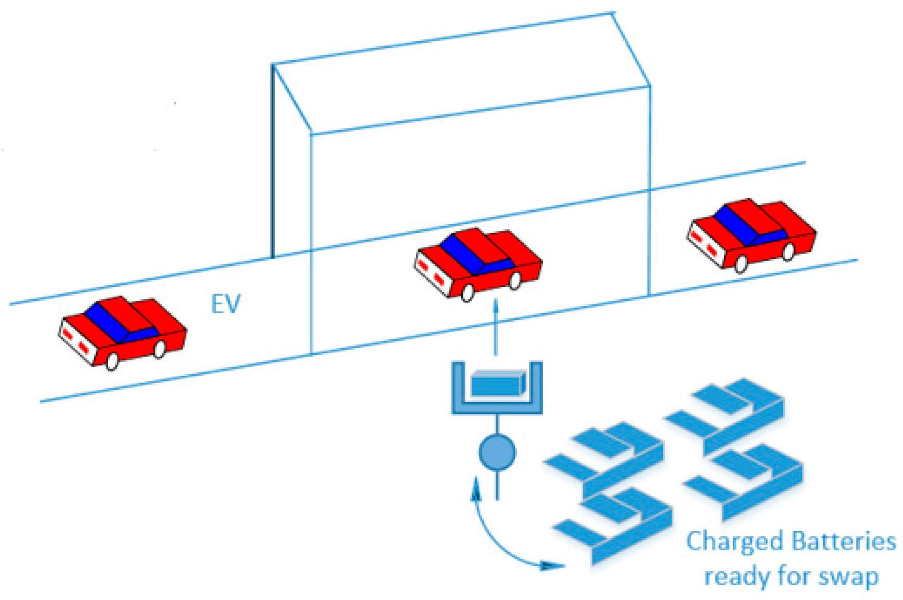
In this section, a general overview of the main components of a BSS is illustrated, with the Tesla BSS as a case study. The BSS consists of mechanical and structural components as well as electrical components.
Figure 1 is a conceptual description of the BSS.
2.1. Structural Design of a BSS
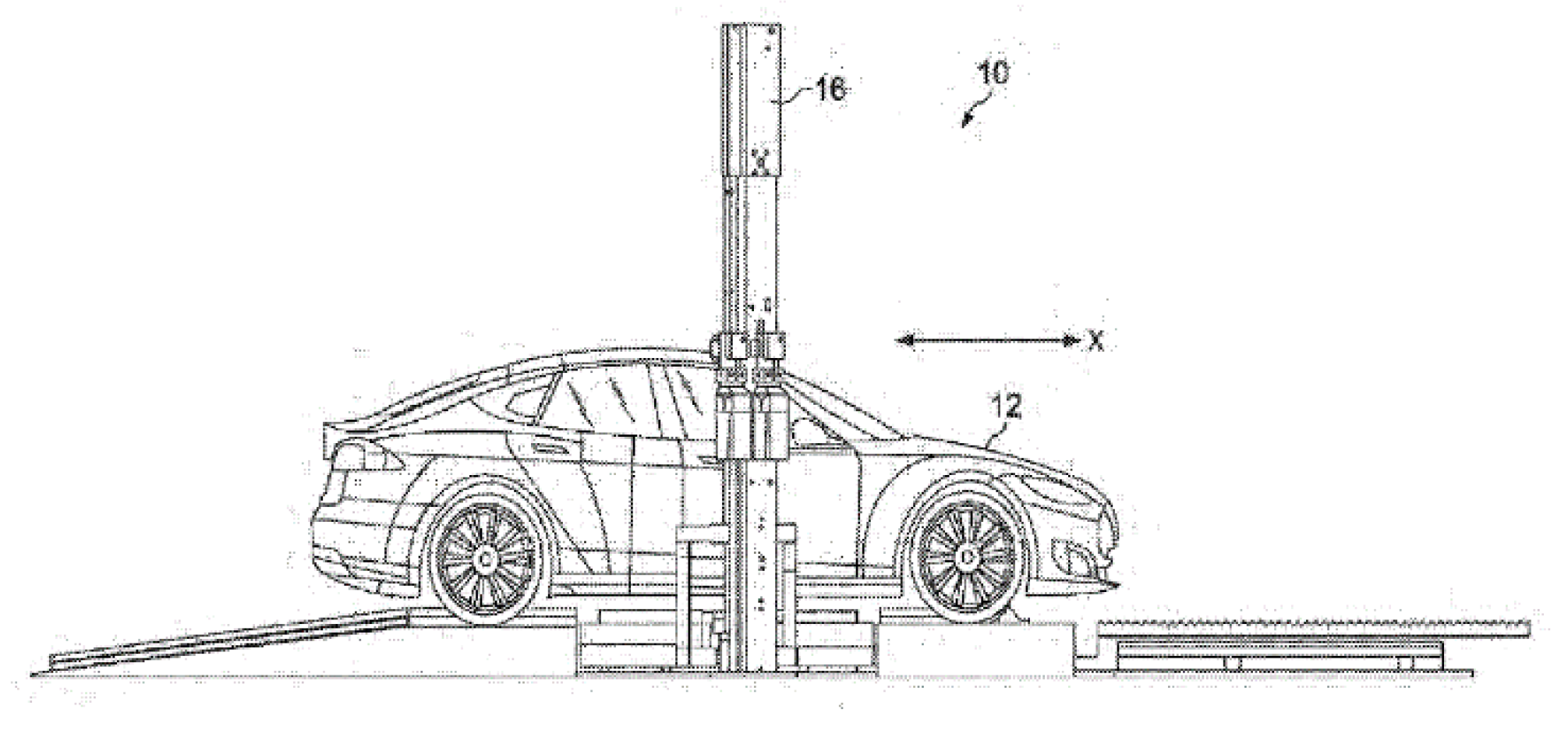
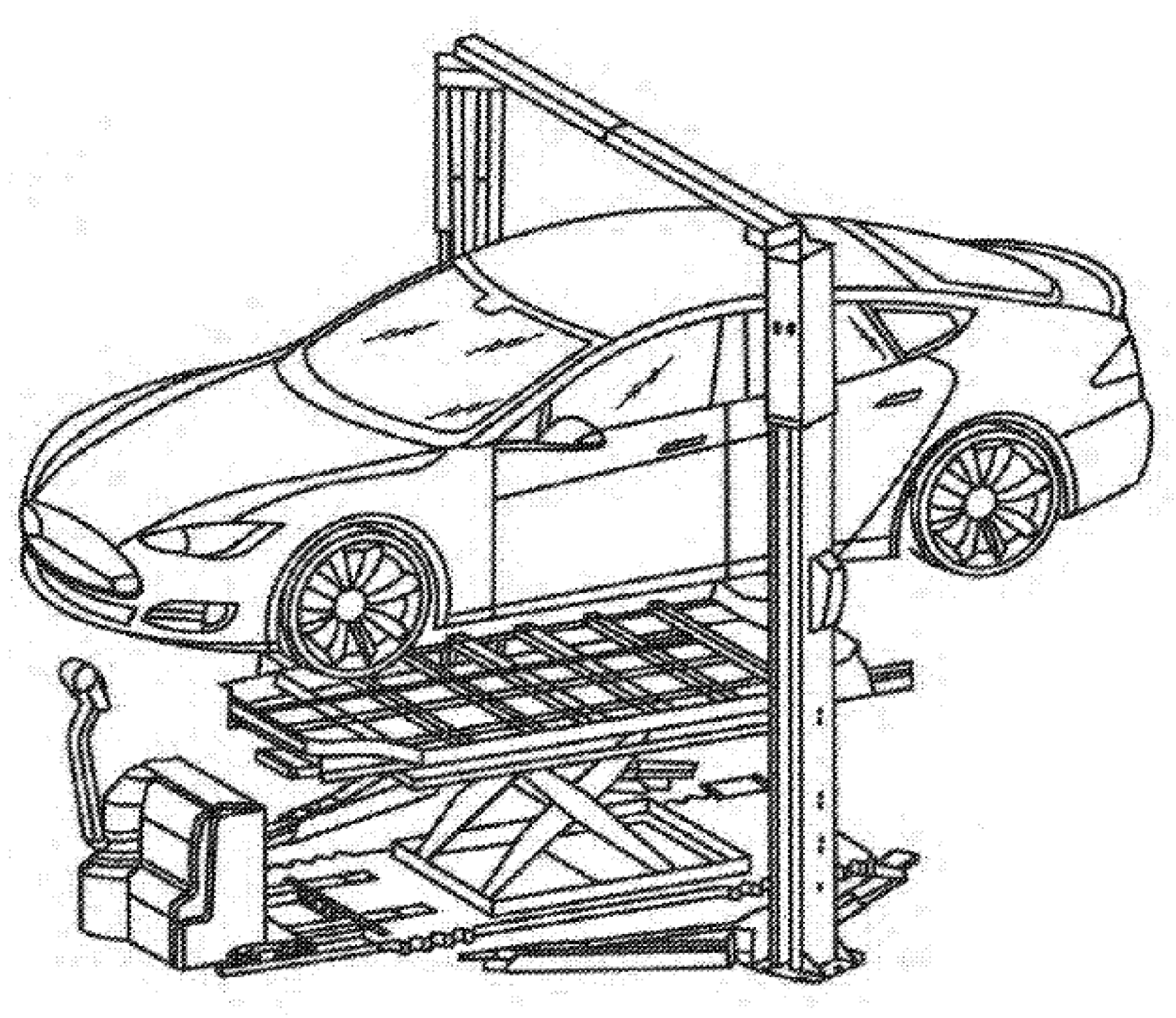
The Tesla BSS shown in
Figure 2 includes a vehicle platform, a vehicle lift, battery lifts, vehicle alignment equipment rollers, electrical connection alignments, battery conveyor shuttles, and battery storage racks and rails.
Figure 2 shows an EV that has arrived at a BSS and is ready to be engaged in a swap.
2.2. Mechanical Operation of BSS
A compatible EV with a battery architecture designed for the BSS is needed in order to participate in battery swapping. In addition, prior to arriving at the BSS, the EV must schedule the battery swap ahead of time to confirm that a battery pack will be available for swap. When the EV arrives at the BSS, it climbs up a slight ramp as shown in
Figure 2 and this constitutes the beginning of the swap.
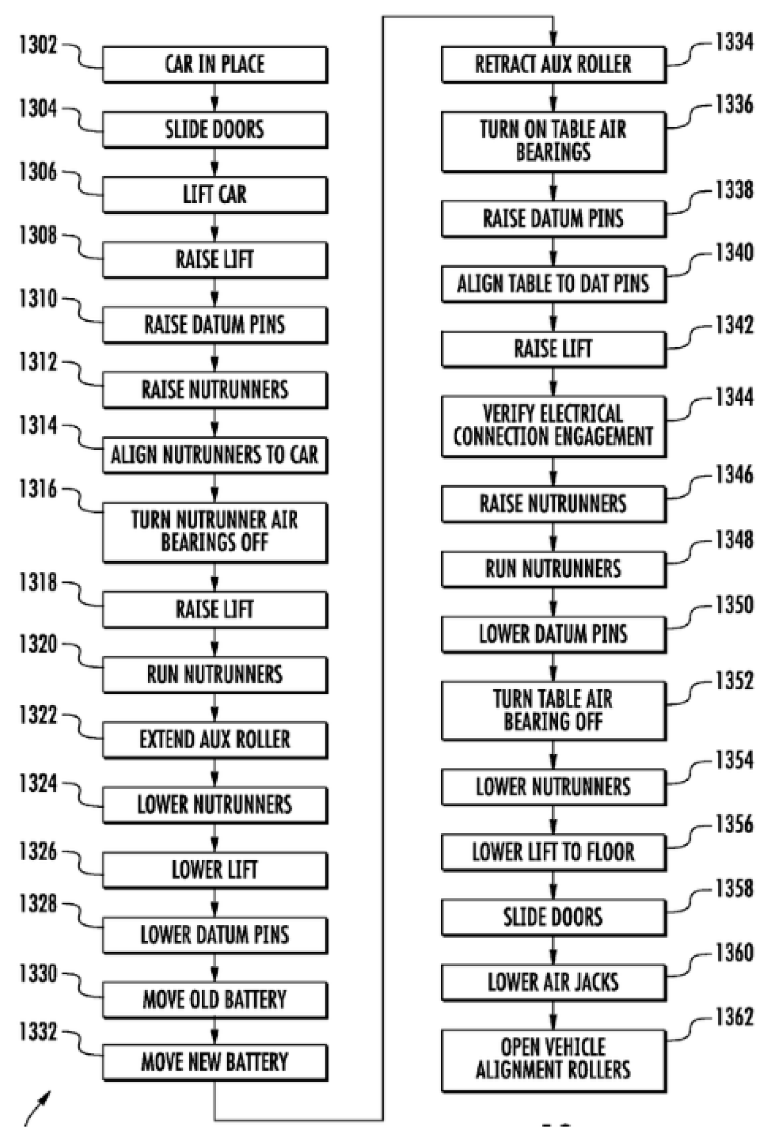
Figure 3 is the flow of operation of the battery swap [
15].
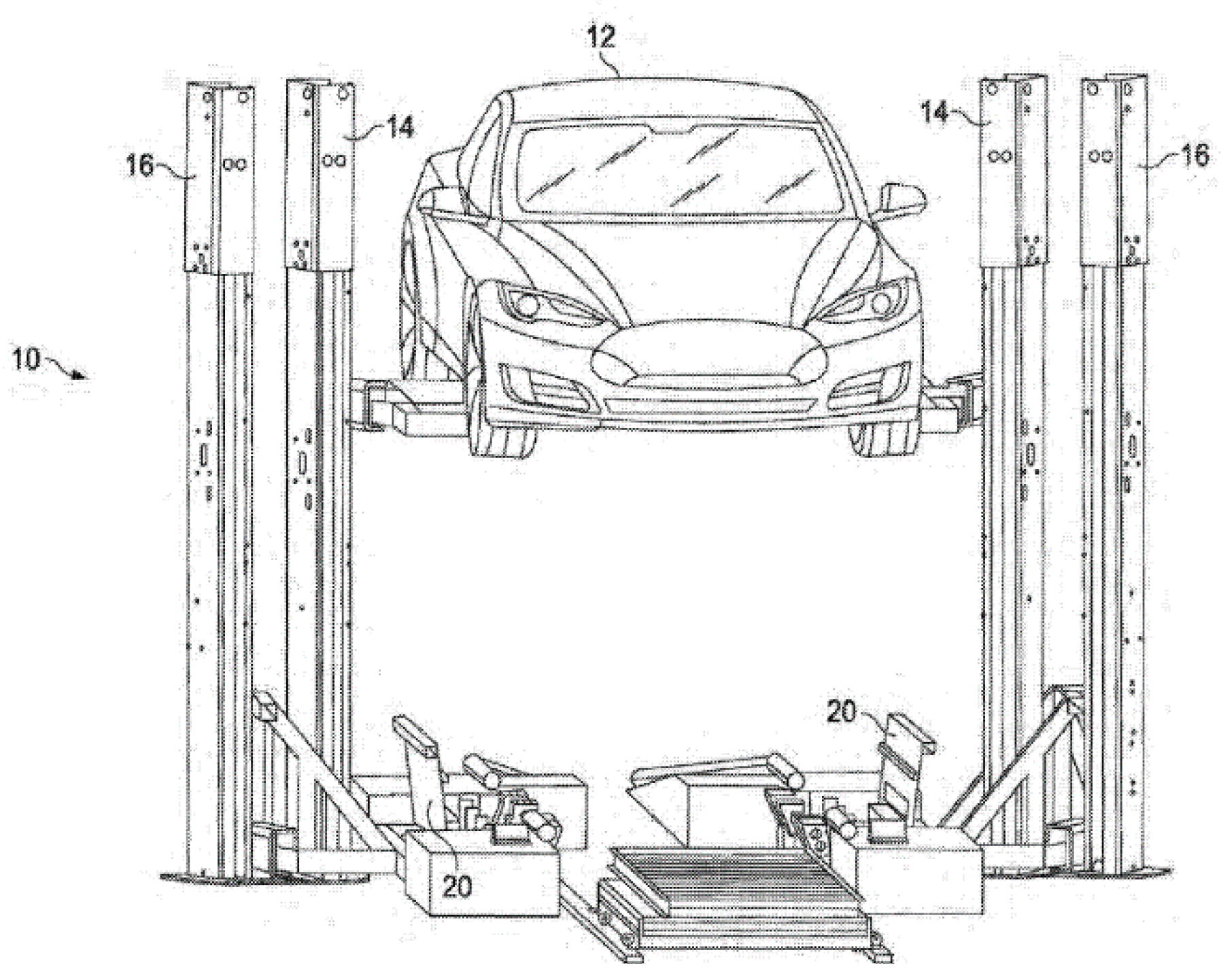
The vehicle is positioned correctly in the X direction and the vehicle power is turned off for safety. Next, the vehicle is raised with the vehicle lift as shown in
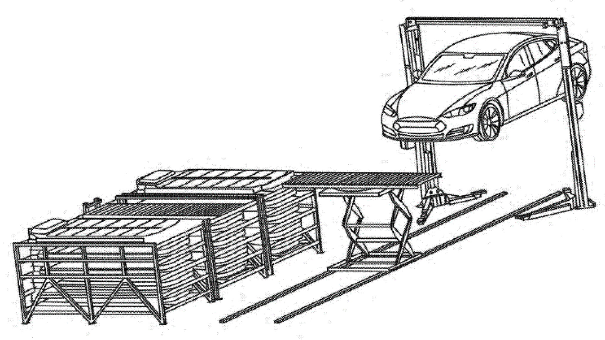
Figure 4, where the lift boards, in this case, engage the jack pads on the vehicle to provide support. Once the vehicle is lifted, horizontal doors underneath the vehicle are opened to allow access to the battery that sits underneath the vehicle. Next, the battery lift is raised until it touches the underside of the battery pack in order to support it for removal. Once the lift is correctly placed underneath the battery securely, the fastener removal can begin. Next, a battery conveyor shuttle is brought underneath the battery lift as shown in
Figure 5. The used battery, now on the battery lift, is lowered onto the battery conveyor shuttle; the used/depleted battery is replaced by a fresh one from the battery rack shown in
Figure 6. The fresh battery is then raised up underneath the vehicle. The battery is again positioned and secured by the battery lifts, the fasteners are engaged and doors closed. Now, the vehicle is ready to be lowered and powered back on to get back on the road with a fully replenished battery pack.
2.3. Electrical Design of BSS
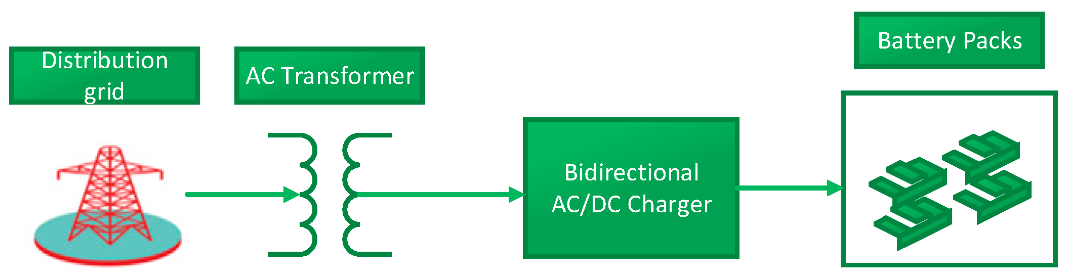
In today’s implementation, the BSS is heavily dependent on the distribution grid and represents new high power consumption loads for the distribution system operators. The electrical components of the BSS are mainly composed of a distribution transformer, AC/DC chargers, battery packs, and a battery energy control module (BECM).
Figure 7 is a block diagram of the electrical relationship between the components of the BSS.
The distribution grid provides the AC power at the distribution voltage level, and because of the high power demand of the BSS, this voltage level will be between 33 kV and 11 kV. Charging power levels for EV battery packs range from Level 1 charging at 120 V/15 A single-phase; Level 2 Charging at 240 V (up to 80 A, 19.2 kW); and Level 3 Charging at 50 kW and up [
15]. Depending on the size of the BSS and the voltage level available at the distribution grid, different charging modes can be implemented.
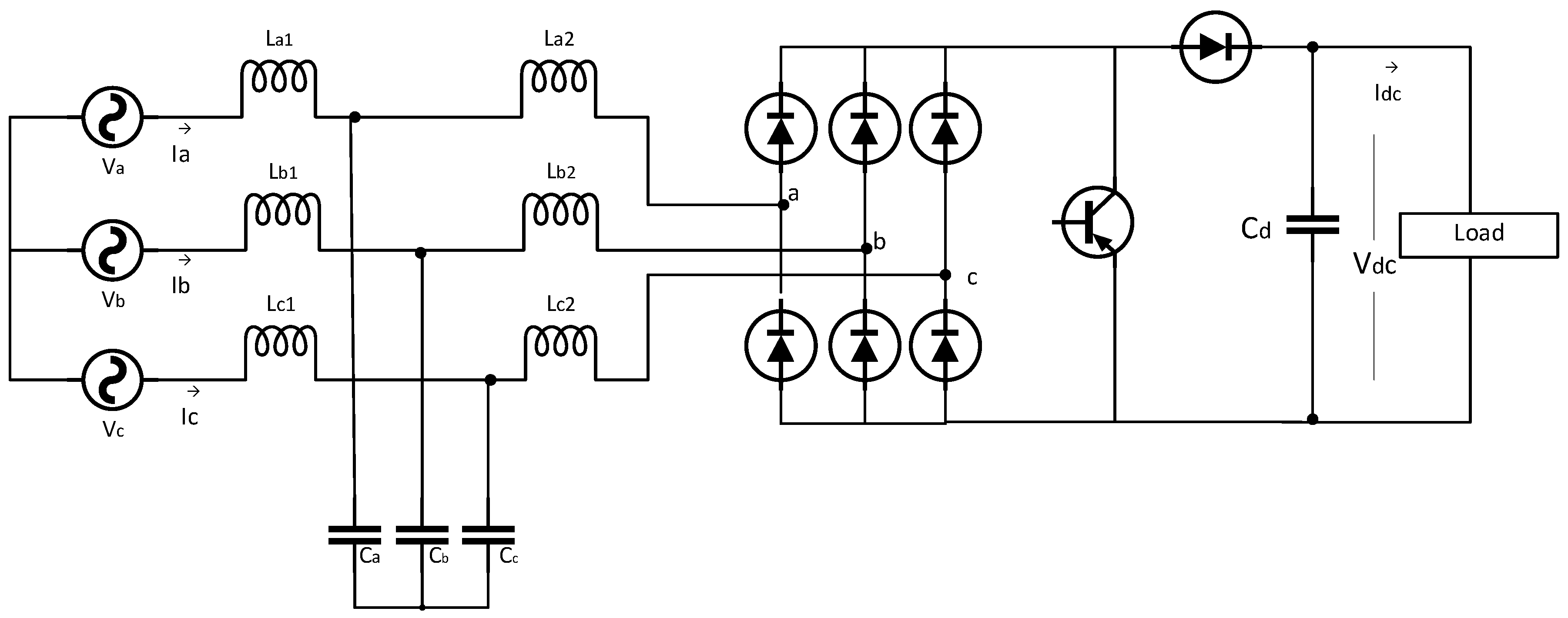
Charging profiles determine the rating of the AC/DC charger. In our case study, a unidirectional AC/DC charger is implemented which is connected to the AC transformer and converts the AC power to DC power to charge the batteries directly.
Figure 8 is a single switch unidirectional boost converter with passive filtering for the BSS AC/DC charger topology. The number of unidirectional buck converters, control strategies, and component selections are discussed in detail in [
16].
2.4. Battery Energy Management and Thermal Design of BSS
Battery temperature is a primary factor in regards to performance and life cycle of an EV battery [
17]. Li-ion batteries should ideally operate between 25 °C and 40 °C for optimal life and performance. Using air as a heat transfer medium is a cheap and simple method for battery cooling; however, it is very inefficient in comparison to liquid cooling. Some of the limiting factors of air cooling in EVs are limited flow rate of cooling air, noise, inhomogeneous temperature distribution within batteries, dependence on vehicle cabin air temperature, and safety concerns due to the emission of toxic gases from the battery packs [
17].
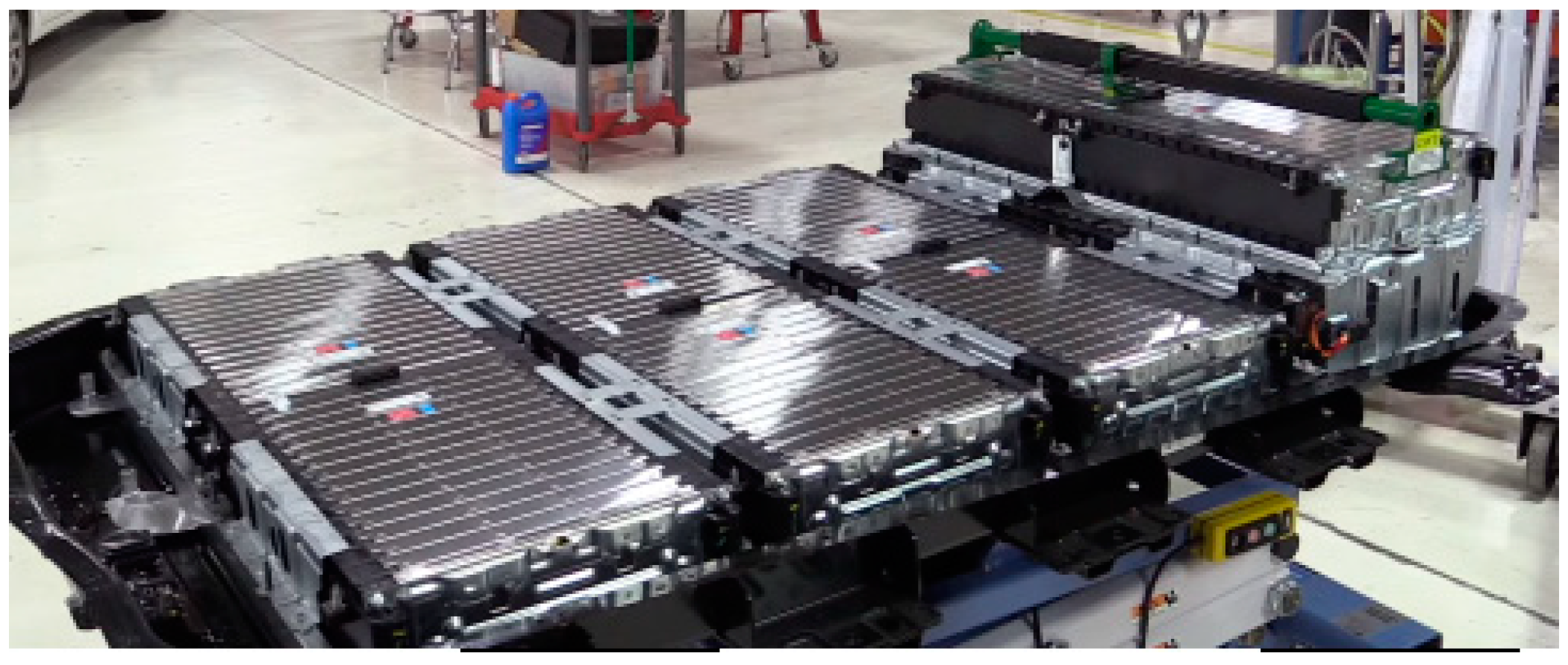
Liquid thermal management is a much more efficient method of cooling Li-ion batteries; however, it is more costly and complex to implement. In liquid cooling, a cooling plate can be placed on the surface of the battery and a liquid cooling or heating refrigerant can be passed through tubes onto the plate to draw heat from the battery cells.
Figure 9 is a photo of an EV battery for the Chevy Bolt, which uses this method of cooling for thermal management of the battery.
In the BSS, some of the constraints of air-cooling in the EV are not present, as the batteries can be stored in an area where the temperature of the room or storage facility is not a concern. Since the BSS is also designed to be fully automated, some of the safety concerns with air-cooling in EVs are also not present in the BSS. The battery storage chamber is also heavily insulated to increase the efficiency of air-cooling and achieve a more uniform temperature distribution across the cells.
In the BSS, a combination of air and liquid cooling can be implemented to maximize efficiency and cost. The BECM is critical in the BSS as it is constantly responsible for monitoring the charging power of battery cells, voltage across each cell, as well as the temperature of each cell. The BECM is also responsible for balancing the voltage and charging across all of the cells of each battery pack in the BSS and maintain the safe temperature range of battery cells.
2.5. Battery Swapping System Challenges and Opportunities
A major hindrance to the adoption of EVs is the high cost of ownership, which is directly linked to the cost of the onboard battery. In modern EVs today, the cost of the battery is 25−50% of the entire cost of the vehicle [
1]. BSS have a unique opportunity to relieve some of the pain points that EV adoption faces. In an ideal BSS system, a third party will have the ownership of the battery and is responsible for replacing the depleted batteries of its partners or customers with fully charged ones, as well as monitoring the health of the batteries and decommissioning/repurposing the batteries once the life is no longer suitable for the e-mobility use case. This leasing/pay-as-you-go model could be particularly attractive for fleet use cases such as ride-sharing and package delivery services (who drive a significant number of miles daily and cannot afford a lot of downtime). In addition to significantly reduced waiting times compared to DCFC, BSS can provide two additional benefits to the power grid in terms of reliability. The behavior of EV owners in terms of charging is stochastic and unpredictable, which could lead to unsustainable penetration of the grid as EV adoption increases in scale. BSS can allow for controlled/scheduled charging of depleted batteries, postponing charging of batteries to off-peak hours thereby acting as a large flexible load from the grid’s perspective. BSS can also act as energy storage aggregators with enough storage capacity to participate in electrical energy markets, providing services to the system such as voltage support, regulation reserves, and energy arbitrage.
However, the roadblocks that surround BSS still remain: Standardization of EV battery packs; consumer acceptance of BSS model; reliable estimation of battery state-of-health. Another important factor to consider is the distribution and cost of BSS and charging infrastructure. Standardization of EV battery packs, while necessary, appears to be very unlikely; this is largely due to the fact that the competitive edge for EV OEMs are closely aligned with their underlying proprietary battery technology. The battery pack is also a core piece of the car’s strength, stability, and safety at design time, making it increasingly difficult for OEM’s to share a similar battery architecture across the board. Individual OEMs, however, can share battery architectures across several models as is seen in the battery architecture design of the Tesla Model S and Model X [
8]. A similar battery architecture across models and brands of individual OEMs will foster the feasibility of BSS models similar to OEM specific service dealerships.
The concerns of consumers with regards to the BSS model are related to both the consumer anxiety of not owning the battery at the time of purchase of the EV as in the business of Better Place [
9] or the EV owner receiving a battery which he/she has no guarantee of the current state of health and degradation of the swapped battery as in the case of the Tesla BSS [
9]. The warranty issues surrounding the replaced battery pack caused a low participation by EV owners for Tesla’s BSS pilot launch at the Harris Ranch facility in California [
9].
Accurate SOC and SOH estimation of the Li-ion battery to ensure its safe operation and its capabilities in BSS applications is critical. Accurate estimation of Li-ion battery SOH and cycle life are typically empirical in nature, requiring induced aging tests conducted under several conditions of Li-ion batteries specific to the battery chemistry. As EVs have evolved, several approaches have been proposed in the literature to predict the SOC and SOH of the EV battery both onboard as well as offline [
18,
19,
20,
21,
22]. An accurate offline SOC and SOH estimation plays a significant role in the technical feasibility of BSS models as batteries are constantly moved around; the importance of the online estimation of battery health and capacity is highlighted in the next section.
Another important modeling challenge is the optimized distribution and sizing of BSS across the EV network. Modeling of BSS penetration and interaction with the grid both as a flexible load and as an energy storage market participant or aggregator is also of utmost importance. In [
23], a modified differential evolution algorithm is adopted to solve the problem of geo-distribution and scale of BSS for optimal cost–benefit and safe operation. The proposed method is also verified on the IEEE 15-bus and 43-bus radial distribution system. A proposed model aimed at scheduling battery charging with respect to the availability of battery chargers, and hourly demand for battery swapping is presented in [
24]. The participation of the BSS in the electricity market plays an important role in the economic viability of the BSS; a BSS model based on the short-term battery management is presented in [
25] and includes the mathematical formulation of the problem as well as the market strategy.
3. Advanced Battery Sharing Station and Battery Sharing Network
Current state-of-the-art implementations of battery swapping stations have been discussed, with the Tesla BSS that was launched in 2014 as a case study. However, this current implementation possesses several technical and economic challenges. Such challenges are the nonstandard battery interface across EV manufacturers and consumer acceptance of not owning their battery or their original battery being tampered with and replaced with a lower performance battery during a swap. Another critical challenge is the heavy dependency of the BSS on the distribution grid, and the high power demand of the BSS, which could have a negative impact on the grid during peak loading periods. In this section, a new design of the EV battery architecture is proposed to achieve a common standardized modular battery interface across EV manufacturers. In addition, a RES and a bidirectional AC/DC charging interface is introduced, which allows the BSS to become a service utility that supports the grid in terms of distributed generation and storage. Finally, in the next section, some technological advancements and research opportunities are presented, which could stem from this proposed BSS model.
3.1. Battery Architecture Structural Re-Design
Traditional EVs contain a large BESS as the source of power for the vehicle propulsion system. The battery pack is typically 50−100 kWh in capacity, costing thousands of dollars and has an adverse effect on the weight of the vehicle. However, studies have shown that the typical daily drive cycle for the average consumer is approximately 40 miles (64 km) for 95% of their drive cycles, corresponding to about 15 kWh capacity requirement for daily driving. A connected universal battery pack (UBP), referred to in this paper as a boost pack, is proposed as an alternative to the traditional battery pack. It has a highly reduced weight and can charge more quickly than conventional packs, it also has the capability of being able to be combined with additional boost packs when a longer range is necessary. In addition, the battery packs are also connected through IoT to constantly manage the battery state of health (SOH), state of charge (SOC), and broadcast its various data points with the BShS and the BShN.
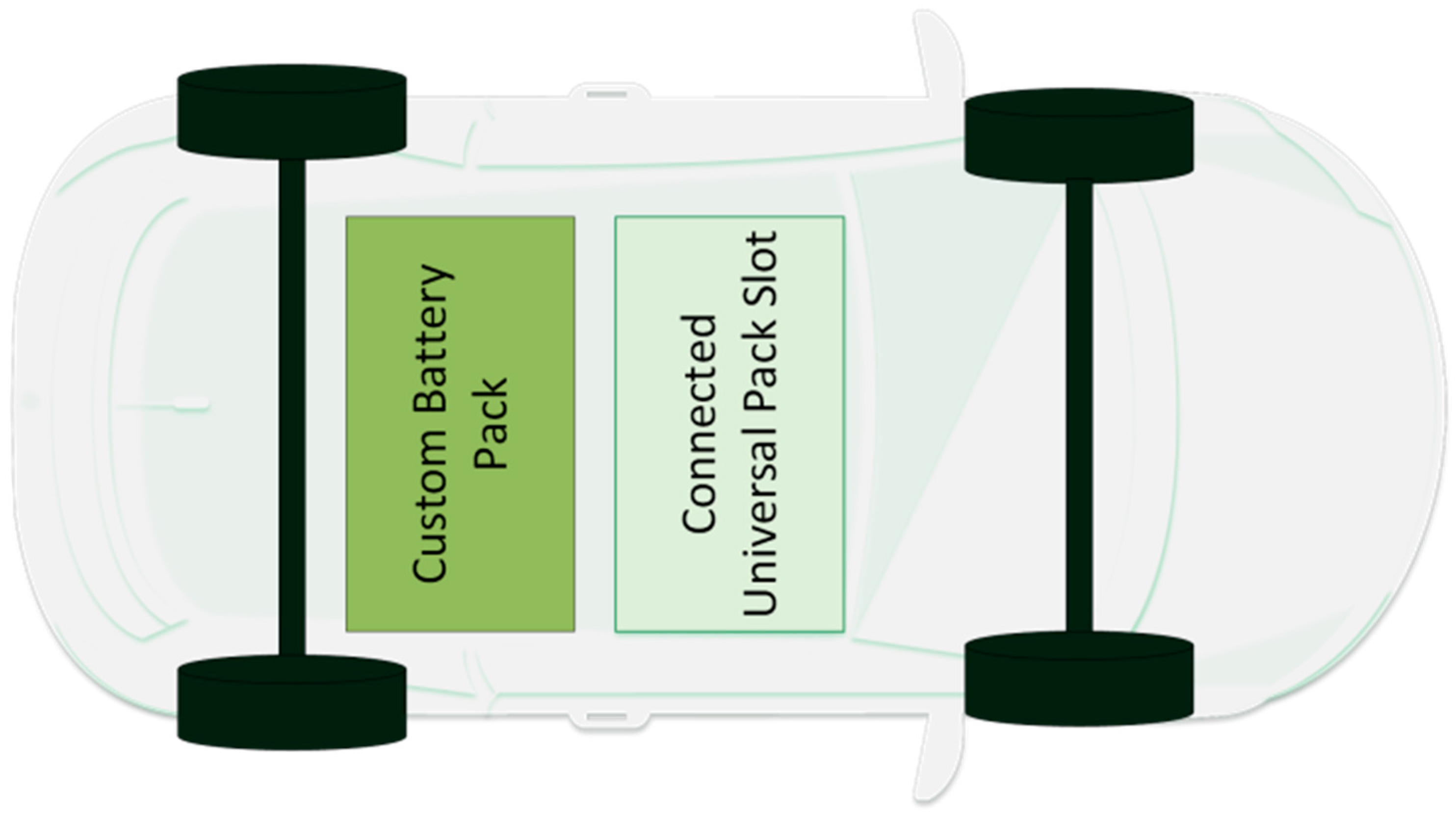
Figure 10 is a diagram of the new battery placement architecture proposed inside of an EV. As seen in the description, the OEM has the option to design a custom battery pack that is permanently part of the vehicle, enough to cover the daily driving needs of the EV owners, provided that they are able to charge at home daily. This greatly reduces the load demand that the EV owner puts on the grid as the battery can be charged over a long stretch of time at night when load is minimal and the electricity is cheaper. The UBP slot in the vehicle is designed to provide the EV owner flexibility to participate in the BShN. The UBP and slot are standard and capable of providing a range of 100 miles (161 km) or more and available on demand at a BShS discussed next.
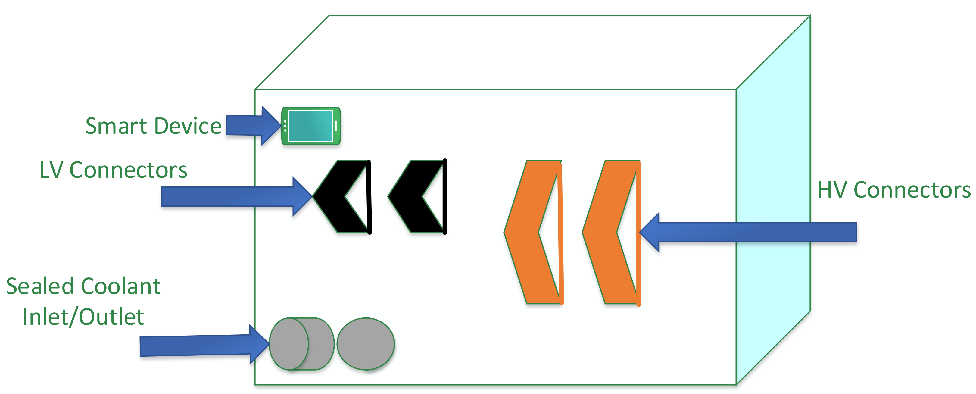
Figure 11 is a description of the connected UBP. The UBP is modular and consists of high voltage (HV) connectors, low voltage (LV) connectors, tube connectors for thermal management, and an embedded device for autonomous onboard diagnostics of the battery pack.
The specifications of the UBP proposed is detailed below. Its controls and electrical and mechanical connections are designed with the intent of providing propulsion power to the vehicle as well as being able to be connected to the grid through the BShN. The base UBP and EV design specifications are as follows:
Universal Battery Specs
Capacity = 30 kWh (110 MJ)
Battery Mass = 480 lb (220 kg)
Charge time = 4.5 h at 220 V
EV with Universal Battery Specs
Energy Cost = 218 Wh/mi (252 Wh/mi for Chevy Bolt),
Energy Cost = 137 MPGe
Car Weight = 3083 lb (1396 kg)
Volume = 142.5 L
Energy Usage = 0.2 kWh/m
Range = 137 miles (220 km)
Cost = $145/kWh, $4350
Power Rating = 150 hp (111 kW)
0–60 m/h = 9 s
3.2. Battery Sharing Station and Battery Sharing Network
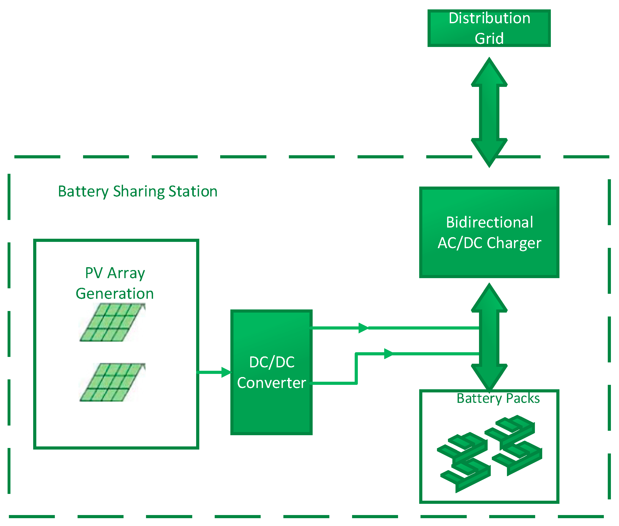
The BSS discussed in the first section of this paper is modified to include an RES. A PV system is integrated with the BSS. In addition, a bidirectional AC/DC converter topology discussed in [
15] is implemented allowing the battery packs in the BSS to provide V2G services to the smart grid.
Figure 12 is a block diagram description of the system structure of the proposed BShS. The BShS is also a part of a network of BShS, referred to as a BShN, linked together through the IoT and telecommunication interfaces, communicating to optimize the cost of charging, reduce the waiting time for battery swaps by forecasting battery swaps and share the UBPs amongst each other through participating EVs and EV customers. EV owners can participate in the BShN and transport battery packs from the BShS where they are located to the BShS where they are needed for incentives such as free battery swaps or payment. The UBPs are transported from BShS to BShS through the embedded UBP slot on optimized routes convenient for EV owners. This reduces, or completely eliminates, the need for dedicated vehicles for transportation of EV battery packs from station to station.
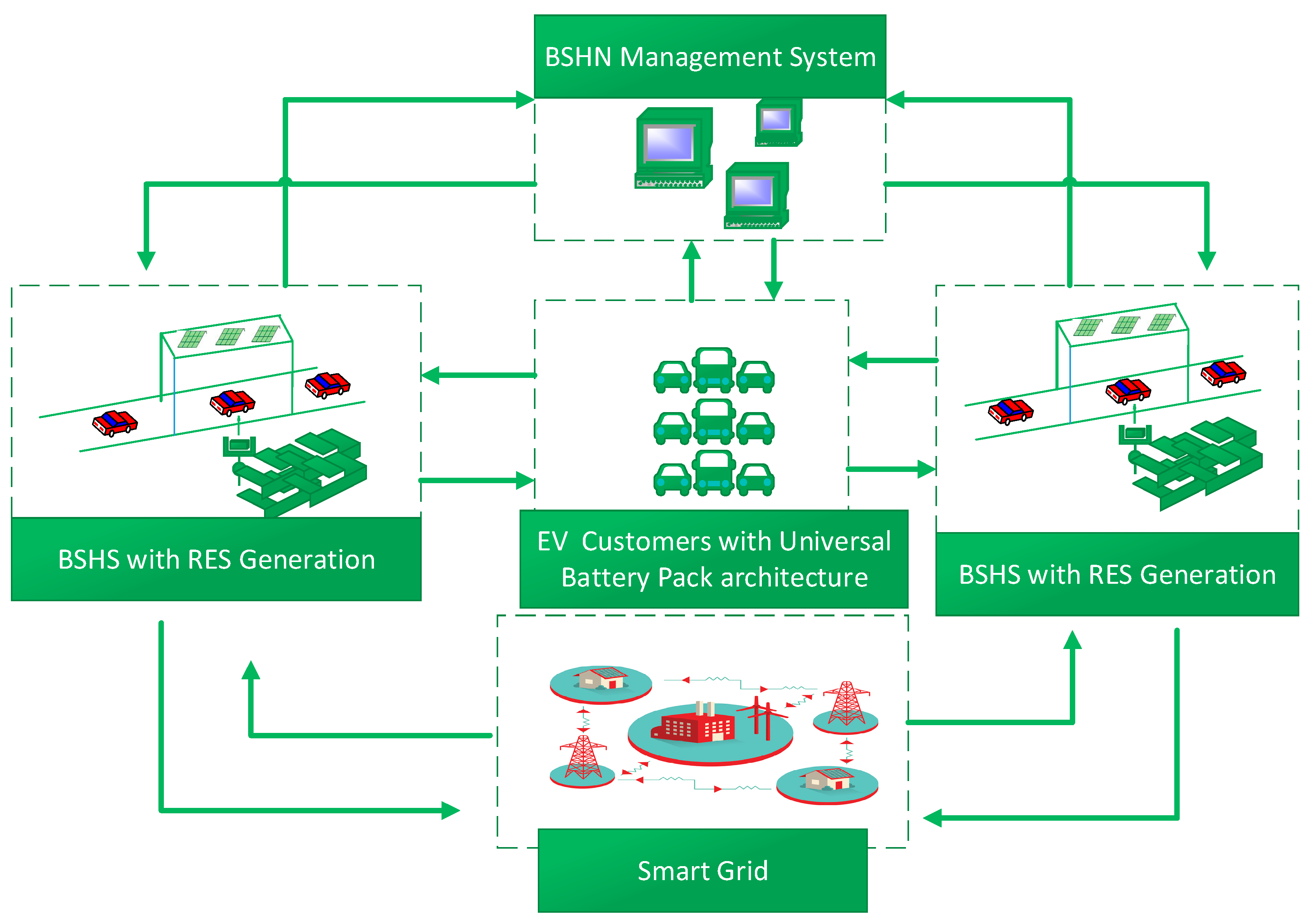
Figure 13 is a conceptual illustration of the BShN. The BShN consists of several functional subsystems; the communication between these systems is handled by the BShN Management System. This system coordinates the bidirectional flow of power between the BShS and the smart grid which is designed for distributed generation and bidirectional power flow. It also coordinates the optimized routing of boost packs in the BShN through the EVs that participate in the network. In addition, the BShN management system controls the scheduling of battery swaps as well as forecasting of future swaps and grid loading. The BShN management system in this proposed scheme becomes a grid utility, providing services to the grid, such as peak shaving and load balancing, and serves as a reserve for the grid during contingency situations. The proposed BShN consists of several technical hurdles that need to be addressed in order to become commercially available. Some of these technical hurdles are presented as research opportunities in the following section.
4. Research Opportunities
4.1. Structural Design of Modular Battery EV
A structural design for EVs that is compatible with a UBP needs to be further investigated. The positioning of the battery slot for ease of access during a swap is critical to determining how fast and convenient a swap/boost will take place. Consumers are more likely to switch to EVs if replenishment of energy is under 5–10 min. Furthermore, electrical connectors and cables capable of withstanding thousands of swaps safely without significant wear need to be developed.
4.2. Thermal Management of Batteries during Normal Mode and Boost Mode
Thermal management systems of EVs today are typically liquid based and tightly coupled with the EV battery. In order for modular battery packs to be hot-swapped from an EV, the thermal management design is critical. Currently, before a swap is done, all of the thermal fluid in the battery pack must be drained completely to avoid spillage. Furthermore, when a new boost pack is added, it must integrate seamlessly with the existing thermal management architecture of the EV. Similarly, when the battery pack is taken off of an EV and placed at a BShS, it must be integrated seamlessly with the BShS thermal management system. A cost-effective and somewhat standardized method of thermal management such as ambient air-cooling or other forms of gases must be researched in order for the UBP to become practical.
4.3. Electrical Design of Power Electronic Converters and Control
A major benefit of the modular battery pack design for the EV is the reduction in the weight which increases the overall efficiency of the EV. However, with the addition of boost packs, additional circuitry must be added to the vehicle in order to balance the power between both battery packs during boost mode. This additional circuitry adds additional cost in terms of weight to the vehicle that is not needed during normal operating modes; therefore, it is necessary to investigate and come up with multidirectional, high power density, low-cost power electronic converter schemes that accommodate for different modes of operation of the EV.
4.4. Electrical Power Management of EV to Include Ultracapacitor during Heavy Loads
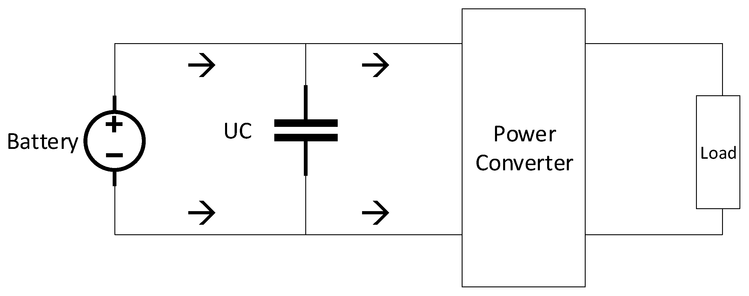
A reduced capacity in EVs to accommodate for the boost pack in the EV also implies reduced maximum power. This is sometimes undesirable during acceleration from a dead stop or at higher driving speeds. Therefore, a high power density, low-energy density source such as a supercapacitor or ultracapacitor needs to be integrated with the main battery to provide additional power to the wheels during short heavy load demand periods.
Figure 14 from [
17] is a circuit diagram illustrating the addition of a supercapacitor with a battery for additional power during heavy load. During the lower or normal loading periods, the main battery quickly recharges the ultra-capacitor. A practical implementation of such a scheme is a needed topic of research for the advancement of smaller modular battery packs with high performance.
4.5. Further Topics
Aside from the topics discussed above, other topics where research is needed in the area of battery swapping as a practical solution to EV adoption include the following:
Smart charging of EV batteries at BShS
Standardized IoT/telecommunication schemes for BShN components and interaction with the grid
Automated scheduling and billing system for BShN
Forecasting of battery swaps and storage availability from the BShS
Optimization of routes for battery delivery in the BShN
Cost–benefit analysis of the BShN model over traditional BShS and DCFC.


