Article

DG System Using PFNN Controllers for Improving Islanding Detection and Power Control †

Department of Electrical and Electronic Engineering, Chung Cheng Institute of Technology, National Defense University, Taoyuan 335, Taiwan
*
Author to whom correspondence should be addressed.
Presented at the Fourth IEEE International Symposium on Computer, Consumer and Control, 2018 (IS3C 2018), Taichung, Taiwan, 6–8 December 2018.
Energies 2019, 12(3), 506; https://doi.org/10.3390/en12030506
Submission received: 8 January 2019 / Revised: 25 January 2019 / Accepted: 31 January 2019 / Published: 5 February 2019

Abstract

:
In this study, an intelligent controlled distributed generator (DG) system is proposed for tracking control and islanding detection. First, a DC/AC inverter with DC power supply is adopted to emulate a DG system and control the active and reactive power outputs. Moreover, in order to comply with the standard for interconnection with the power grid, a novel active islanding detection method is proposed for the inverter-based DG system. In the proposed active islanding detection method, a perturbation signal is designed to inject into the d-axis current of the DG system which causes the frequency at the terminal of the RLC load to deviate when the power grid breaks down. The feasibility of the proposed active islanding detection method is verified according to the UL 1741 test configuration. Furthermore, in order to improve the tracking control of the active and reactive powers of the inverter-based DG system, and to effectively reduce the detection time of islanding phenomenon, two probabilistic fuzzy neural network (PFNN) controllers are adopted to take the place of the conventional proportional-integral (PI) controllers. In addition, the network structure and the online learning algorithm of the adopted PFNN are presented in details. Finally, some experimental results of the proposed active islanding detection method using PFNN controllers are proposed to validate the effectiveness and feasibility of the tracking control and islanding detection.

1. Introduction

Nowadays, due to the growing awareness about environmental concerns and the limited supply of fossil fuels, renewable energy sources (RES) such as wind turbine, biomass, photovoltaic, fuel cell, etc., have been gaining wide attention in power system [1,2]. Moreover, in the past decades, the manufacturing technology of distributed generators (DGs) based on RES has also matured. Thus, DG systems have become part of daily life. Owing to the increasing penetration of DG systems, the power system has become more complex and this raises several concerns. The most important issue of the DG systems connected to the power grid is the islanding phenomenon [3,4]. Islanding occurs when DG systems and loads are disconnected from the power grid but continue to dispatch the generated power energy to the loads [5,6]. In other words, when the load power and the generated power of the DG systems are balanced, i.e., the load power is fully supplied by DG systems, the islanding phenomenon occurs. Meanwhile, if the power grid breaks down, the frequency and voltage disturbances of DG systems can’t be detected according to the IEEE 1547 or UL 1741 standard [7,8]. The islanding phenomenon will endanger the power system and result in poor power quality and personnel safety hazards [9]. Hence, in practice, the islanding phenomenon is an intolerable situation and isn’t allowable in the power system. Moreover, according to the IEEE 1547 or UL 1741 standard, islanding detection is a mandatory property of DG systems to connect with the power grid [10]. Therefore, the islanding phenomenon must be detected and the inverter-based DG systems must be disconnected from the power grid and stop dispatching the generated power energy [7,8].
In general, islanding detection methods are often categorized into three types [11]: (1) passive methods [12,13,14,15]; (2) active methods [16,17,18,19]; and (3) communication-based methods [20,21]. Passive methods are based only on measuring the phase angle, voltage, frequency and harmonic distortion at the point of common coupling (PCC). The advantages of the passive methods are their simplicity and ease for the inverter-based DG system to detect any islanding phenomenon. The most common passive methods are the under/over voltage and under/over frequency methods [14], and the phase jump detection method. However, the serious drawback of the passive methods is that when the generated power of the inverter-based DG systems and the load power are balanced, a large non-detection zone (NDZ) will make the passive method fail [12,13]. On the other hand, the active methods involve injecting a perturbation signal into the inverter-based DG systems via suitable control algorithms [3,4,6]. Although the perturbation signals are injected into the inverter-based DG system which operates in grid-connected mode, the active islanding detection methods have no significant influence on the system [6]. Moreover, when the power grid breaks down, the injected perturbation signals will cause the voltage and the frequency to deviate. Thus, the islanding phenomenon can be detected. The main advantage of the active method is lower NDZ compared with the passive method. The active methods include the active frequency drift [16], Sandia frequency shift [17], Sandia voltage shift [18], slip-mode frequency shift [19], etc. The communication-based islanding detection methods use the power line as a carrier for communications or equip other communication devices in the system for islanding detection. Although the communication-based islanding detection methods have negligible NDZ, these methods are expected to increase manufacturing costs [20,21]. Among the different categories of islanding detection method, since the active methods have lower NDZ and manufacturing cost, they have been widely adopted in the inverter-based DG systems for the detection of islanding phenomena, hence many studies using active methods were proposed. In [2], an islanding detection method used reactive power perturbation and observation in the inverter being operated based on the indirect current control to detect islanding phenomena. In addition, an accurate and efficient islanding detection method based on mathematical morphology was developed and tested on a microgrid with DFIG sources in [3].
Though the proportional-integral (PI) controller is easily implemented and possesses the advantage of simple structure. Traditional PI controllers are not robust in coping with the system uncertainties such as modeling errors, parameter variations and external disturbances in real world applications [22,23]. Thus, the applications of intelligent control such as fuzzy logic or neural network (NN) control in the industry and academia have attracted wide attention. Moreover, the concept of combining fuzzy logic with a NN has become a prevalent research subject. The fuzzy neural network (FNN) owns the following advantages: (1) the capability of approximating nonlinear systems and uncertainties [24]; (2) the capability of fuzzy reasoning in handling uncertain information; and (3) the capability of NN in learning, generalization, and parallel computation [25]. Thus, many studies using FNN controllers have been proposed in the literature [26,27]. The probabilistic neural network (PNN) was first proposed in 1990 by Specht [28]. The PNN, which is regarded as a feed forward neural network, carries out the Parzen non-parametric probability density function (PDF) estimation and Bayes classification rule [29]. The PNN can be considered as a classifier and it possesses the capability of fast learning and the ability to guarantee optimal classification performance [30]. Owing to the merits of the PNN and FNN, the PFNN, which integrates the merits of PNN and FNN, has been proposed for different control problems in recent years [31,32].
In this study, a DC/AC inverter with DC power supply is adopted to emulate a DG system for the islanding detection and the tracking control of active and reactive power outputs. The three-phase inverter-based DG system is connected to the power grid with a RLC load [7,8] for islanding detection. Moreover, a novel active islanding method by injecting a perturbation signal, which is designed as the difference of frequency, into the d-axis current of the inverter-based DG system is proposed in this study. The d-axis current is adopted to control the reactive power output of the inverter-based DG system. When the inverter-based DG system is connected to the power grid, the injected perturbation signal will be close to zero. Hence, the injected perturbation signal will have no impact on the power quality and the inverter-based DG system. When the power grid breaks down, the perturbation of frequency will result in a rapid increase of the frequency difference, hence, it can accelerate the frequency to drift beyond the NDZ to achieve the purpose of islanding detection. Furthermore, for the purpose of improving the transient and steady-state responses of the active and reactive power outputs of the DG system and decreasing the detection time of the islanding phenomenon, the PFNN controllers proposed in [31,32] are adopted to take the place of the traditional PI controllers in this study. First, the structure of the inverter-based DG system will be illustrated in Section 2. The NDZ and the proposed active islanding method will be derived in Section 3. In addition, the network structure and online training algorithm using backpropagation (BP) of the adopted PFNN will be discussed in Section 4. Then, the integration of the proposed active islanding method and the adopted PFNN controller will be described in detail in Section 5. Additionally, the experimental results are provided to verify the feasibility and effectiveness of the proposed active islanding method with the adopted PFNN controller in Section 6. Finally, some conclusions are given in Section 7.
The developed active islanding detection method using a perturbation signal in this study is built upon our previous publications [33,34]. The main differences between this study and the previous publications are the disturbance signals and intelligent controllers. Therefore, the theoretical analysis are completely different. In [33], the islanding detection method using wavelet fuzzy neural network (WFNN) controller was presented. In general, the more neurons adopted in the membership, rule and wavelet layers, better control performance can be obtained. However, increasing the number of neurons will increase the execution time. Hence, since the numbers of neurons of the WFNN adopted in [33] are 54 neurons, the online execution time of WFNN is long. Moreover, in [34], though the PFNN controller is adopted for islanding detection, it lacks a detailed theoretical analysis of the adopted method. Furthermore, since only one experimental result is provided to verify the performance, it is not enough to verify the robustness of the previous method [34]. On the other hand, a simplified perturbation signal using the adopted PFNN controller for the tracking control and islanding detection is proposed in this study. In addition, the detailed theoretical analysis and more test scenarios are designed to validate the effectiveness and feasibility of the proposed active islanding detection method.

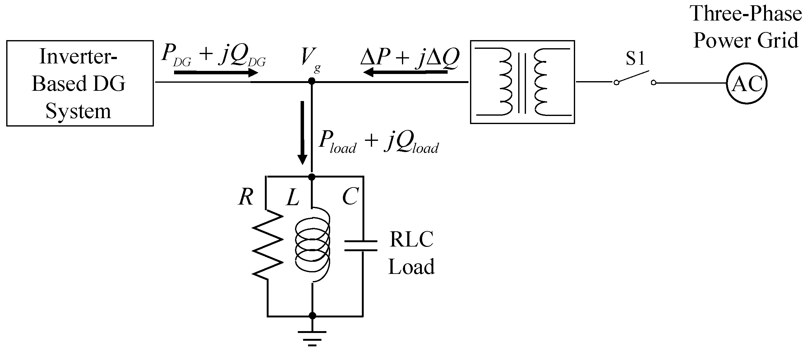
2. Inverter-Based DG System

The architecture of the inverter-based DG system for the tracking control and the proposed active islanding detection method is shown in Figure 1. The three-phase output voltages v u , v v , v w 110 Vrms of the inverter-based DG system are transformed to 220 Vrms by a transformer connected with the power grid with 60 Hz via static switch S1. Moreover, the parallel 2 kW RLC load is designed for the islanding detection according to the UL 1741 standard [8]. The resonant frequency of the RLC load is designed to be 60 ± 0.1 Hz and the quality factor Qf is set to be 2.5 as defined in UL 1741 test configuration [8,10]. Furthermore, to compute the active power and reactive power outputs of the inverter-based DG system and synchronizing with the three-phase power grid, the three-phase inverter currents i u , i v , i w and the three-phase output voltages v u , v v , v w are obtained and transferred to dq synchronous reference frame through the power calculation and phase-lock-loop (PLL) units. In addition, the following Equations (1) and (2) can express the active power PDG and reactive power QDG outputs of the DG system:
P D G = 3 2 ( v q i q + v d i d )
Q D G = 3 2 ( v q i d v d i q )
where v d and v q are the dq-axis voltages; i d and i q are the dq-axis currents. Since the PLL is adopted for synchronization, the currents are in phase with the voltages and resulted in v d = 0 .
Then, the Equations (1) and (2) can be modified in the following:
P D G = 3 2 v q i q
Q D G = 3 2 v q i d
According to (3) and (4), the active power and reactive power are proportional to i q and i d control currents respectively. By using the active and reactive power errors as inputs, the control currents i q and i d can be obtained by the PI or PFNN controllers as shown in Figure 1. Moreover, the injected perturbation signal i d i s is added to the control current i d for the islanding detection to generate the d-axis current command i d * and the control current i q is equivalent to the q-axis current command i q * . Final, the three-phase current commands i u * , i v * , i w * are computed through d q / a b c coordinate transformation and sent to the analog current control and drive circuits for generating the pulse width modulation (PWM) switching signals T a , T b , T c of the insulated gate bipolar transistors (IGBTs).

3. Active Islanding Detection Method

3.1. Non-Detection Zone

In this study, the NDZ for the islanding detection method is derived from the test circuit based on the UL 1741 testing requirement as illustrated in Figure 2 [8,33,34]. The power flows throughout the test circuit are described in the following expressions:
P D G = P l o a d Δ P
Q D G = Q l o a d Δ Q
where P D G and Q D G are the active power and reactive power outputs of the inverter-based DG system; P l o a d and Q l o a d are the active power and reactive power of the RLC load; Δ P and Δ Q are the active power and reactive power of the power grid.
According to the IEEE 1547 or UL 1741 standard [7,8], when the test circuit is connected to the power grid and the demanded power energy of the RLC load is fully supplied by the inverter-based DG system, namely ΔP = 0, ΔQ = 0, it is most difficult to detect the islanding phenomenon. Then, when the power grid breaks down, the injected perturbation signal i d i s t shown in Figure 1 will result in Q D G 0 as follows:
Q D G = V g 2 ( 1 ω g L ω g C ) = P l o a d R ( 1 ω g L ω g C )
where ω g is the angular frequency of the power grid; V g is the voltage of the RLC load. Then, the quality factor Q f = R C L is substituted into (7), and (8) can be computed in the following:
Q D G P l o a d = Q f ( 1 ω g L C ω g L C )
Moreover, since the resonant angular frequency ω o equals to be 1 / L C , Equation (8) is rewritten as:
Q D G P l o a d = Q f ( ω o ω g ω g ω o ) = Q f ( f o f g f g f o )
where f g and f o are the frequency of ω g and ω o respectively. According to IEEE 1547 standard [7], the NDZ is acquired in the following:
Q f ( f min f g f g f min ) Q D G P l o a d Q f ( f max f g f g f max )
where f max and f min are the maximum and minimum frequency thresholds respectively; Q f ( f min f g f g f min ) and Q f ( f max f g f g f max ) represent the lower limit and upper limit of the NDZ respectively.

3.2. Novel Active Islanding Detection Method Using PI Controller

In this study, an injected perturbation signal i d i s t for islanding detection is proposed. In other words, the main objective of the proposed active islanding detection method is to accelerate the frequency f at RLC load terminal to drift beyond the NDZ by injecting the perturbation signal i d i s t into the d-axis current i d when the power grid breaks down. The control block of the proposed active islanding detection method is illustrated in Figure 3. The d-axis current command i d * comprises the injected perturbation signal i d i s t and the d-axis current i d . When the power grid breaks down, the magnitude of the injected perturbation signal i d i s t becomes stronger. The analyses of the injected perturbation signal i d i s t using the traditional PI controller for the islanding detection are described in detail in the following:
i d = k P ( Q D G * Q D G ( t ) ) + k I ( Q D G * Q D G ( t ) ) d t
i d i s t = k t ( f f g )
where k P and k I are the parameters of the PI controller; k t is the gain of the injected perturbation signal; f is the frequency at the terminal of the RLC load, and f g is the frequency of the power grid.
According to (11) and (12), the current command i d * can be described as follows:
i d * ( t ) = k P ( Q D G * Q D G ( t ) ) + k I ( Q D G * Q D G ( t ) ) d t + k t ( f f g )
Since the reactive power command Q D G * is set to be zero, Equation (14) can be computed by using the Laplace transform as follows:
I d * ( s ) = k P Q D G ( s ) k I Q D G ( s ) s + k t ( f f g ) s
Hence, Q D G ( s ) can be obtained as follows:
Q D G ( s ) = I d * ( s ) k P + k I I d * ( s ) k P 2 1 s + k I k P + k t ( f f g ) k P 1 s + k I k P
Then, using the inverse Laplace transform and (16) can be calculated as follows:
Q D G ( t ) = i d * ( t ) k P + k I i d * ( t ) k P 2 e k I k P t + k t ( f f g ) k P e k I k P t
When the power grid breaks down without injecting the perturbation signal i d i s t , the RLC load is operated at resonant frequency 60 Hz and regarded as a resistive load. Therefore, the reactive power output Q D G of the inverter-based DG system is close to be zero. Then, by substituting Q D G 0 into (10), equation (17) can be acquired in the following:
Q f ( f min f g f g f min ) 0 Q f ( f max f g f g f max )
In accordance with Equation (17), since the term Q D G P l o a d shown in (9) is within the NDZ, the islanding phenomenon will be occurred in the system. Meanwhile, the frequency f at the terminal of the RLC load equals to the resonant frequency f o , and f min f o f max . Hence, in this scenario, the islanding phenomenon can’t be detected by a passive islanding detection method such as the under/over frequency method. However, when the power grid breaks down with the injected perturbation signal i d i s t , the instantaneous change f f g will cause the reactive power output Q D G to drift from zero. Hence, replacing (10) with (16), the injected perturbation signal i d i s t with the PI controller can accelerate the frequency to deviate from NDZ for both upper and lower limits which are described respectively in the following:
i d * ( t ) k P P l o a d + k I i d * ( t ) k P 2 P l o a d e k I k P t + k t ( f f g ) k P P l o a d e k I k P t Q f ( f min f g f g f min )
i d * ( t ) k P P l o a d + k I i d * ( t ) k P 2 P l o a d e k I k P t + k t ( f f g ) k P P l o a d e k I k P t Q f ( f max f g f g f max )
Since the terms i d * , k P , k I , k t , f g and P l o a d are positive values, the lower limit of NDZ represented in (18) is obtained with the following expression:
f k P P l o a d k t e k I k P t [ Q f ( f min f g f g f min ) + i d * ( t ) k P P l o a d k I i d * ( t ) k P 2 P l o a d e k I k P t ] f g
Moreover, equation (20) can be simplified as f A f g , in which A is a time-varying value. When the power grid breaks down, if the value f A is smaller than f g , the system will deviate from the lower limit of NDZ. Hence, the islanding phenomenon can be detected and the inverter-based DG system stops dispatching the generated power energy. On the other hand, the upper limit of NDZ represented in (19) can be obtained as follows:
f k P P l o a d k t e k I k P t [ Q f ( f max f g f g f max ) + i d * ( t ) k P P l o a d k I i d * ( t ) k P 2 P l o a d e k I k P t ] f g
Equation (21) can be also simplified as f B f g , in which B is a time-varying value. If the value f B is larger than f g , the system will deviate from the upper limit of NDZ. Therefore, the islanding phenomenon can be also detected and the inverter-based DG system stops dispatching the generated power energy to the RLC load.
The proposed injection perturbation method mainly injects the frequency difference signal f f g into the d-axis current. When the power grid is connected, the error of frequency of the injected perturbation signal i d i s t is closed to be zero. Hence, the proposed active islanding detection method will have no impact on the power quality and the inverter-based DG system.

4. Probabilistic Fuzzy Neural Network

For the purpose of improving the transient and steady-state responses of the active and reactive power outputs of the inverter-based DG system and decreasing the detection time of the islanding phenomenon, the PFNN controllers proposed in [31,32] are adopted to take the place of the traditional PI controller in this study. The detailed introduction of the proposed PFNN is represented in the following:

4.1. Network Structure

The network structure of the adopted PFNN is represented in Figure 4 [31,32,34]. The PFNN control owns five layers including the input layer, the membership layer, the probabilistic layer, the rule layer, and the output layer with two inputs and one output. Moreover, the basic function of each layer and the signal propagation are presented in the following:

Input Layer (Layer 1):

The relationships of the input and output of this layer are represented as follows:
x i ( N ) = e i ( N ) , i = 1 , 2
where N represents the Nth iteration. In this study, the inputs of the PFNN are e 1 ( N ) = e   and e 2 ( N ) = e ˙ , and the input items are e = P D G * P D G for the active power control and e = Q D G * Q D G for the reactive power control.

Membership Layer (Layer 2):

A triangular function f m ( x i ) is adopted as the receptive field function to reduce the computational requirements in this layer. The triangular function f m ( x i ) is described as:
μ j ( x i ) = f m ( x i ) = { 0 i f x i m j + σ j , x i m j σ j x i m j + σ j σ j i f m j σ j < x i m j x i + m j + σ j σ j i f m j < x i m j + σ j i = 1 , 2 . j = 1 , 2 , , 6
where σ j is the center’s width of the triangle; m j is the center of the triangle and μ j ( x i ) is the output of the jth node of the ith input variable.

Probabilistic Layer (Layer 3):

In this layer, another triangular function f p ( μ j ) is chosen as the receptive field function and given in the following:
P k ( μ j ) = f p ( μ j ) = { 0 i f μ j m k + σ k , μ j m k σ k μ j m k + σ k σ k i f m k σ k < μ j m k μ j + m k + σ k σ k i f m k < μ j m k + σ k k = 1 , 2 , . , 18
where σ k is the center’s width of the triangle; m k is the center of the triangle and P k ( μ j ) is the output of the kth node of the jth input variable.

Rule Layer (Layer 4):

In the Mamdani inference, the node itself implements the product operation to acquire the inference set in accordance with the rules as shown in (25). The probabilistic information is performed using the Bayes’ theorem [35] in consideration of the group of fuzzy grade being independent variables as shown in (26). Thus, the relationships of the input and output of this layer are described as:
μ l I = j w j l μ j
P l I = k w k l P k
μ l O = μ l I P l I l = 1 , 2 , , 9
where μ l I and P l I are the input of the rule layer; w j l and w k l are the connected weights which are all set to be 1; μ l O is the output of the rule layer.

Output Layer (Layer 5):

In output layer, the input and the output are gained in the following:
Δ i = y ( N ) = l = 1 9 w l μ l O
where Δ i = y ( N ) is the output of the PFNN; w l is the connected weight between the rule layer and the output layer. Moreover, y ( N ) = i q * for the active power control, and y ( N ) = i d * for the reactive power control and islanding detection.

4.2. Online Learning Using Backpropagation Algorithm

In accordance with the chain rule, the online learning algorithm of the adopted PFNN is performed for the derivative of an energy function with respect to a parameter of the network. Thus, in order to derive the online learning algorithm of the adopted PFNN, the energy function E is defined as:
E = 1 2 ( P D G * P D G ) 2 = 1 2 e 2
Then the online learning algorithm is introduced in detail in the following:

Output Layer:

The propagation of the error term is calculated as:
δ o = E y ( N ) = E P D G P D G y ( N )
Then, the updated amount of the connected weight is given in the following:
Δ w l = η 1 E w l = η 1 E y ( N ) y ( N ) w l = η 1 δ o μ l O
where η 1 is the learning rate. Moreover, the connected weight w l is updated as follows:
w l ( N + 1 ) = w l ( N ) + Δ w l

Rule Layer:

In this layer, the propagation of the error term is calculated as:
δ l = E μ l O = E y ( N ) y ( N ) μ l O = δ o w l

Membership Layer:

In membership layer, the error terms to be propagated are calculated as:
δ j = E μ j = E y ( N ) y ( N ) μ l O μ l O μ l I μ l I μ j = l δ l P l I
According to the chain rule, the updated amounts of center and center’s width of the triangle are computed respectively as follows:
Δ m j = η 2 E m j = η 2 E y ( N ) y ( N ) μ l O μ l O μ l I μ l I μ j μ j m j    = { η 2 δ j 1 σ j i f m j σ j < x i m j η 2 δ j 1 σ j    i f m j < x i m j + σ j
Δ σ j = η 3 E σ j = η 3 E y ( N ) y ( N ) μ l O μ l O μ l I μ l I μ j μ j σ j    = { η 3 δ j m j x i ( σ j ) 2 i f m j σ j < x i m j η 3 δ j x i m j ( σ j ) 2 i f m j < x i m j + σ j
where η 2 and η 3 are the learning rates. The center of the triangle m j and center’s width of the triangle σ j are updated in accordance with the following equations:
m j ( N + 1 ) = m j ( N ) + Δ m j
σ j ( N + 1 ) = σ j ( N ) + Δ σ j
Owing to the uncertainties of the plant dynamic such as external disturbances and parameter variations, the exact calculation of the Jacobian of the controlled plant, P D G / y ( N ) and Q D G / y ( N ) can’t be obtained. To solve the problem and increase the online learning speed of the connected weights, the delta adaptation law is adopted in the following:
δ o e ( N ) + e ˙ ( N )

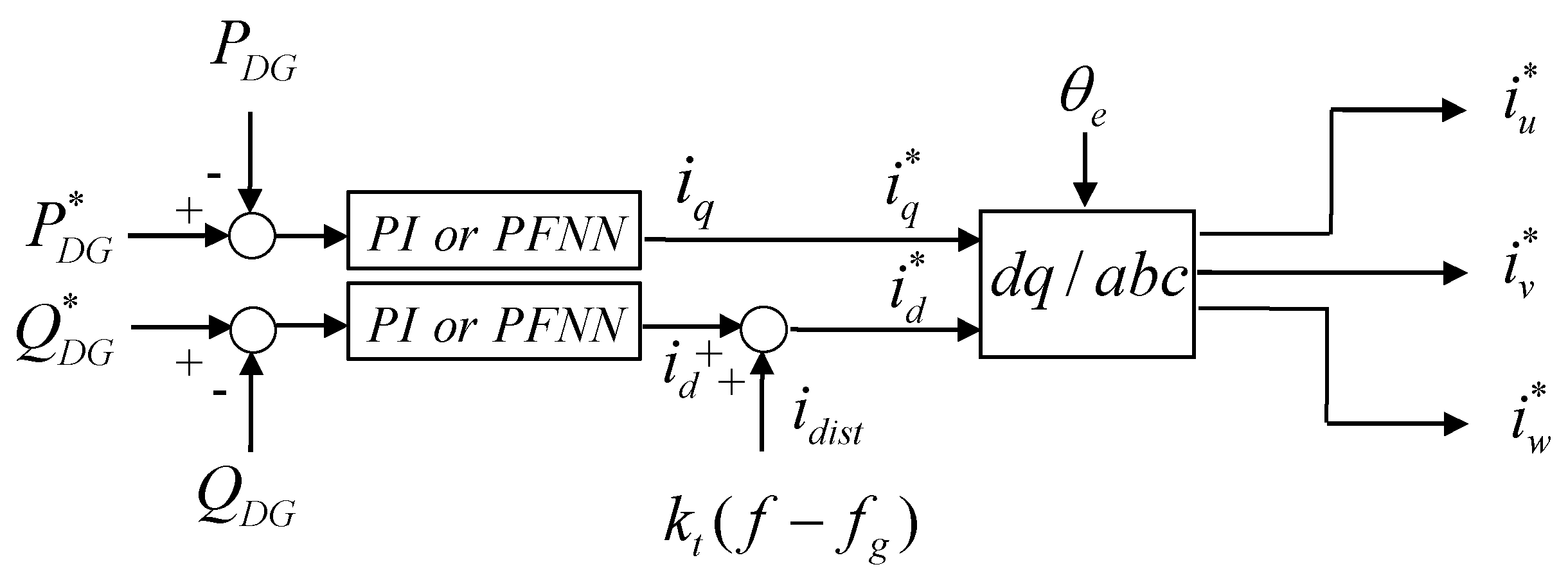
5. Novel Active Islanding Detection Using PFNN Controller

The objective of the proposed active islanding detection method using the PFNN controller is to reduce the detection time of islanding phenomenon. Moreover, the output of the PFNN controller can be described in (28). Hence, the analyses of the d-axis current i d and d-axis current command i d * using the PFNN controller for the islanding detection are described in detail as follows:
i d = [ l = 1 9 w l μ l O ] ( Q D G * Q D G ( t ) )
i d * ( t ) = [ l = 1 9 w l μ l O ] ( Q D G * Q D G ( t ) ) + k t ( f f g )
Since the reactive power command Q D G * is set to be zero, Q D G ( t ) can be obtained as follows:
Q D G ( t ) = i d * ( t ) + k t ( f f g ) l = 1 9 w l μ l O
Then, substitute (42) into (10), the injected perturbation signal i d i s t with the PFNN controller can accelerate the frequency to deviate from NDZ for both upper and lower limits which are represented respectively in the following:
i d * ( t ) + k t ( f f g ) [ l = 1 9 w l μ l O ] P l o a d Q f ( f min f g f g f min )
i d * ( t ) + k t ( f f g ) [ l = 1 9 w l μ l O ] P l o a d Q f ( f max f g f g f max )
Furthermore, (43) can be further represented as follows:
f Q f ( f min f g f g f min ) [ l = 1 9 w l μ l O ] P l o a d + i d * ( t ) k t f g
Then, (45) can be simplified as f C f g , in which C is a time-varying value. When the power grid breaks down, if the value f C is smaller than f g , the system will deviate from the lower limit of NDZ. Hence, the islanding phenomenon can be detected and the inverter-based DG system stops dispatching the generated power energy to the RLC load. On the other hand, (44) can be also represented as follows:
f Q f ( f max f g f g f max ) [ l = 1 9 w l μ l O ] P l o a d + i d * ( t ) k t f g
In addition, (46) can be also simplified as f D f g , in which D is also a time-varying value. If the value f D is larger than f g , the system will also deviate from the upper limit of NDZ. Therefore, the islanding phenomenon can be detected and the inverter-based DG system stops dispatching the generated power energy. Since the term l = 1 9 w l μ l O in (43) and (44) is the output of the adopted PFNN controller, the capabilities of the PFNN such as fast convergence and online learning will make (43) and (44) to deviate from the upper or lower limit of the NDZ rapidly when the power grid breaks down.

6. Design and Experimental Results

6.1. Design

The block diagram of 2 kW voltage source inverter (VSI) of DG system and the photos of the laboratory setups for the tracking control and islanding detection are shown in Figure 5. The block diagram of the personal computer (PC)-based control computer is provided in Figure 5a. The switch S1 represents the circuit breaker and a DC power supply with 2 kW 200V 10 A is adopted to emulate the DC source of a DG. The parallel 2 kW RLC load is regarded as a local load and the resonant frequency is designed to be 60 ± 0.1 Hz in accordance with the UL 1741 standard [8] for the islanding detection. The values of the parallel 2 kW RLC load are designed to be R = 6.05 Ω , L = 6.42 mH and C = 1096 μF respectively. The output inductors L of the inverter are 10 mH and the DC-link capacitor is 3360 μF. Moreover, when the frequency of the power grid is 60 Hz, the RLC load is considered as a resistive load. If the power grid breaks down and the demanded power energy of the RLC load is fully supplied by the inverter-based DG system, without the efficacious islanding detection method, the frequency and output voltage of the inverter-based DG system will be retained as same as the power grid resulting in the islanding phenomenon. Thus, the designed test system can be implemented to verify if the islanding detection method is efficacious. Furthermore, the control algorithms, including the PFNN control, the PLL and the proposed active islanding detection method, are carried out by the Matlab & Simulink Real-Time Control package with 0.5 ms sampling time. Then, in order to implement the active and reactive power outputs of the inverter-based DG system and to detect the islanding phenomenon, the three-phase output voltages v u , v v , v w and the three-phase inverter currents i u , i v , i w are obtained by the sensor circuits and sent to the PC through the PCI-1716 analog/digital (A/D) control card. The generated current commands i u * , i v * , i w * are sent to the analog current control and drive circuits via PCI-1723 digital/analog (D/A) converter. Thus, the PWM switching signals T a ,   T b   , T c of IGBTs for the tracking control and the islanding detection can be gained. Additionally, the photos of the laboratory setups are provided in Figure 5b.

6.2. Experimental Results of Tracking Control

First, the experimental results of the inverter-based DG system using the PI controllers for the tracking control of the active power and reactive power outputs are provided to demonstrate the tracking performance of the system with the injected perturbation signal idist. In this study, the gains of the PI controllers are obtained by trial and error in order to achieve good transient and steady-state control performance. The resulted gains are kP = 2 and kI = 0.5, respectively. The experimental result of the inverter-based DG system using the PI controllers for active power command from 0 kW to 1 kW, 1 kW to 2 kW and reactive power command set to be 0 Var is provided in Figure 6. The responses of the active power output and active power command and the reactive power output and reactive power command are shown in Figure 6a,b, respectively. From the experimental result, the steady- state responses of the active power output at 1 kW and 2 kW can achieve the tracking effectiveness as shown in Figure 6a. However, for the transient responses, since the traditional PI controllers are not robust in coping with the system uncertainties such as parameter variations and external disturbances, the transient responses of the active power output from 0 kW to 1 kW and 1 kW to 2 kW are poor. Moreover, the transient response of the reactive power output will also be seriously affected as shown in Figure 6b.
Hence, for the purpose of achieving superior transient and steady-state responses of the active and reactive power outputs of the inverter-based DG system, two online learning PFNN controllers are adopted to take the place of the traditional PI controller in the inverter-based DG system. The experimental result of the inverter-based DG system using the PFNN controllers is provided in Figure 7. The responses of the active power output and active power command and the reactive power output and reactive power command are shown in Figure 7a,b, respectively.
From the experimental results, the PFNN controller can eliminate the transient errors of the active power output and reactive power output more rapidly as shown in Figure 7a,b. Comparing to the PI controller, since the connected weights, mean and standard deviation of the membership functions are trained online, the adopted PFNN controller possesses fast convergence ability with adaptivity. Thus, the superior tracking control of the active power and reactive power outputs can be obtained for the inverter-based DG system using PFNN controllers. In addition, the injected perturbation signal idist has no impact on the active and reactive power outputs of the inverter-based DG system. Therefore, the power quality can be also guaranteed.

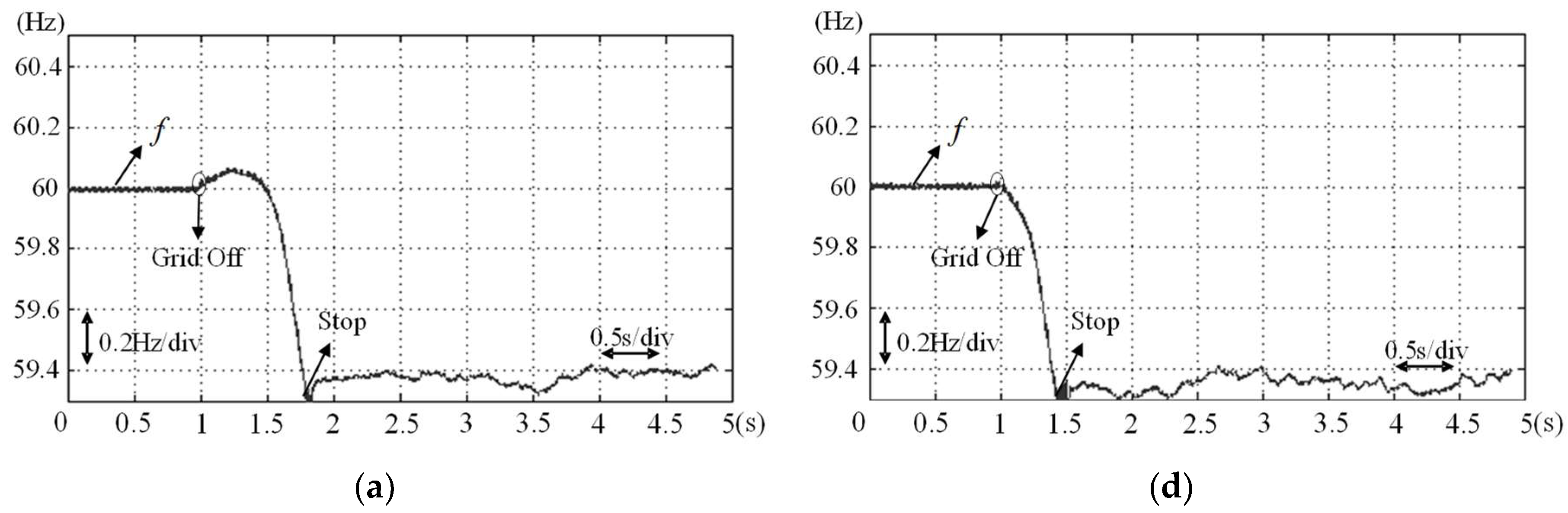
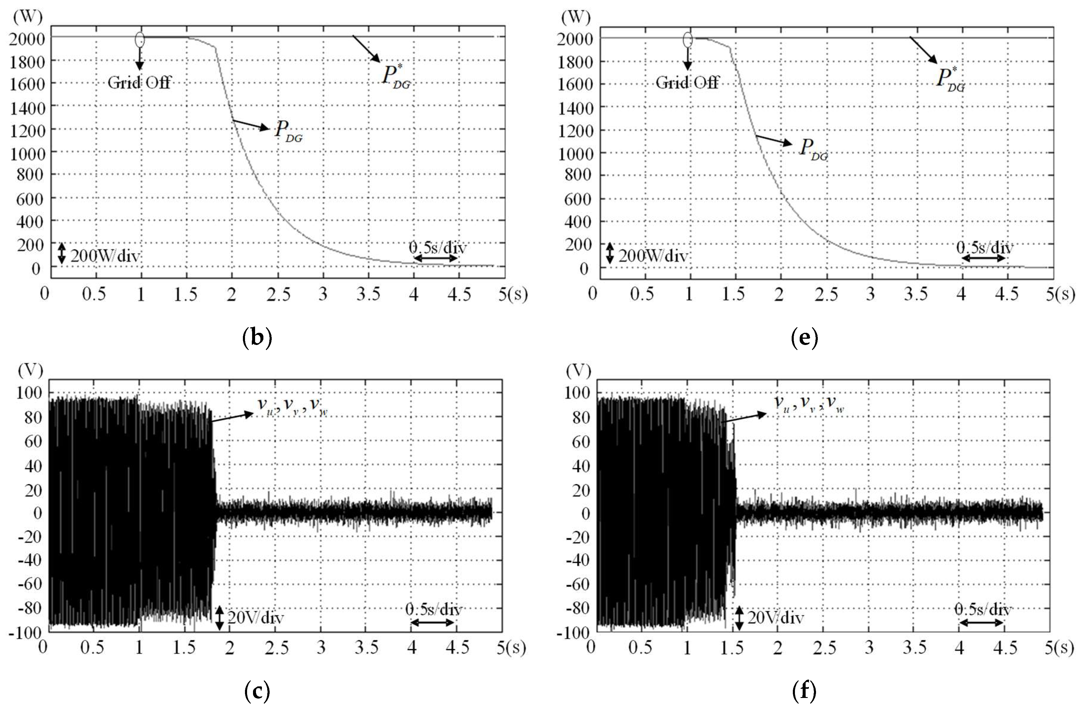
6.3. Experimental Results of Islanding Detection

In order to verify the effectiveness of the proposed active islanding detection method, three test scenarios are designed in the following: (1) in Case1, the power grid is operated at 60 Hz; (2) in Case 2 the power grid is operated at 59.9 Hz, and (3) in Case 3, the power grid is operated at 60.1 Hz. When the S1 shown in Figure 1 is opened, the power grid breaks down. Moreover, the active power command P D G * is set to be 2 kW in the test scenarios to model the worst case [7,8]. First, the experimental results of the proposed active islanding detection method using PI and the adopted PFNN controllers at case 1 are provided in Figure 8 to demonstrate the islanding detection. The responses of the frequency at the terminal of the RLC load, the active power output and the voltage at the terminal of the RLC load using PI controllers are shown in Figure 8a–c, respectively. The responses of the frequency at the terminal of the RLC load, the active power output and the voltage at the terminal of the RLC load using the adopted PFNN controllers are shown in Figure 8d–f, respectively. The power grid breaks down at 1 s. When the proposed active islanding detection method uses the traditional PI controllers, the inverter-based DG system continues to dispatch the generated active power to the RLC load until the time 1.8 s as shown in Figure 8a.
After 1.8 s, the injected perturbation signal idist is large enough to drift the frequency to deviate from the IEEE 1547 scope (59.3–60.5 Hz). In Figure 8b–c, the total time for the inverter-based DG system stops dispatching the generated power is about 0.8 s which meets the IEEE 1547 regulations within 2 s. On the other hand, when the proposed active islanding detection method adopts the proposed PFNN controllers, the islanding phenomenon can be detected immediately in 0.45 s as shown in Figure 8d. Compared to the experimental results of the proposed active islanding detection method using the traditional PI controllers operated at case 1 shown in Figure 8a–c, due to the advantages of the adopted PFNN controllers such as online learning and fast convergence, the responses of the proposed active islanding detection method using the adopted PFNN controllers can rapidly detect the islanding phenomenon shown in Figure 8d–f.
In addition, the experimental results of the proposed active islanding detection method using PI and the adopted PFNN controllers operated at case 2 are shown in Figure 9.
The responses of the frequency at the terminal of the RLC load, the active power output and the voltage at the terminal of the RLC load using PI controllers are shown in Figure 9a–c, respectively. The responses of the frequency at the terminal of the RLC load, the active power output and the voltage at the terminal of the RLC load using the adopted PFNN controllers are shown in Figure 9d–f, respectively. According to the experimental results as shown in Figure 9a,d, the detection time using the PI and the adopted PFNN controllers are 0.35 s and 0.3 s, respectively. The performance of the proposed active islanding detection method using the adopted PFNN controllers is also superior than PI controllers. Additionally, the experimental results using PI and the adopted PFNN controllers in Case 3 are provided in Figure 10. The time to detect the islanding phenomenon using PI and the adopted PFNN controllers at case 3 are 0.9 s and 0.7 s respectively. Final, the detection time of proposed active islanding detection method using different controllers in cases 1–3 are provided in Table 1. According to the experimental results shown in Figure 8, Figure 9 and Figure 10 and Table 1, the detection time of the proposed active islanding detection method using the adopted PFNN controllers are all faster than the proposed active islanding detection method using the traditional PI controller. Therefore, the proposed active islanding detection method using PFNN controllers has superior performance for the islanding detection due to the powerful robust ability of the PFNN controllers.

7. Conclusions

This study successfully presented the development and implementation of the inverter-based DG system for the tracking control and the islanding detection. Moreover, a new active islanding detection method is proposed. Furthermore, the online trained PFNN controller is adopted to take the place of the traditional PI controller for the tracking control and the islanding detection. The proposed active islanding detection method, the network structure and online learning based on BP algorithm of the PFNN controller have been introduced in detail. In addition, the analysis for the integration of the proposed active islanding detection method and the PFNN controller has been derived. Then, the experimental results verify that the proposed active islanding detection method can accelerate the frequency to drift beyond the NDZ rapidly. Therefore, the major contributions of this study are: (1) successful development of a method for islanding detection; (2) successful design of two PFNN controllers for the active power and reactive power control of the inverter-based DG system; (3) successful integration of the proposed active islanding detection method and the PFNN controller for islanding detection.

Author Contributions

K.-H.T. designed and developed the main parts of the research work, including the analyses of the experimental results. K.-H.T. and C.-W.L. were responsible for preparing the paper.

Funding

This research received no external funding.

Conflicts of Interest

The authors declare no conflict of interest.

References

  1. Chen, X.; Li, Y. An islanding detection method for inverter-based distributed generators based on the reactive power disturbance. IEEE Trans. Power Electron. 2016, 31, 3559–3574. [Google Scholar] [CrossRef]
  2. Park, S.; Kwon, M.; Choi, S. Reactive power P&O anti-islanding method for a grid-connected inverter with critical load. IEEE Trans. Power Electron. 2019, 34, 204–212. [Google Scholar]
  3. Ghalavand, F.; Alizade, B.A.M.; Gaber, H.; Karimipour, H. Microgrid islanding detection based on mathematical morphology. Energies 2018, 11, 2696. [Google Scholar] [CrossRef]
  4. Sun, Q.; Guerrero, J.M.; Jing, T.; Vasquez, J.C.; Yang, R. An islanding detection method by using frequency positive feedback based on FLL for single-phase microgrid. IEEE Trans. Smart Grid 2017, 8, 1821–1830. [Google Scholar] [CrossRef]
  5. Al Hosani, M.; Qu, Z.; Zeineldin, H.H. Development of dynamic estimators for islanding detection of inverter-based DG. IEEE Trans. Power Deliv. 2015, 30, 428–436. [Google Scholar] [CrossRef]
  6. Makwana, Y.M.; Bhalja, B.R. Experimental performance of an islanding detection scheme based on modal components. IEEE Trans. Smart Grid 2019, 10, 1025–1035. [Google Scholar] [CrossRef]
  7. IEEE Standard for Interconnecting Distributed Resources with Electric Power Systems; IEEE Std. 1547-2003; IEEE Standard Association: Piscataway, NJ, USA, 2003.
  8. Inverters, Converters, and Controllers for Use in Independent Power Systems; UL Std. 1741; Underwriters Laboratories Inc.: Northbrook, IL, USA, 2002.
  9. Kim, J.H.; Kim, J.G.; Ji, Y.H.; Jung, Y.C.; Won, C.Y. An islanding detection method for a grid-connected system based on the goertzel algorithm. IEEE Trans. Power Electron. 2011, 26, 1049–1055. [Google Scholar] [CrossRef]
  10. Khodaparastan, M.; Vahedi, H.; Khazaeli, F.; Oraee, H. A novel hybrid islanding detection method for inverter-based DGs using SFS and ROCOF. IEEE Trans. Power Deliv. 2017, 32, 2162–2170. [Google Scholar] [CrossRef]
  11. Faqhruldin, O.N.; El-Saadany, E.F.; Zeineldin, H.H. A universal islanding detection technique for distributed generation using pattern recognition. IEEE Trans. Smart Grid 2014, 5, 1985–1992. [Google Scholar] [CrossRef]
  12. Liu, N.; Aljankawey, A.; Diduch, C.; Chang, L.; Su, J. Passive islanding detection approach based on tracking the frequency-dependent impedance change. IEEE Trans. Power Deliv. 2015, 30, 2570–2580. [Google Scholar] [CrossRef]
  13. Najy, W.K.A.; Zeineldin, H.H.; Kasem Alaboudy, A.H.; Woon, W.L. A bayesian passive islanding detection method for inverter-based distributed generation using ESPRIT. IEEE Trans. Power Deliv. 2011, 26, 2687–2696. [Google Scholar] [CrossRef]
  14. Ropp, M.E.; Begovic, M.; Rohatgi, A.; Kern, G.A.; Bonn, R.H.; Gonzalez, S. Determining the relative effectiveness of islanding detection methods using phase criteria and nondetection zones. IEEE Trans. Energy Convers. 2000, 15, 290–296. [Google Scholar] [CrossRef]
  15. Vahedi, H.; Gharehpetian, G.B.; Karrari, M. Application of duffing oscillators for passive islanding detection of inverter-based distributed generation units. IEEE Trans. Power Deliv. 2012, 27, 1973–1983. [Google Scholar] [CrossRef]
  16. Reigosa, D.; Briz, F.; Charro, C.B.; Garcia, P.; Guerrero, J.M. Active islanding detection using high-frequency signal injection. IEEE Trans. Ind. Appl. 2012, 48, 1588–1597. [Google Scholar] [CrossRef]
  17. Zeineldin, H.H.; Conti, S. Sandia frequency shift parameter selection for multi inverter systems to eliminate non-detection zone. IET Renew. Power Gener. 2011, 5, 175–183. [Google Scholar] [CrossRef]
  18. Wang, X.; Freitas, W. Impact of positive-feedback anti-islanding methods on small-signal stability of inverter-based distributed generation. IEEE Trans. Energy Convers. 2008, 23, 923–931. [Google Scholar] [CrossRef]
  19. Liu, F.; Kang, Y.; Zhang, Y.; Duan, S.; Lin, X. Improved SMS islanding detection method for grid-connected converters. IET Renew. Power Gener. 2010, 4, 36–42. [Google Scholar] [CrossRef]
  20. Timbus, A.; Oudalov, A.; Ho, C.N.M. Islanding detection in smart grids. In Proceeding of the IEEE Energy Conversion Congress and Exposition, Atlanta, GA, USA, 12–16 September 2010; pp. 3631–3637. [Google Scholar]
  21. Xu, W.; Zhang, G.; Li, C.; Wang, W.; Wang, G.; Kliber, J. A power line signaling based technique for anti-islanding protection of distributed generators—Part I: Scheme and analysis. IEEE Trans. Power Deliv. 2007, 22, 1758–1766. [Google Scholar] [CrossRef]
  22. Lin, F.J.; Lu, K.C.; Ke, T.H.; Yang, B.H.; Chang, Y.R. Reactive power control of three-phase grid-connected PV system during grid faults using takagi–sugeno–kang probabilistic fuzzy neural network control. IEEE Trans. Ind. Electron. 2015, 62, 5516–5528. [Google Scholar] [CrossRef]
  23. Tan, K.H. Squirrel-cage induction generator system using wavelet petri fuzzy neural network control for wind power applications. IEEE Trans. Power Electron. 2016, 31, 5242–5245. [Google Scholar] [CrossRef]
  24. Tan, K.H.; Lin, F.J.; Tsai, C.Y.; Chang, Y.R. A distribution static compensator using a CFNN-AMF controller for power quality improvement and DC-link voltage regulation. Energies 2018, 11, 1996. [Google Scholar] [CrossRef]
  25. Tan, K.H.; Lin, F.J.; Chen, J.H. DC-link voltage regulation using RPFNN-AMF for three-phase active power filter. IEEE Access 2018, 6, 37454–37463. [Google Scholar] [CrossRef]
  26. Rubaai, A.; Young, P. Hardware/software implementation of fuzzy-neural-network self-learning control methods for brushless DC motor drives. IEEE Trans. Ind. Appl. 2016, 52, 414–424. [Google Scholar] [CrossRef]
  27. Beritelli, F.; Capizzi, G.; Sciuto, G.L.; Napoli, C.; Scaglione, F. Rainfall estimation based on the intensity of the received signal in a LTE/4G mobile terminal by using a probabilistic neural network. IEEE Access 2018, 6, 30865–30873. [Google Scholar] [CrossRef]
  28. Specht, D.F. Probabilistic neural network. Neural Netw. 1990, 3, 109–118. [Google Scholar] [CrossRef]
  29. Tripathy, M.; Maheshwari, R.P.; Verma, H.K. Probabilistic neural-network-based protection of power transformer. IET Electr. Power Appl. 2007, 1, 793–798. [Google Scholar] [CrossRef]
  30. Perera, N.; Rajapakse, A.D. Recognition of fault transients using a probabilistic neural-network classifier. IEEE Trans. Power Deliv. 2011, 26, 410–419. [Google Scholar] [CrossRef]
  31. Lin, F.J.; Tan, K.H. Squirrel-cage induction generator system using probabilistic fuzzy neural network for wind power applications. In Proceeding of the IEEE International Conference on Fuzzy Systems, Istanbul, Turkey, 2–5 August 2015; pp. 1–8. [Google Scholar]
  32. Lin, F.J.; Huang, Y.S.; Tan, K.H.; Lu, Z.H.; Chang, Y.R. Intelligent-controlled doubly fed induction generator system using PFNN. Neural Comput. Appl. 2013, 22, 1695–1712. [Google Scholar] [CrossRef]
  33. Lin, F.J.; Huang, Y.S.; Tan, K.H.; Chiu, J.H.; Chang, Y.R. Active islanding detection method using d-axis disturbance signal injection with intelligent control. IET Gener. Transm. Distrib. 2013, 7, 537–550. [Google Scholar] [CrossRef]
  34. Tan, K.H.; Hu, C.C.; Lan, C.W.; Lin, S.S.; Chang, T.J. Active islanding detection method using intelligent controller. Int. J. Electr. Comput. Energ. Electron. Commun. Eng. 2016, 10, 1–7. [Google Scholar]
  35. Kowalski, P.A.; Kusy, M. Sensitivity analysis for probabilistic neural network structure reduction. IEEE Trans. Neural Netw. Learn. Syst. 2018, 29, 1919–1932. [Google Scholar] [CrossRef] [PubMed]
Figure 1. Circuit architecture of the inverter-based DG system.
Energies 12 00506 g001
Figure 2. Power flowers of test circuit based on UL 1741.
Energies 12 00506 g002
Figure 3. Control block of proposed active islanding detection method.
Energies 12 00506 g003
Figure 4. Network structure of PFNN.
Energies 12 00506 g004
Figure 5. DG system for tracking control and islanding detection: (a) Block diagram of the PC-based control computer; (b) Photos of the PC-based laboratory setup.
Energies 12 00506 g005aEnergies 12 00506 g005b
Figure 6. Experimental result of DG using PI controllers for active and reactive power control: (a) Response of active power; (b) Response of reactive power.
Energies 12 00506 g006aEnergies 12 00506 g006b
Figure 7. Experimental result of DG using PFNN controllers for active and reactive power control: (a) active power Response of; (b) Response of reactive power.
Energies 12 00506 g007
Figure 8. Experimental results of proposed active islanding detection method at case 1: (a) Frequency response using PI controllers; (b) Responses of active power output using PI controllers; (c) Voltage response using PI controllers; (d) Frequency response using adopted PFNN controllers; (e) Responses of active power output using adopted PFNN controllers; (f) Voltage response using adopted PFNN controllers.
Energies 12 00506 g008aEnergies 12 00506 g008b
Figure 9. Experimental results of proposed active islanding detection method at case 2: (a) Frequency response using PI controllers; (b) Responses of active power output using PI controllers; (c) Voltage response using PI controllers; (d) Frequency response using adopted PFNN controllers; (e) Responses of active power output using adopted PFNN controllers; (f) Voltage response using adopted PFNN controllers.
Energies 12 00506 g009aEnergies 12 00506 g009b
Figure 10. Experimental results of proposed active islanding detection method at case 3: (a) Frequency response using PI controllers; (b) Responses of active power output using PI controllers; (c) Voltage response using PI controllers; (d) Frequency response using adopted PFNN controllers; (e) Responses of active power output using adopted PFNN controllers; (f) Voltage response using adopted PFNN controllers.
Energies 12 00506 g010aEnergies 12 00506 g010b
Table 1. Detection time of proposed active islanding detection method using different controllers at case 1–3.
ControllerDetection Time (S)
Case 1
(60 Hz)
Case 2
(59.9 Hz)
Case 3
(60.1 Hz)
PI0.80.350.9
PFNN0.450.30.7

