A Novel Process for Production of Calophyllum Inophyllum Biodiesel with Electromagnetic Induction

 ,
,
Abstract
:1. Introduction
2. Basic Principle
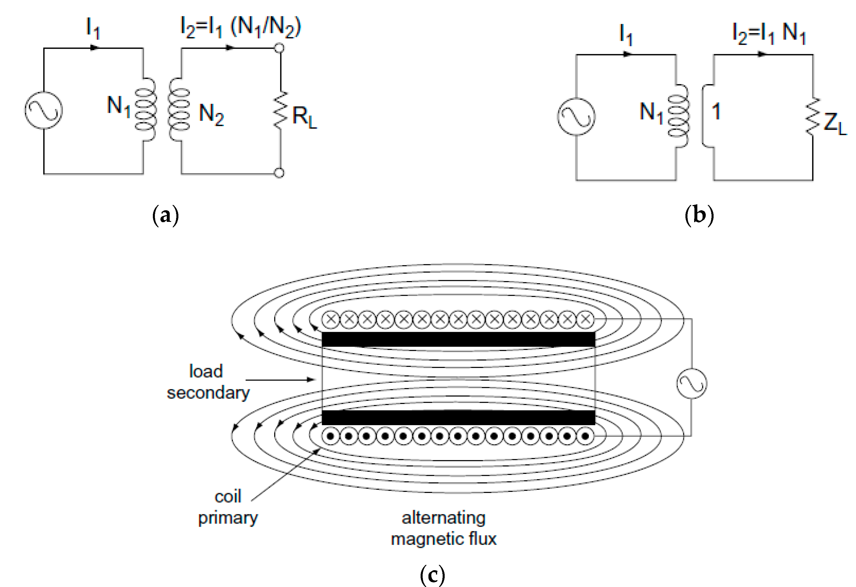
2.1. Electromagnetic Induction
- R = Resistance is determined by resistivity (ρ) and permeability (μ) of conductive objects
- i = Current is determined by the magnetic of field intensity.
- E = Induction voltage
- P = Power
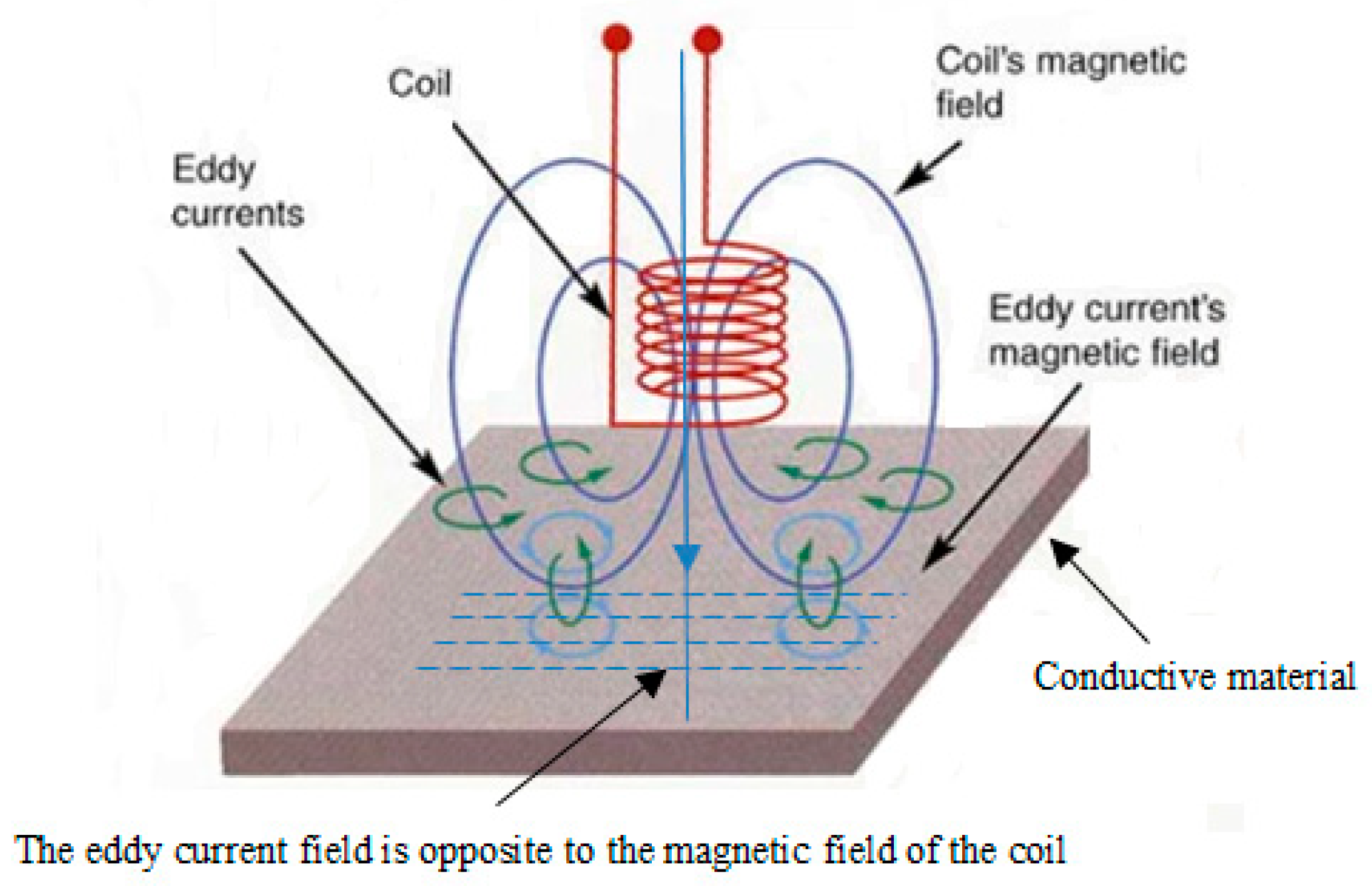
2.2. Eddy Current
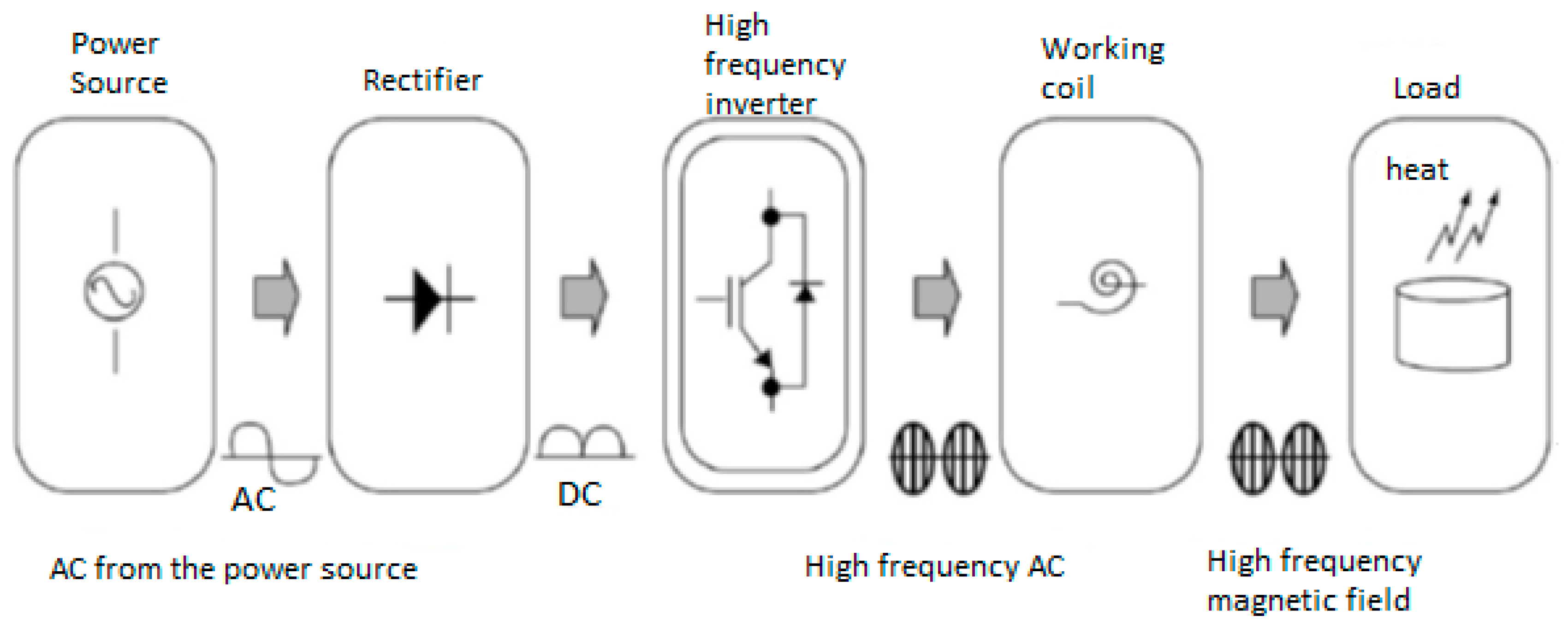
2.3. Operating Fundamental of an IH
3. Topology of IH
3.1. Power System of IH
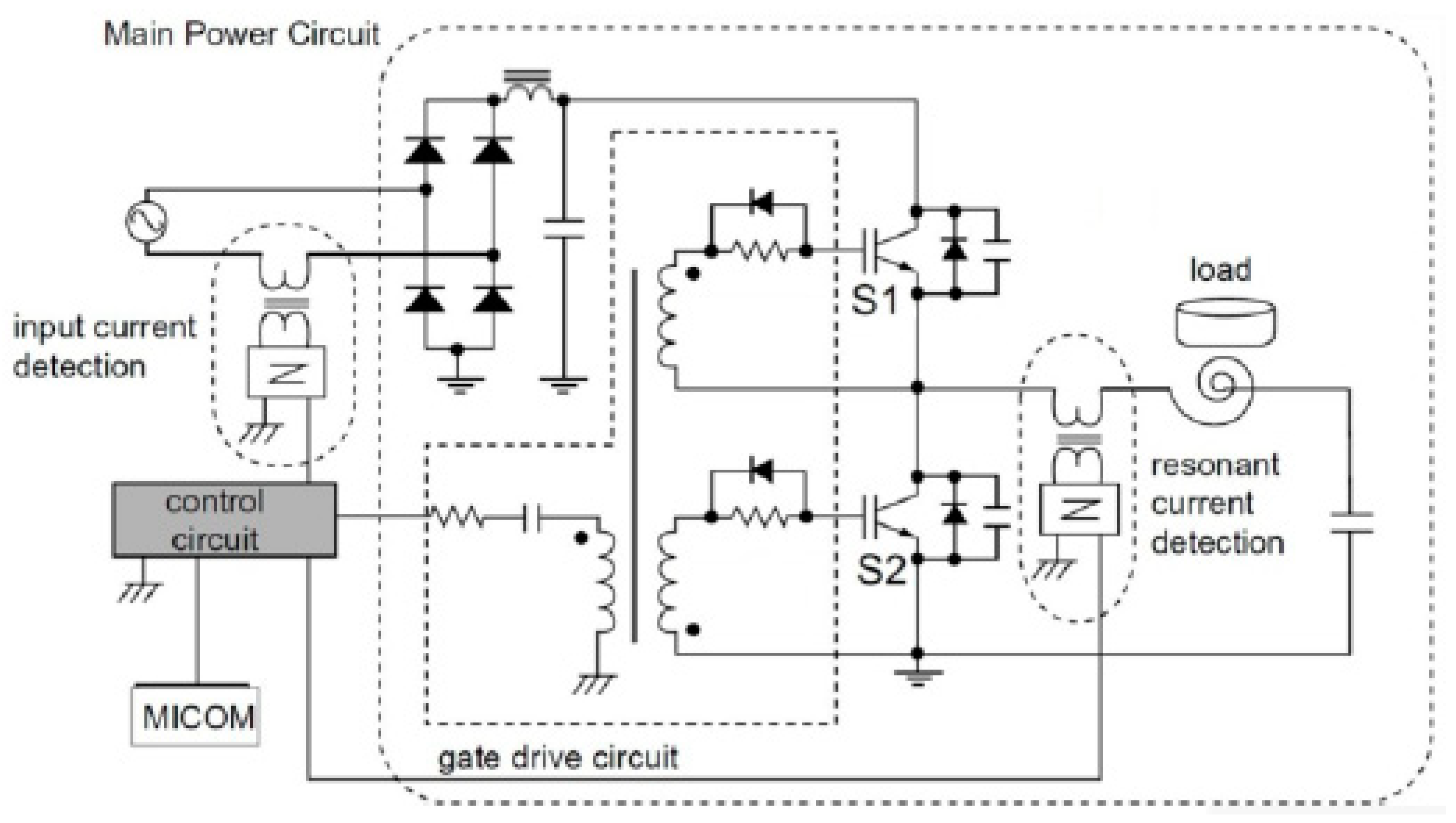
3.2. Half-Bridge Resonance Inverter
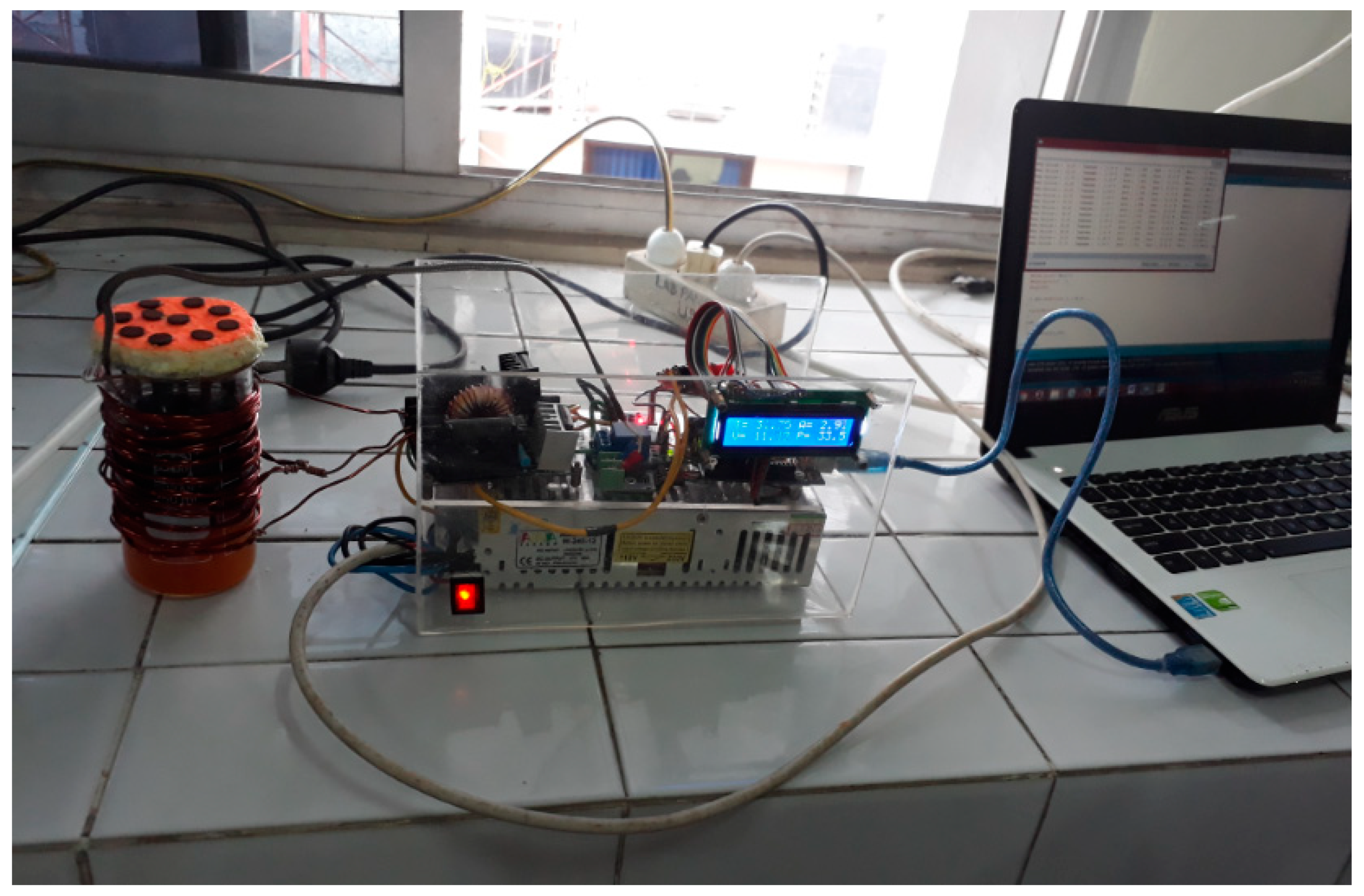
4. Experimental Set-up
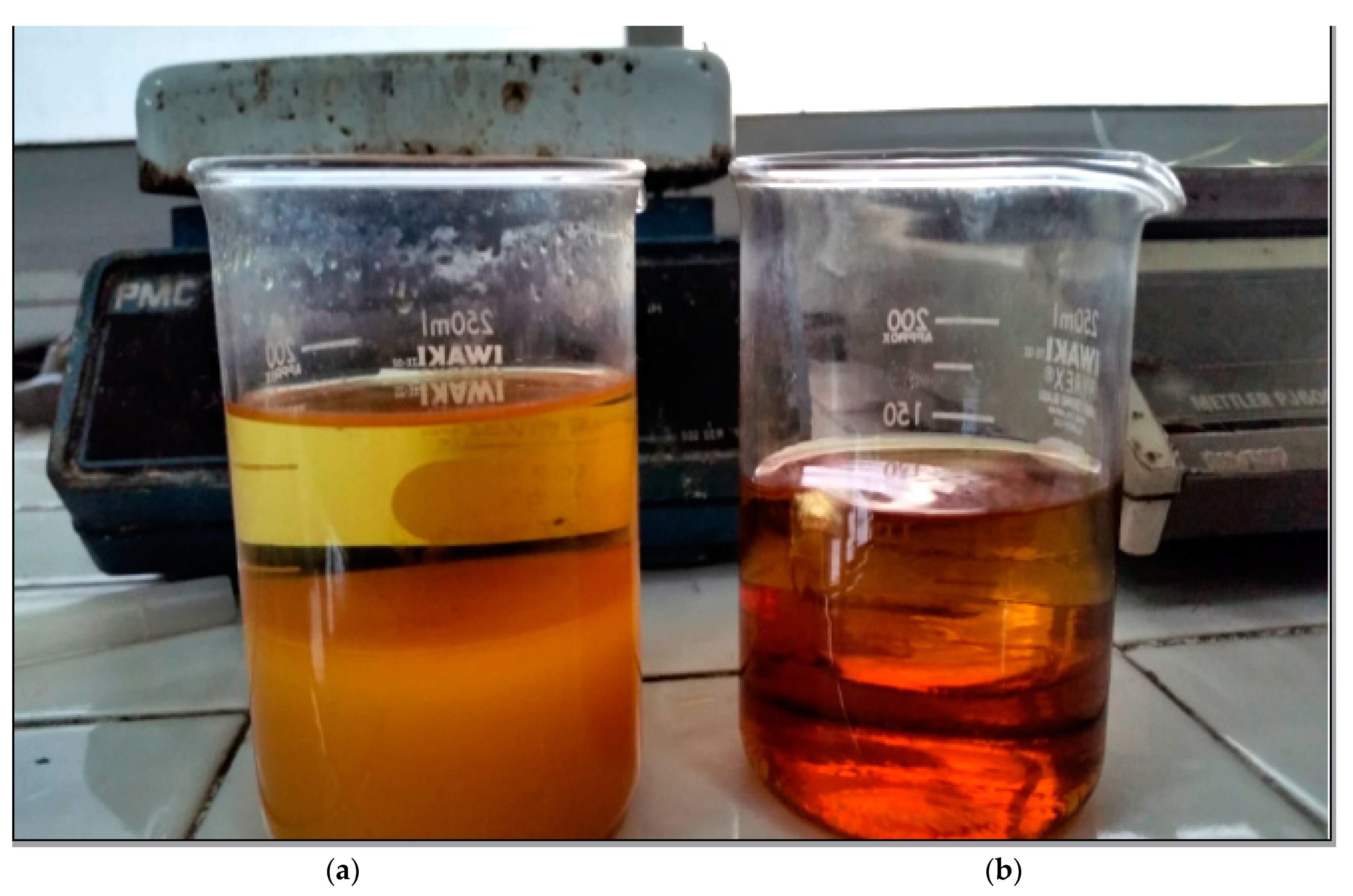
4.1. Testing of Calophyllum-Inophyllum Oil
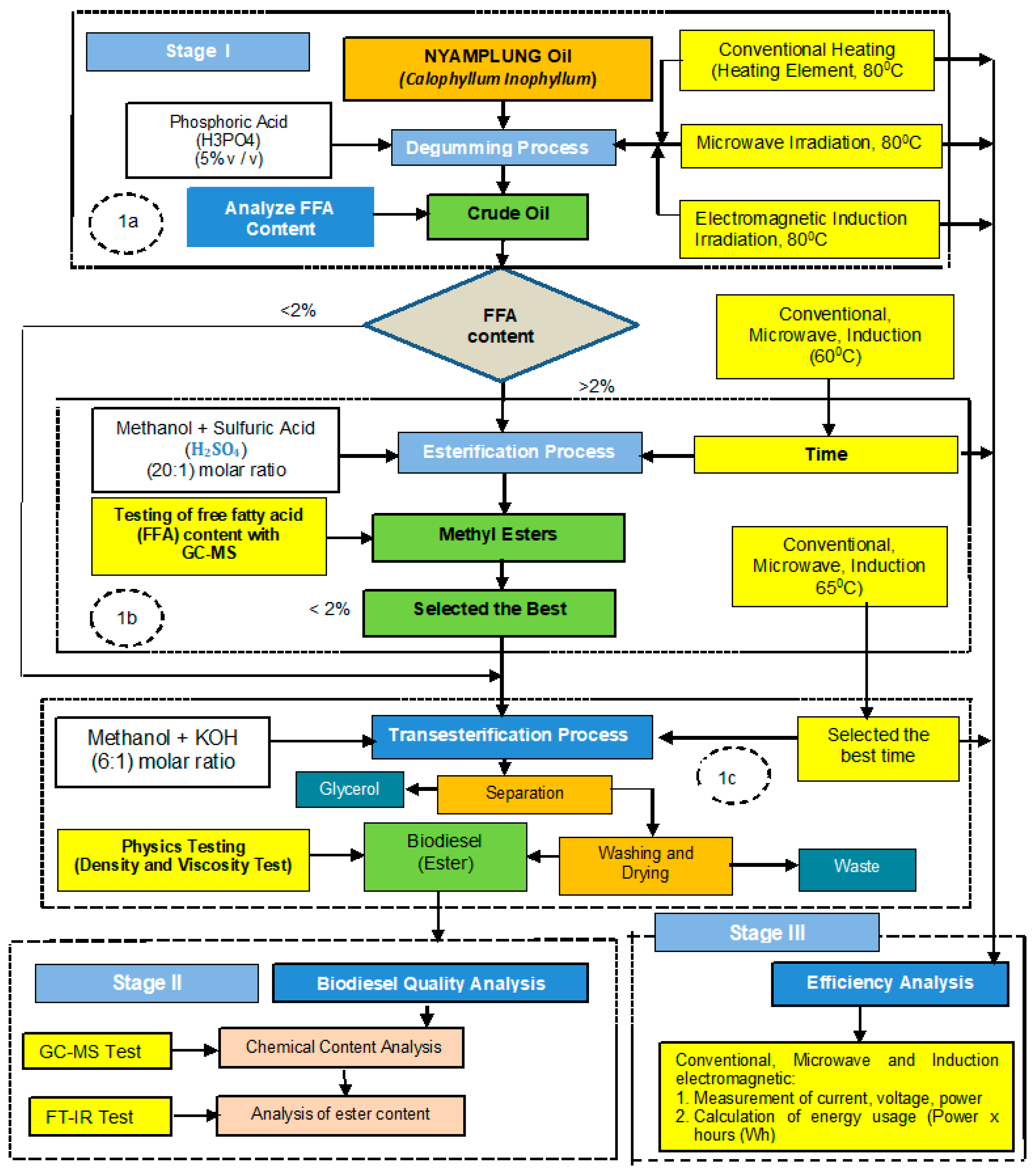
4.2. Biodiesel Processing
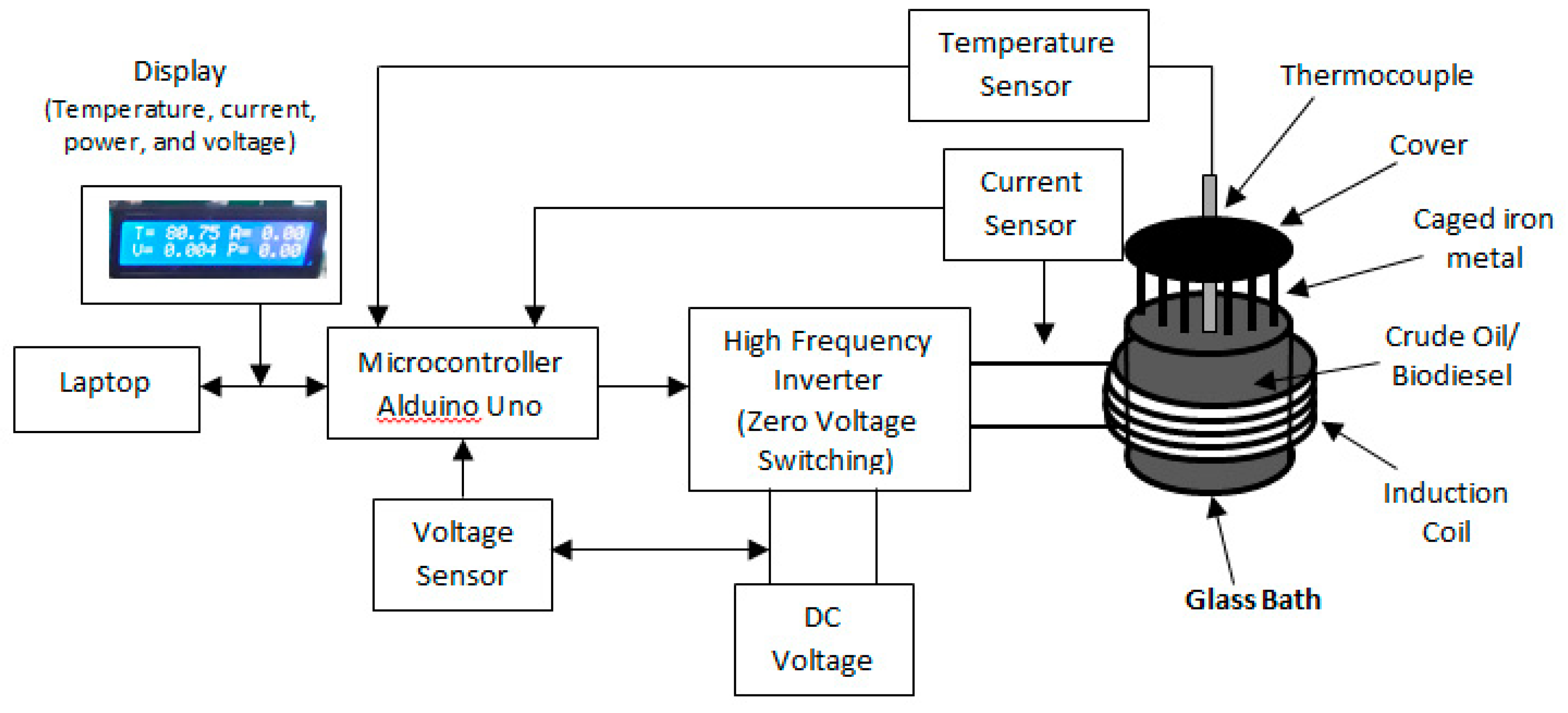
4.3. Induction Heating Irradiation
5. Result
5.1. Characteristics of IH Irradiation
5.2. Advantages of Electromagnetic Induction Methods
5.3. Analysis Free Fatty Acid (FFA)
5.3.1. Esterification Process
5.3.2. Transesterification Process
5.4. Analysis of Energy Use
5.5. Testing of Viscosity and Density
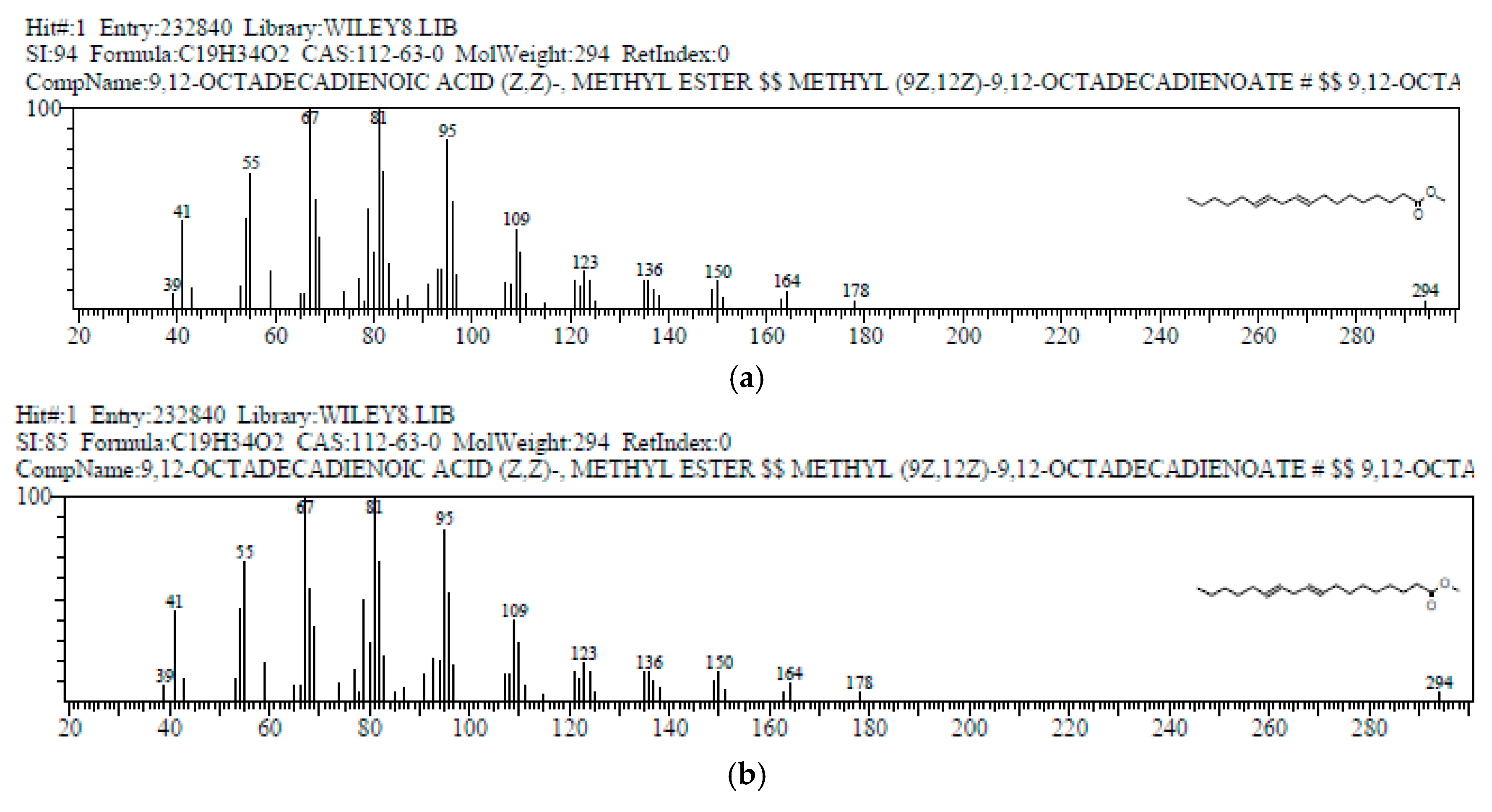
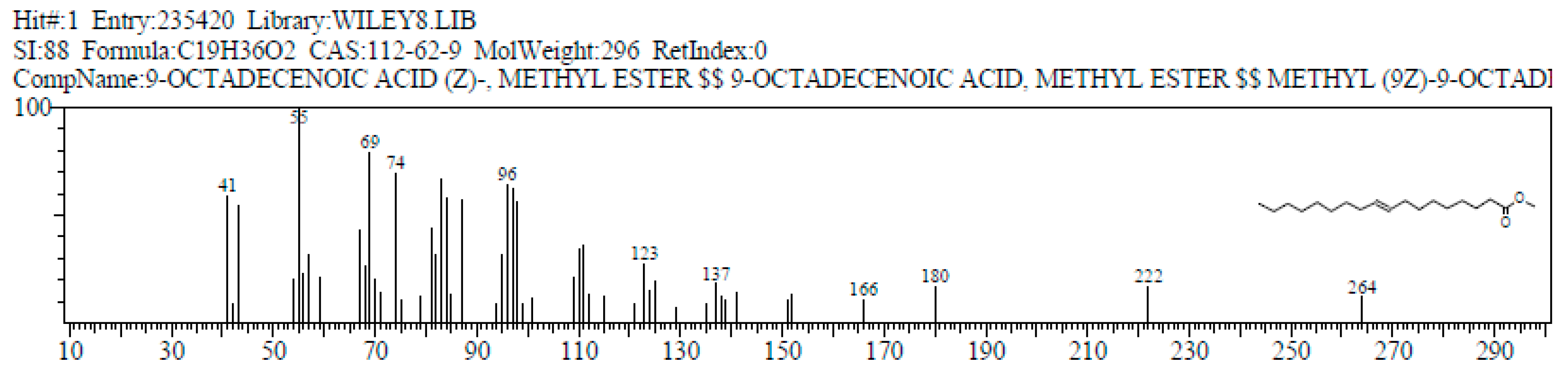
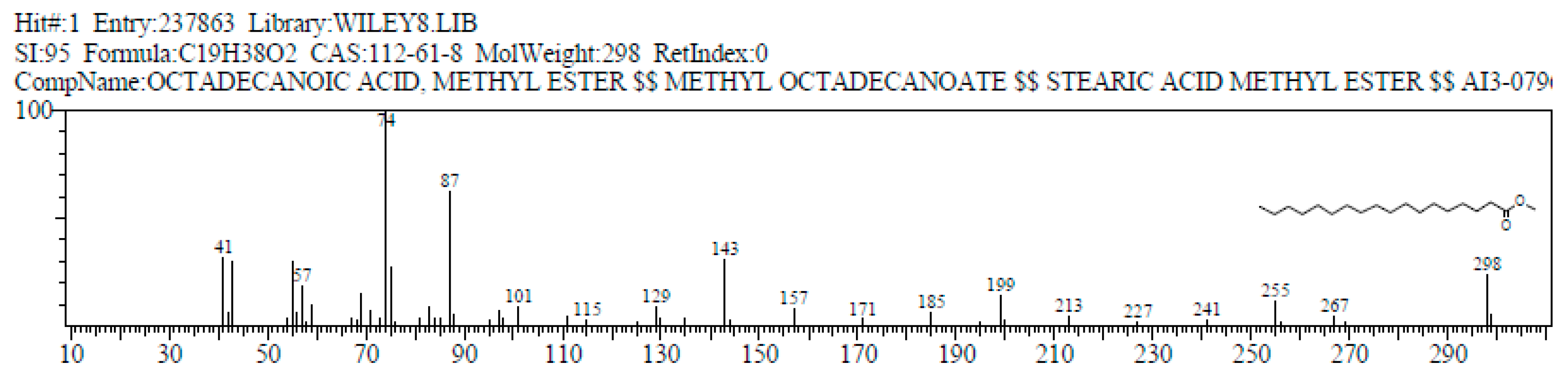
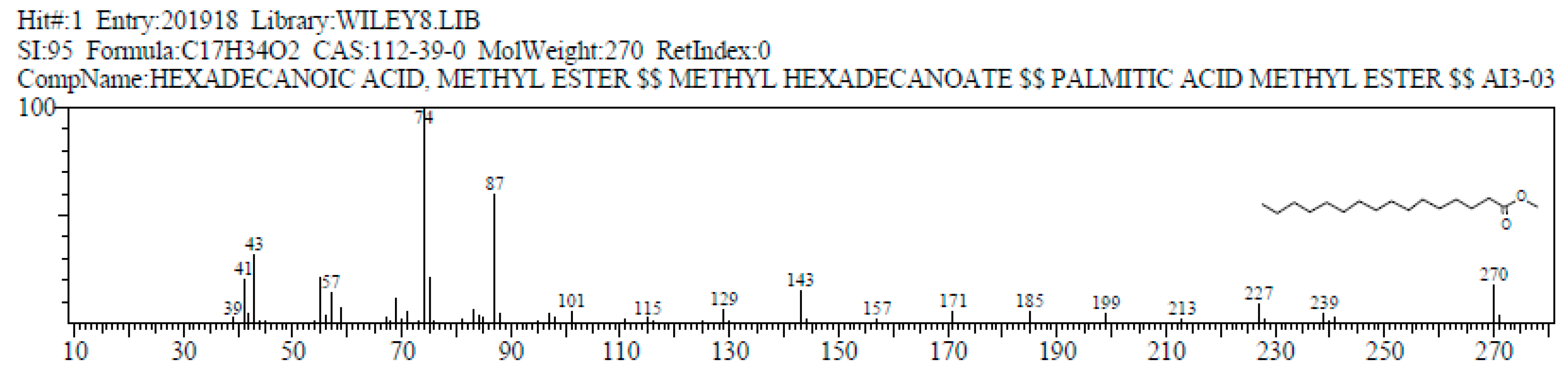
5.6. GC-MS Analysis
6. Discussion
7. Conclusions
- Biodiesel produced from Calophyllum inophyllum oil with electromagnetic induction radiation generally meets ASTM D6751, C1 biodiesel, EN 14214, and SNI standards, so it can be used as an alternative for biodiesel processing.
- Under optimal conditions, the energy consumption of electromagnetic induction is more efficient than the hotplate and microwave method. Compared to heating both hotplate and microwave, the reaction time is significantly reduced.
- Due to having faster reaction time in the transesterification process, the FAME value obtained is higher than the hotplate and microwave. The optimal condition for this experiment is the molar ratio of methanol to oil 6:1, 2% (b/b) of KOH catalyst, a reaction temperature of 65 °C, the reaction time of 0.43 min, and FAME of 65.96%.
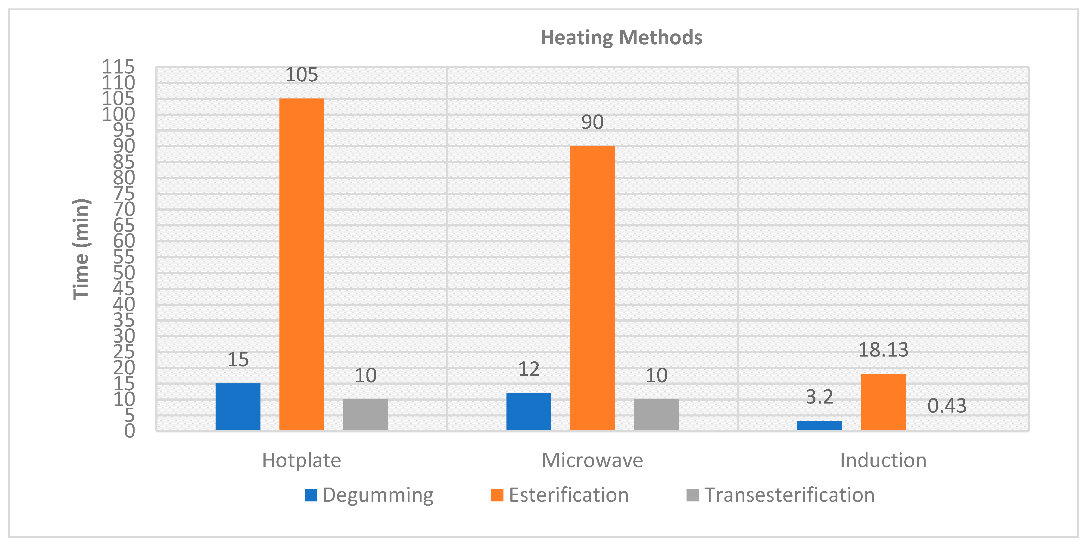
- Compared to microwaves and hotplate, electromagnetic induction is achieved at a shorter time in all stages of degumming, esterification, and transesterification. Overall, the time needed to process biodiesel is hotplate (130 min), microwave (112 min), and electromagnetic induction (21.93 min). As a result, the overall energy used from the biodiesel production stage is also more economical and efficient.
Author Contributions
Funding
Acknowledgments
Conflicts of Interest
References
- Melero, J.A.; Bautista, L.F.; Morales, G.; Iglesias, J.; Sánchez-Vázquez, R. Biodiesel production from crude palm oil using sulfonic acid-modified mesostructured catalysts. Chem. Eng. J. 2009, in press. [Google Scholar] [CrossRef]
- Alkabbashi, A.N.; Alam, M.Z.; Mirghani, M.E.S.; Al-Fusaiel, A.M.A. Biodiesel production from crude palm oil by transesterification process. J. Appl. Sci. 2009, 9, 3166–3170. [Google Scholar] [CrossRef]
- Crabbe, E.; Nolasco-Hipolito, C.; Kobayashi, G.; Sonomoto, K.; Ishizaki, A. Biodiesel production from crude palm oil and evaluation of butanol extraction and fuel properties. Process Biochem. 2001, 37, 65–71. [Google Scholar] [CrossRef]
- Harsono, S.S. Biodiesel production from palm oil technology. Res. J. Agric. Sci. 2011, 43, 80–85. [Google Scholar]
- Kaieda, M.; Samukawa, T.; Matsumoto, T.; Ban, K.; Kondo, A.; Shimada, Y.; Noda, H.; Nomoto, F.; Ohtsuka, K.; Izumoto, E.; et al. Biodiesel fuel production from plant oil catalyzed by Rhizopus oryzae lipase in a water-containing system biofuel’s engineering process technology without an organic solvent. J. Biosci. Bioeng. 1999, 88, 627–631. [Google Scholar] [CrossRef]
- Samukawa, T.; Kaieda, M.; Matsumoto, T.; Ban, K.; Kondo, A.; Shimada, Y.; Noda, H.; Fukuda, H. Pretreatment of immobilized candida antarctica lipase for biodiesel fuel production from plant oil. J. Biosci. Bioeng. 2000, 90, 180–183. [Google Scholar] [CrossRef]
- Silva, C.C.C.M.; Ribeiro, N.F.P.; Souza, M.M.V.M.; Aranda, D.A.G. Biodiesel production from soybean oil and methanol using hydrotalcites as catalyst. Fuel Process. Technol. 2010, 91, 205–210. [Google Scholar] [CrossRef]
- Cao, W.; Han, H.; Zhang, J. Preparation of biodiesel from soybean oil using supercritical methanol and co-solvent. Fuel 2005, 84, 347–351. [Google Scholar] [CrossRef]
- Lee, J.H.; Kwon, C.H.; Kang, J.W.; Park, C.; Tae, B.; Kim, S.W. Biodiesel production from various oils under supercritical fluid conditions by candida antarctica lipase B using a stepwise reaction method. Appl. Biochem. Biotechnol. 2009, 156, 454–464. [Google Scholar] [CrossRef]
- Yu, D.; Tian, L.; Wu, H.; Wang, S.; Wang, Y.; Ma, D.; Fang, X. Ultrasonic irradiation with vibration for biodiesel production from soybean oil by Novozym. Process Biochem. 2010, 45, 519–525. [Google Scholar] [CrossRef]
- Chen, C.-H.; Chen, W.-H.; Chang, C.-M.J.; Lai, S.-M.; Tu, C.-H. Biodiesel production from supercritical carbon dioxide extracted Jatropha oil using subcritical hydrolysis and supercritical methylation. J. Supercrit. Fluids 2010, 52, 228–234. [Google Scholar] [CrossRef]
- Chena, C.-R.; Cheng, Y.-J.; Ching, Y.-C.; Hsiang, D.; Chang, C.-M. Green production of energetic Jatropha oil from de-shelled Jatropha curcas L. seeds using supercritical carbon dioxide extraction. J. Supercrit. Fluids. 2012, 66, 137–143. [Google Scholar] [CrossRef]
- Koh, M.Y.; Ghazi, T.I.M. A review of biodiesel production from Jatropha curcas L. oil. Renew. Sustain. Energy Rev. 2011, 15, 2240–2251. [Google Scholar] [CrossRef]
- Syam, A.M.; Resul, M.F.M.G.; Yunus, R.; Ghazi, T.I.M. Reduction of free fatty acids in crude jatropha curcas oil via an esterification process. Int. J. Eng. Technol. 2008, 5, 92–98. [Google Scholar]
- Shah, S.; Gupta, M.N. Lipase catalyzed preparation of biodiesel from Jatropha oil in a solvent free system. Process Biochem. 2007, 42, 409–414. [Google Scholar] [CrossRef]
- Jain, S.; Sharma, M.P. Prospects of biodiesel from Jatropha in India: A review. Renew. Sustain. Energy Rev. 2010, 14, 763–771. [Google Scholar] [CrossRef]
- Lu, H.; Liu, Y.; Zhou, H.; Yang, Y.; Chen, M.; Liang, B. Production of biodiesel from Jatropha curcas L. oil. Comput. Chem. Eng. 2009, 33, 1091–1096. [Google Scholar] [CrossRef]
- Tiwari, A.K.; Kumar, A.; Raheman, H. Biodiesel production from jatropha oil (Jatropha curcas) with high free fatty acids: An optimized process. Biomass Bioenergy 2007, 31, 569–575. [Google Scholar] [CrossRef]
- Berchmans, H.J.; Hirata, S. Biodiesel production from crude Jatropha curcas L. seed oil with a high content of free fatty acids. Bioresour. Technol. 2008, 99, 1716–1721. [Google Scholar] [CrossRef]
- Köse, Ö.; Tüter, M.; Aksoy, H.A. Immobilized candida antarctica lipase-catalyzed alcoholysis of cotton seed oil in a solvent-free medium. Bioresour. Technol. 2002, 83, 125–129. [Google Scholar] [CrossRef]
- He, C.; Baoxiang, P.; Dezheng, W.; Jinfu, W. Biodiesel production by the transesterification of cottonseed oil by solid acid catalysts. Front. Chem. Eng. China 2007, 1, 11–15. [Google Scholar]
- Royon, D.; Daz, M.; Ellenrieder, G.; Locatelli, S. Enzymatic production of biodiesel from cotton seed oil using t-butanol as a solvent. Bioresour. Technol. 2007, 98, 648–653. [Google Scholar] [CrossRef]
- Hoda, N. Optimization of biodiesel production from cottonseed oil by transesterification using NaOH and methanol. Energy Sourcespart A Recoveryutilizationand Environ. Eff. 2010, 32, 434–441. [Google Scholar] [CrossRef]
- Azcan, N.; Danisman, A. Alkali catalyzed transesterification of cottonseed oil by microwave irradiation. Fuel 2007, 86, 2639–2644. [Google Scholar] [CrossRef]
- Rashid, U.; Anwar, F.; Knothe, G. Evaluation of biodiesel obtained from cottonseed oil. Fuel Process. Technol. 2009, 90, 1157–1163. [Google Scholar] [CrossRef]
- Su, C.; Nguyen, H.C.; Pham, U.K.; Nguyen, M.L.; Juan, H.-Y. Biodiesel production from a novel nonedible feedstock, soursop (Annona muricata L.) seed oil. Energies 2018, 11, 2562. [Google Scholar] [CrossRef]
- Demirbaş, A. Biodiesel from waste cooking oil via base-catalytic and supercritical methanol transesterification. Energy Convers. Manag. 2009, 50, 923–927. [Google Scholar] [CrossRef]
- Zhang, Y.; Dube, M.A.; McLean, D.D.; Kates, M. Biodiesel production from waste cooking oil: Process design and technological assessment. Bioresour. Technol. 2003, 89, 1–16. [Google Scholar] [CrossRef]
- Issariyakul, T.; Kulkarni, M.G.; Meher, L.C.; Dalai, A.K.; Bakhshi, N.N. Biodiesel production from mixtures of canola oil and used cooking oil. Chem. Eng. J. 2008, 140, 77–85. [Google Scholar] [CrossRef]
- Bobadilla, M.C.; Lorza, R.L.; García, R.E.; Gómez, F.S.; González, E.P.V. An improvement in biodiesel production from waste cooking oil by applying thought multi-response surface methodology using desirability functions. Energies 2017, 10, 130. [Google Scholar] [CrossRef]
- Da Cunha, M.E.; Krause, L.C.; Moraes, M.S.A.; Faccini, C.S.; Jacques, R.A.; Almeida, S.R.; Rodrigues, M.R.A.; Caramão, E.B. Beef tallow biodiesel produced in a pilot scale. Fuel Process. Technol. 2009, 90, 570–575. [Google Scholar] [CrossRef]
- Chung, K.H.; Kim, J.; Lee, K.Y. Biodiesel production by transesterification of duck tallow with methanol on alkali catalysts. Biomass Bioenergy 2009, 33, 155–158. [Google Scholar] [CrossRef]
- Gürü, M.; Artukoğlu, B.D.; Keskin, A.; Koca, A. Biodiesel production from waste animal fat and improvement of its characteristics by synthesized nickel and magnesium additive. Energy Convers. Manag. 2009, 50, 498–502. [Google Scholar] [CrossRef]
- Gürü, M.; Koca, A.; Can, Ö.; Cınar, C.; Şahin, F. Biodiesel production from waste chicken fat-based sources and evaluation with Mg based additive in a diesel engine. Renew. Energy 2010, 35, 637–643. [Google Scholar] [CrossRef]
- Tashtoush, G.M.; Al-Widyan, M.I.; Al-Jarrah, M.M. Experimental study on evaluation and optimization of conversion of waste animal fat into biodiesel. Energy Convers. Manag. 2004, 45, 2697–2711. [Google Scholar] [CrossRef]
- Öner, C.; Altun, Ş. Biodiesel production from inedible animal tallow and an experimental investigation of its use as alternative fuel in a direct injection diesel engine. Appl. Energy 2009, 86, 2114–2120. [Google Scholar] [CrossRef]
- Knothe, G.; Razon, L.F.; Bacani, F.T. Kenaf oil methyl esters. Ind. Crop. Prod. 2013, 49, 568–572. [Google Scholar] [CrossRef]
- Lam, M.K.; Lee, K.T. Mixed methanol-ethanol technology to produce greener biodiesel from waste cooking oil: A breakthrough for SO4 2 −/SnO2–SiO2 catalyst. Fuel Process. Technol. 2011, 92, 1639–1645. [Google Scholar] [CrossRef]
- Paraschivescu, M.C.; Alley, E.G.; French, W.T.; Hernandez, R.; Armbrust, K. Determination of methanol in biodiesel by headspace solid phase microextraction. Bioresour. Technol. 2008, 99, 5901–5905. [Google Scholar] [CrossRef]
- Joker, D. Calophyllum inophyllum L. Seed Leaflet; No 87; Forest & Landscape Denmark: Hørsholm, Denmark, 2004. [Google Scholar]
- Anonim. Anonim. Nyamplung Plant-Based Alternative Energy Development Plan 2010–2014. Ministry of Forestry Republic of Indonesia, 2008. Available online: https://anzdoc.com/draft-rencana-aksi-pengembangan-energi-alternatif-berbasis-t.html (accessed on 30 December 2013). (In Indonesia).
- Said, T.; Dutot, M.; Martin, C.; Beaudeux, J.L.; Boucher, C.; Enee, E. Cytoprotective effect against UV-induced DNA damage and oxidative stress: Role of new biological UV filter. Eur. J. Pharm. Sci. 2007, 30, 203–210. [Google Scholar] [CrossRef]
- Dweek, A.C.; Meadows, T. Tamanu (Calophyllum inophyllum L.) the Africa, Asia Polynesia & Pasific Panacea. Int. J. Cosmet. Sci. 2002, 24, 341–348. [Google Scholar]
- Kraftiadi, S. Energy Analysis on Nyamplung Oil Making Process; Department of Agricultural Engineering, Faculty of Agriculture, Bogor Agricultural Institute: Bogor, Indonesia, 2011. (In Indonesia) [Google Scholar]
- Fathiyah, S. Study Process of Oil Purification Nyamplung as Biofuels; Department of Industrial Technology of Agriculture, Faculty of Agricultural Technology, Bogor Agricultural University: Bogor, Indonesia, 2010. (In Indonesia) [Google Scholar]
- Motasemi, F.; Ani, F.N. A review on microwave-assisted production of biodiesel. Renew. Sustain. Energy Rev. 2012, 16, 4719–4733. [Google Scholar] [CrossRef]
- Hsiao, M.-C.; Hou, S.-S.; Kuo, J.-Y.; Hsieh, P.-H. Optimized conversion of waste cooking oil to biodiesel using calcium methoxide as catalyst under homogenizer system conditions. Energies 2018, 11, 2622. [Google Scholar] [CrossRef]
- Hernando, J.; Letón, P.; Matia, M.; Novella, J.; Alvarez-Builla, J. Biodiesel and FAME synthesis assisted microwave: Homogenous batch and flow process. Fuel 2007, 86, 1644–1646. [Google Scholar] [CrossRef]
- Wu, L.; Zhu, H.; Huang, K. Thermal analysis on the process of microwave-assisted biodiesel production. Bioresour. Technol. 2013, 133, 279–284. [Google Scholar] [CrossRef]
- Barnard, T.M.; Leadbeater, N.E.; Boucher, M.B.; Stencel, L.M.; Wilhite, B.A. Continuous flow preparation of biodiesel using microwave heating. Energy Fuel 2007, 21, 1777–1781. [Google Scholar] [CrossRef]
- Saifuddin, N.; Chua, K.H. Production of ethyl ester (biodiesel) from used frying oil: Optimization of transesterification process using microwave irradiation. Malays. J. Chem. 2004, 6, 77–82. [Google Scholar]
- Haryanto, A.; Silviana, U.; Triyono, S.; Prabawa, S. Biodiesel production from transesterification of waste cooking oil with the assistance of micro waves: The effect of power intensity and reaction time on rendement and biodiesel characteristics. Agritech 2015, 35. (In Indonesia) [Google Scholar]
- Chen, K.-S.; Lin, Y.-C.; Hsu, K.-H.; Wang, H.-K. Improving biodiesel yields from waste cooking oil by using sodium methoxide and a microwave heating system. Energy 2012, 38, 151–156. [Google Scholar] [CrossRef]
- Lertsathapornsuk, V.; Ruangying, P.; Pairintra, R.; Krisnangkura, K. Continuous Transethylation of Vegetable Oils by Microwave Irradiation. In Proceedings of the First Thai Energy Network Academic Conference Ambassador of Jomtien City, Chon Buri, Bangkok, 11–13 May 2005; pp. RE11-1–RE11-4. [Google Scholar]
- Sherbiny, S.A.E.; Refaat, A.A.; Sheltawy, S.T.E. Production of biodiesel using the microwave technique. J. Adv. Res. 2010, 1, 309–314. [Google Scholar] [CrossRef]
- Anonim. Induction Heating System Topology Review. 2000. Available online: www.fairchildsemi.com (accessed on 5 September 2016).
- Lucia, O.; Maussion, P.; Dede, E.J.; Burdio, J. Induction heating technology and its applications: Past developments, current technology, and future challenges. Ieee Trans. Ind. Electron. 2013, 6, 2509–2520. [Google Scholar] [CrossRef]
- Koertzen, H.W.; Ferreira, J.A.; van Wyk, J.D. A comparative study of single switch induction heating converters using novel component effectivity concepts. In Proceedings of the IEEE Power Electronics Specialists Conference, Toledo, Spain, 29 June–3 July 1992; pp. 298–305. [Google Scholar]
- Dede, E.J.; Gonzalez, J.V.; Linares, J.A.; Jordan, J.; Ramirez, D.; Rueda, P. 25-kW/50-kHz generator for induction heating. Ieee Trans. Ind. Electron. 1991, 38, 203–209. [Google Scholar] [CrossRef]
- Koertzen, H.W.; Wyk, J.D.V.; Ferreira, J.A. Design of the half-bridge series resonant converters for induction cooking. In Proceedings of the IEEE Power Electronics Specialist Conference Records, Atlanta, GA, USA, 18–22 June 1995; pp. 729–735. [Google Scholar]
- Kamli, M.; Yamamoto, S.; Abe, M. A 50–150 kHz half-bridge inverter for induction heating applications. Ieee Trans. Ind. Electron. 1996, 43, 163–172. [Google Scholar] [CrossRef]
- Rezon, A. Half Bridge Inverter Design for Induction Heater Power Supply in Plastic Etruder Tool; University of Diponegoro: Semarang, Indonesia, 2013. (In Indonesia) [Google Scholar]
- Lozinski, M.G. Industrial Application of Induction Heating; Pergoman Press: London, UK, 1969. [Google Scholar]
- Emil, A.; Yaakob, Z.; Kumar, M.S.; Jahim, J.M.; Salimon, J. Comparative evaluation of physicochemical properties of Jatropha seed oil from Malaysia, Indonesia and Thailand. J. Am. Oil Chem. Soc. 2010, 87, 689–695. [Google Scholar] [CrossRef]
- Hsiao, M.-C.; Kuo, J.-Y.; Hsieh, P.-H.; Hou, S.-S. Improving biodiesel conversions from blends of high- and low-acid-value waste cooking oils using sodium methoxide as a catalyst based on a high-speed homogenizer. Energies 2018, 11, 2298. [Google Scholar] [CrossRef]
- Huppertz, T. Homogenization of milk other types of homogenizer (high-speed mixing, ultrasonics, microfluidizers, membrane emulsification). Encycl. Dairy Sci. 2011, 761–764. [Google Scholar]
- Håkansson, A.; Trägårdh, C.; Bergenståhl, B. Studying the effects of adsorption, recoalescence and fragmentation in a high-pressure homogenizer using a dynamic simulation model. Food Hydrocoll. 2009, 23, 1177–1183. [Google Scholar] [CrossRef]
- Ghorbani, A.; Rahimpour, M.R.; Ghasemi, Y.; Raeissi, S. The biodiesel of microalgae as a solution for diesel demand in Iran. Energies 2018, 11, 950. [Google Scholar] [CrossRef]
- Hayyan, A.; Alam, M.Z.; Mirghani, M.E.; Kabbashi, N.A.; Hakimi, N.I.N.M.; Siran, Y.M.; Tahiruddin, S. Reduction of high content of free fatty acid in sludge palm oil via acid catalyst for biodiesel production. Fuel Process. Technol. 2011, 92, 920–924. [Google Scholar] [CrossRef]
- Çayl, G.; Küsefoglu, S. Increased yields in biodiesel production from used cooking oils by a two-step process: Comparison with one step process by using TGA. Fuel Process. Technol. 2008, 89, 118–122. [Google Scholar] [CrossRef]
- Refaat, A.A.; Attia, N.K.; Sibak, H.A.; El Sheltawy, S.T.; ElDiwani, G.I. Production optimization and quality assessment of biodiesel from waste vegetable oil. Int. J. Environ. Sci. Technol. 2008, 5, 75–82. [Google Scholar] [CrossRef]
- Dmytryshyn, S.L.; Dalai, A.K.; Chaudhari, S.T.; Mishra, H.K.; Reaney, M.J. Synthesis and characterization of vegetable oil derived esters: Evaluation for their diesel additive properties. Bioresour. Technol. 2004, 92, 55–64. [Google Scholar] [CrossRef] [PubMed]
- Vicente, G.; Martinez, M.; Aracil, J. Integrated biodiesel production: A comparison of different homogeneous catalysts systems. Bioresour. Technol. 2004, 92, 297–305. [Google Scholar] [CrossRef] [PubMed]
- Özçimen, D.; Yücel, S. Biofuel’s Engineering Process Technology; Yıldız Technical University, Bioengineering Department: Istanbul, Turkey, 1969; Volume 742, ISBN 978-953-307-480-1. [Google Scholar]
- Kapilan, N.; Baykov, B.D. A review on new methods used for the production of biodiesel. Coal Pet. Coal 2014, 56, 62–73. [Google Scholar]
- Sapiuddin, N.; Samiuddin, A.; Kumaran, P. A review on processing for biodiesel production. Trends Appl. Sci. Res. 2015, 10, 1–37. [Google Scholar]


| Methods | Temperature | Time | Power | FFA (%) | FFA (%) |
|---|---|---|---|---|---|
| (°C) | (Min) | (W) | Before | After | |
| Hotplate | 80 | 15 | 600 | 20.27 | 17.66 |
| Microwave | 80 | 12 | 120 | 19.82 | 17.21 |
| Electromagnetic Induction | 80 | 3.21 | 145 | 19.7 | 17.03 |
| No. | Name | Specification |
|---|---|---|
| 1. | Dc Voltage | 30 Volts |
| 2. | Power Input | 200 watts |
| 3. | Current Output | 1.2 Amps |
| 4. | Temperature | 0–1000 °C (adjustable) |
| Method | Temperature (°C) | Esterfication I | Esterification II | ||
|---|---|---|---|---|---|
| Time (Min) | FFA (I) (%) | Time (Min) | FFA (II) (%) | ||
| Hotplate | 60 | 75 | 6.8 | 30 | 1.7 |
| Microwave | 60 | 75 | 3.59 | 15 | 1.43 |
| Induction Electromagnetic | 60 | 12 | 5.8 | 6.13 | 1.6 |
| Method | Temperature (°C) | Time (Min) | FFA (%) | FAME (%) |
|---|---|---|---|---|
| Hotplate | 65 | 10 | 0.56 | 35,1 |
| Microwave | 65 | 10 | 0.42 | 53.66 |
| Induction Electromagnetic | 65 | 0.43 | 0.4 | 65.96 |
| Methods | Energy Consumption (Wh) | Total Energy (Wh) | ||
|---|---|---|---|---|
| Degumming | Esterification | Transesterification | ||
| Hotplate | 150 | 900 | 96 | 1.146 |
| Microwave | 19.2 | 50 | 6.4 | 75.6 |
| Electromagnetic Induction | 7.68 | 38.7 | 0.91 | 47.29 |
| Properties | ASTM D6751 (USA) | ASTM PS 121 | EN 14214 | C1 Biodiesel | SNI | Nyamplung Biodiesel |
|---|---|---|---|---|---|---|
| (This Study) | ||||||
| Acid value (mg KOH/g) | <0.5 | <0.5 | <0.5 | 0.34 | 0.8 | 0.8 |
| Density (20 C) (g/mL) | 0.87–0.9 | 0.7328 | No specific | 0.877 | 0.850–0.890 | 0.882 |
| Kinematic viscosity, 40 °C (mm2/s) | 1.9–6.0 | 1.9–6.0 | 3.5–5.0 | 5.6872 | 2.3–6.0 | 5.54 |
| Component | Peak | Detection Time | Identified Compounds | Molecular Formula | Percentage (%) |
|---|---|---|---|---|---|
| I. | 6 7 | 35.006 35.109 | Linoleic acid methyl ester | C19H34O2C19H34O2 | 16.78 + 17.17 = 33.95 |
| II. | 8 | 35.388 | Oleic acid methyl ester | C19H36O2 | 20.06 |
| III. | 9 | 35.997 | Stearic acid methyl ester | C19H38O2 | 18.62 |
| IV. | 3 | 28.563 | Palmitic acid methyl ester | C17H34O2 | 17.12 |
© 2019 by the authors. Licensee MDPI, Basel, Switzerland. This article is an open access article distributed under the terms and conditions of the Creative Commons Attribution (CC BY) license (http://creativecommons.org/licenses/by/4.0/).
Share and Cite
Kurniati, S.; Soeparman, S.; Yuwono, S.S.; Hakim, L.; Syam, S. A Novel Process for Production of Calophyllum Inophyllum Biodiesel with Electromagnetic Induction. Energies 2019, 12, 383. https://doi.org/10.3390/en12030383
Kurniati S, Soeparman S, Yuwono SS, Hakim L, Syam S. A Novel Process for Production of Calophyllum Inophyllum Biodiesel with Electromagnetic Induction. Energies. 2019; 12(3):383. https://doi.org/10.3390/en12030383
Chicago/Turabian StyleKurniati, Sri, Sudjito Soeparman, Sudarminto Setyo Yuwono, Lukman Hakim, and Sudirman Syam. 2019. "A Novel Process for Production of Calophyllum Inophyllum Biodiesel with Electromagnetic Induction" Energies 12, no. 3: 383. https://doi.org/10.3390/en12030383