Article

High Frequency Square-Wave Voltage Injection Scheme-Based Position Sensorless Control of IPMSM in the Low- and Zero- Speed Range

School of Mechatronic Engineering and Automation, Shanghai University, Baoshan District, Shanghai 200444, China
*
Author to whom correspondence should be addressed.
Energies 2019, 12(24), 4776; https://doi.org/10.3390/en12244776
Submission received: 5 November 2019 / Revised: 7 December 2019 / Accepted: 12 December 2019 / Published: 14 December 2019
(This article belongs to the Special Issue Advances in Rotating Electric Machines)

Abstract

:
In this paper, a new sensorless control scheme with the injection of a high-frequency square-wave voltage of an interior permanent-magnet synchronous motor (IPMSM) at low- and zero-speed operation is proposed. Conventional schemes may face the problems of obvious current sampling noise and slow identification in the process of magnetic polarity detection at zero speed operation, and the effects of inverter voltage error on the rotor position estimation accuracy at low speed operation. Based on the principle analysis of d-axis magnetic circuit characteristics, a method for determining the direction of magnetic polarity of d-axis two-opposite DC voltage offset by uninterruptible square-wave injection is proposed, which is fast in convergence rate of magnetic polarity detection and more distinct. In addition, the strategy injects a two-opposite high-frequency square-wave voltage vectors other than the one voltage vector into the estimated synchronous reference frame (SRF), which can reduce the effects of inverter voltage error on the rotor position estimation accuracy. With this approach, low-pass filter (LPF) and band-pass filter (BPF), which are used to obtain the fundamental current component and high-frequency current response with rotor position information respectively in the conventional sensorless control, are removed to simplify the signal process for estimating the rotor position and further improve control bandwidth. Finally, the experimental results on an IPMSM drive platform indicate that the rotor position with good steady state and dynamic performance can be obtained accurately at low-and zero-speed operation with the sensorless control strategy.

Graphical Abstract

1. Introduction

Permanent-magnet synchronous motors (PMSMs) have been widely applied in industrial fields [1,2,3,4] for the excellent features of high reliability, high efficiency, high torque density, good dynamic performance, etc. According to the structure of the permanent magnet of the rotor, the PMSM can be divided into interior permanent-magnet synchronous motor (IPMSM) and surface-mounted permanent-magnet synchronous motor (SPMSM). Compared with the SPMSM, the IPMSMs have attracted much attention in industrial fields recently due to their greatly improved overload capacity, power density and speed regulation range, which ascribes to the permanent magnet of the IPMSM is located inside the rotor.
To take advantage of these features, the information of rotor position acquired generally by the mechanical sensors, i.e., resolver or encoder, is necessarily required when the field-oriented control (FOC) scheme [5,6] is adopted. However, these mechanical sensors [7,8] mounted on the shaft of a PMSM bring several disadvantages such as extra cost, extra volume, low reliability, etc. In order to overcome these disadvantages, various kinds of position-sensorless control strategies that estimate the rotor position information without a mechanical sensor have been proposed in past decades [9,10,11,12]. Conventional sensorless control methods are mainly divided into two groups: (1) For medium- to high-speed operation, the schemes based on the estimation of back electromotive force (EMF), which contains the position information, (2) for low-speed operation, usually under 5% of the rated speed, the schemes based on the machine saliency injects an additional high-frequency (HF) signal to the PMSM which generates a response containing information of the rotor position.
This paper investigates the position-sensorless control strategy using the HF signal injection method in the low- and zero-speed operation, and according to the types of the injected HF signals, the signal can be mainly divided into rotating sinusoidal voltage injection (RSVI) [13], pulsating sinusoidal voltage injection (PSVI) [14], and pulsating square-wave voltage injection (PUVI) [15]. The first HF rotating sinusoidal voltage injection method was proposed by Lorenz R.D in the early time, and in this method, the balanced rotating voltage signals were injected into the stationary reference frame (SRF) and then the induced currents were extracted to obtain the rotor position information. However, this method injects an additional HF voltage into the SRF system, which will lead to the torque ripple caused by the fluctuation of q-axis current. Moreover, the saliency will be reduced under heavy load and the detection accuracy will be worse due to the magnetic saturation effect. For the improvement of the RSVI, pulsating sinusoidal voltage injection and pulsating square-wave voltage injection are proposed, which inject HF voltages in the estimated d-axis of the rotational reference frame (RRF) other than the SRF. To overcome these problems, a PSVI method [16] injects HF voltage into the estimated d-axis reference frame. Similar to RSVI method, the injection voltage frequency of PSVI method is usually about 1/10 of the carrier frequency. Therefore, this method should use low-pass filter (LPF) and band-pass filter (BPF) to separate the fundamental current component and HF currents, respectively, which decreases the control bandwidth and the dynamic performance. To improve the dynamic performance, reference [17] proposed the PUVI method, in which the HF square-wave injected into the estimated d-axis and increased the frequency of the injected signal as high as possible to the pulse width modulation (PWM) carrier frequency. Since the frequency of the injected HF square-wave voltage signal is much higher than the cut-off frequency of current loop, the LPFs in the current feedback loop can be omitted [18], which improves the response speed to some extent. Seung et al. [19] proposed a method that the frequency of the injected HF square-wave voltage signal is the same as the PWM switching frequency, in which two current samples were taken in a square-wave period and three arithmetic operations were performed to obtain the HF induced current signal. Besides, the dynamics of the position-sensorless control can be improved and the acoustic noise can be remarkably reduced. However, this method still needs to use a BPF for obtaining the feedback current signal. In [20], the fundamental current signal of the stator winding is obtained by arithmetic operation, without using a filter, but it is still necessary to sample the current twice in one square-wave period.
The conventional square-wave injection method has many advantages, such as low current noise, high bandwidth, and high steady state performance, etc. However, the voltage error caused by the nonlinearity of the inverter still needs to be taken seriously and solved. In addition, the magnetic polarity detection, which is one of the main problems to be improved, is essential for smooth startup and robust control of IPMSM. The conventional method [21] proposes to detect the initial position of the rotor by pulse voltage vector method, which injects a series of pulse voltage vectors with the same amplitude and different direction into the motor stator winding, and estimates the rotor pole position by comparing the magnitude of the response current based on the nonlinear saturation characteristics of the motor stator core. However, the current amplitude does not change much as the voltage vector approaches the rotor pole position. At the same time, the phase current measurement error and the inverter nonlinearity will affect the measurement accuracy [16].
In order to solve the problem of initial position detection in conventional sensorless control of IPMSM, a rotating voltage injection sensorless method of estimating the initial rotor position of a direct torque controlled IPMSM drive is proposed in [22], which injects a HF voltage to the windings and extracts the amplitude of the corresponding stator current components based on motor salient effect. However, this method still has some problems, such as obvious current sampling noise, influence by motor parameter variations, and special position interference. The improvement of the RSVI, PUVI, which has been proven to be the best injection type for the low- and zero-speed position sensorless control [23], can rarely be found for the initial rotor position detection in the sensorless control system. Xie et al. [24] proposed a PUVI method in which the two opposite voltage vectors were injected to reduce the effects of inverter voltage error on the position estimation accuracy. However, this method only studies the low-speed range, and does not conduct research and analysis on the zero-speed range, especially the lack of research on magnetic polarity detection, which is essential for smooth startup and robust control of IPMSM. In [25], the positive and negative test pulse voltages are injected into the estimated d-axis, and the positive direction of the magnetic polarity is judged by the time when the currents at different magnetic polarity are attenuated from the steady state value to 0. However, the position estimation is stopped in the process of polarity identification, which makes the structure of the code more complicated. This problem also exists in [26] and [27], and the interval of signal injection must be existed, resulting in long execution time and poor stability. Then, [28] uses the difference in current measured at zero time of each PWM period to determine the magnetic polarity. The advantage is that no additional injection voltage is required, and the convergence speed is fast. The disadvantage of this method is that the position estimation depends on the accuracy of the current. Once the current signal-to-noise ratio is too small, the rotor position cannot be accurately obtained. Based on the above references and the improvement points of this article, the comparison of Table 1 is obtained.
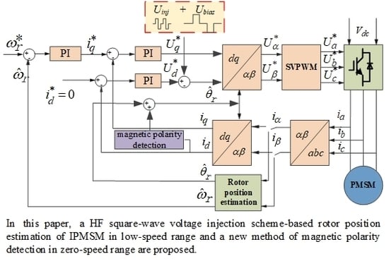
Therefore, in view of the existing sensorless estimation methods for rotor position, a HF square-wave voltage injection scheme-based rotor position estimation of IPMSM in low-speed range and a new method of magnetic polarity detection in zero-speed range are proposed. Based on the principle analysis of d-axis magnetic circuit characteristics, a method for determining the direction of magnetic polarity of d-axis two-opposite DC voltage offset by uninterruptible square-wave injection is proposed, which is simple and can quickly converge by comparing the absolute value of the peak-to-peak value in the d-axis high-frequency current response. Therefore, the method of magnetic polarity identification proposed in this paper is not only suitable for the case where the motor is stationary, but also suitable for the free running condition of the motor. At the same time, the strategy injects a two-opposite HF square-wave voltage vectors into the estimated SRF, which considers the effects of inverter voltage error on the rotor position estimation accuracy. With this approach, the LPF and the BPF are removed to simplify the signal process for estimating the rotor position and further improve control bandwidth.
This paper is organized as follows. First, the rotor position estimation strategy based on conventional HF square-wave voltage injection is analyzed in Section 2. In Section 3, the rotor position estimation strategy based on improved HF square-wave voltage injection and proposed magnetic polarity detection are investigated. Then, in 
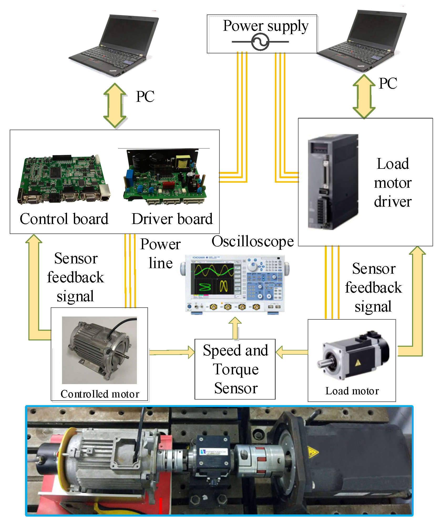
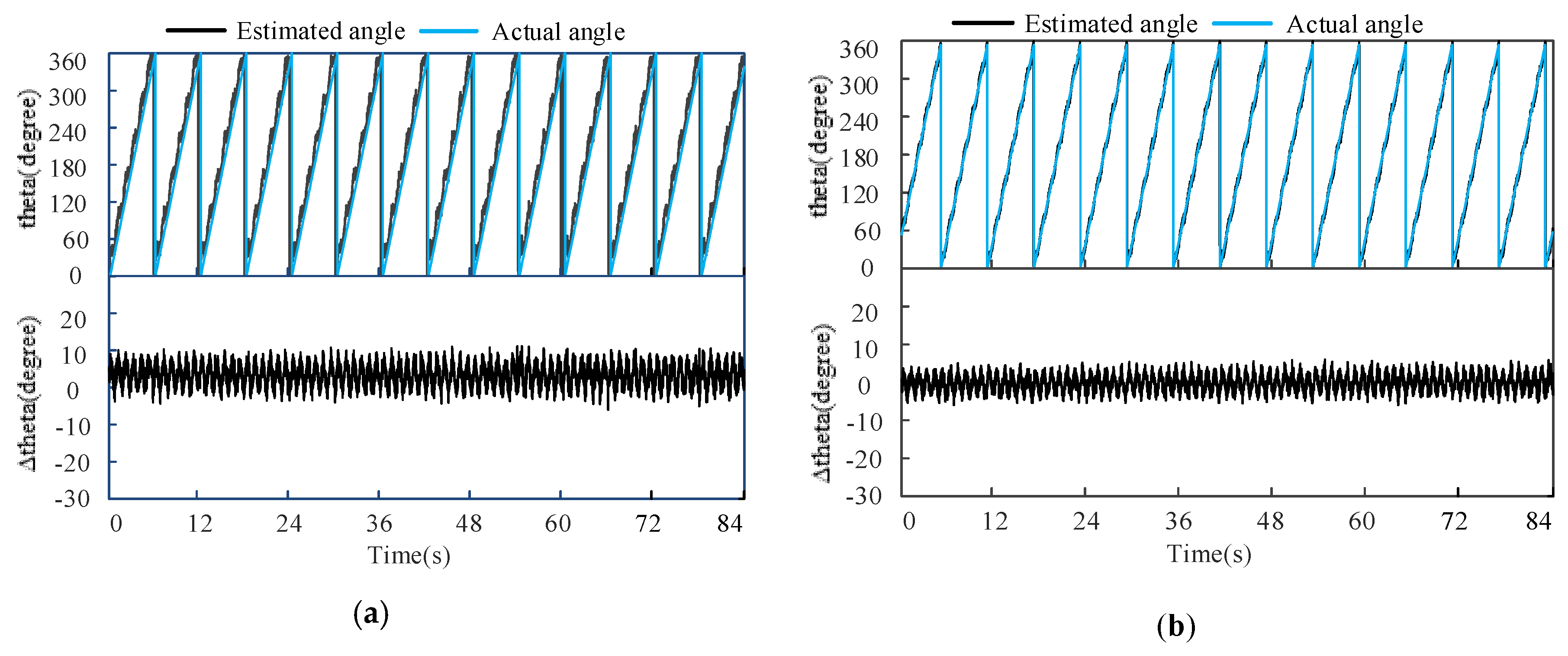
Section 4, comprehensive simulation and experimental setup are introduced and experiments are provided to prove the effectiveness of the improved sensorless control strategy and proposed magnetic polarity detection method. Finally, Section 5 concludes this paper.

2. Analysis of Rotor Position Estimation Strategy Based on Conventional Square-Wave Voltage Injection

2.1. Mathematical Model of IPMSM

Assuming that the IPMSM operates in an unsaturated state with negligible hysteresis loss and eddy current loss, the mathematical model of the IPMSM in the α-β stationary reference frame is given as:
[ u α s u β s ] = R s [ i α s i β s ] + [ L s u m r + L d i f r cos 2 θ r L d i f r sin 2 θ r L d i f r sin 2 θ r L s u m r L d i f r cos θ r ] d d t [ i α s i β s ] + 2 L d i f r ω r [ sin 2 θ r cos 2 θ r cos 2 θ r sin θ r ] [ i α s i β s ] + ω r ψ f [ sin θ r cos θ r ]
where u α , β s , i α , β s are the α- and β-axes stator voltage and current, respectively. R s is the stator resistance; ω r is the rotor speed; ψ r is the linkage magnetic flux, and d / d t represents derivative operator. L r s u m , L r d i f are average inductance and differential inductance, respectively, and are defined as L r s u m = ( L d r + L q r ) / 2 and L r d i f = ( L d r L q r ) / 2 , respectively, where L r d and L r q are d-and q-axis inductance, respectively. θ r is the actual rotor position, and the physical model of actual and estimated rotor reference frames is shown in Figure 1.
According to Euler’s formula, the voltage and current vector can be described as
{ U α s = U α s e j θ r U β s = U β s j e j θ r I α s = I α s e j θ r I β s = I β s j e j θ r
where U α s , I α s , U β s , and I β s are the magnitudes of U α s and I β s on the α- and β-axes, respectively; e is the natural constant; j is the imaginary unit.
Under the premise that IPMSM operates at zero- and low-speed range, the product term related to ω r can be omitted because the speed is close to 0. Therefore, (1) can be simplified as
{ U α s = R s I α s + ( L s u m r + L d i f r cos 2 θ r ) d I α s d t j L d i f r sin 2 θ r d I β s d t U β s = R s I β s + j L d i f r sin 2 θ r d I α s d t + ( L s u m r L d i f r cos 2 θ r ) d I β s d t
By adding the two equations in (3), (3) is rewritten as
U α s + U β s = R s ( I α s + I β s ) + ( L d r + L q r ) 2 ( d I α s d t + d I β s d t ) + ( L d r L q r ) 2 cos 2 θ r ( d I α s d t d I β s d t ) + j ( L d r L q r ) 2 sin 2 θ r ( d I α s d t d I β s d t )

2.2. Signal-Process Method in the Estimated Rotor Reference Frame

Figure 2 shows the control system scheme for obtaining position information with the conventional square-wave injection method. By reasonably selecting the injection voltage, the voltage generated on the stator resistance in (4) can be neglected. After Euler transform, (4) is derived as
d I α β s = L d r ( U α β s U * α β s e j 2 θ r ) + L q r ( U α β s + U * α β s e j 2 θ r ) 2 L d r L q r d t
where U * α β s is the conjugate vector of U α β s . Since d I α β s / d t can be regarded as Δ I α β s / Δ t during one PWM switching period, where Δ I α β s is the α- and β-axes current variation in the stationary reference frame. Therefore, the current variation can be expressed as
Δ I α β s = ( L d r + L q r 2 L d r L q r U α β s e j θ u L d r L q r 2 L d r L q r U α β s e j ( 2 θ r θ u ) ) Δ t
where θu is the angle of the voltage vector in the stationary reference frame. By converting the current variation in the α-β stationary reference frame to the estimated d r ^ q r ^ rotating reference frame, the current variation can be rewritten as
Δ I d r ^ q r ^ s = ( L d r + L q r 2 L d r L q r L d r L q r 2 L d r L q r e j 2 ( θ r θ ^ u θ ^ r ) ) Δ t    U d r ^ q r ^ s
where θ ^ r is the estimated position angle. As shown in Figure 1, the relationship between different angles are given as
{ θ u = θ ^ u + θ ^ r θ r = θ ˜ e r r + θ ^ r
where θ ˜ e r r and θ ^ u are the error angle of the actual rotating reference frame and the estimated rotating reference frame, the angle of the voltage vector in the estimated rotating reference frame, respectively. If d r ^ -axis is selected as the injection axis, the form of square-wave voltage is shown as
U i n j ( t ) = { U i n j e j 2 θ ^ u , 0 < t m ( T ) < T 2 0 , T 2 < t m ( T ) < T
where T and tm(T) are the square-wave period, the remainder of t divided by T, respectively.
The current variation in the estimated d r ^ q r ^ rotating reference frame after injecting the conventional square-wave voltage can be calculated as
Δ I d r ^ q r ^ s = Δ t ( L d r + L q r ) 2 L d r L q r U i n j Δ t ( L d r L q r ) 2 L d r L q r U i n j cos ( 2 θ ˜ e r r ) Δ t ( L d r L q r ) 2 L d r L q r U i n j sin ( 2 θ ˜ e r r ) j
It can be seen from (10) that the error angle can be directly extracted from the imaginary part of the current variation when the error angle is small, which is obtained as
Im ( Δ I d r ^ q r ^ s ) = Δ I q r ^ s = C sin ( 2 θ ˜ e r r ) 2 C θ ˜ e r r
where C = Δ t ( L d r L q r ) 2 L d r L q r u i n j , which is a constant. The estimated rotor position θ ^ r is obtained by signal-processing in the sensorless control, as shown in Figure 3. The full name of PLL in Figure 3 is phase-locked loop.

2.3. Voltage Vector Injection Scheme

Since the motor speed is extremely low, i.e., less than 5% of rated speed and the motor state changes minimally during one PWM switching period, the performance of motor is basically the same when the PI controller integrates once every two PWM switching periods and integrates once for each PWM switching period. In the subsequent experiments, one switching frequency of 10 kHz was used, and the injection frequency was 1/2 of the switching frequency. Although the system of rotor position estimation can extract the position information of the rotor and obtain an estimated value, the estimated value may be consistent with the actual position, or may be offset by π rad, so that the positive direction of the actual d-axis cannot be determined. Therefore, the magnetic polarity must be judged before the motor runs at low speeds. The conventional method to solve the problem is usually to inject voltage pulses of equal width in both positive and negative directions into the d-axis in the estimated rotating reference frame. Considering that the duty period of the PWM calculated in the ARM controller will be updated in the next period, the conventional control sequence of injection voltage and sampling current under position-sensorless control at zero- and low-speed is shown in Figure 4.
As can be seen from Figure 4, current sampling was performed at the beginning of each current action period, and the current variation obtained by the difference between the measured currents in the two periods can be used for position estimation. The PI controller of the current loop only acts after the current sampling step in the FOC control period, so by separating the FOC control period and the voltage injection period, an additional low-pass filter for extracting the estimated rotor position can be omitted.

3. Analysis of Rotor Position Estimation Strategy Based on Improved Square-Wave Voltage Injection

3.1. Improved Signal-Process Method in the Estimated Rotor Reference Frame

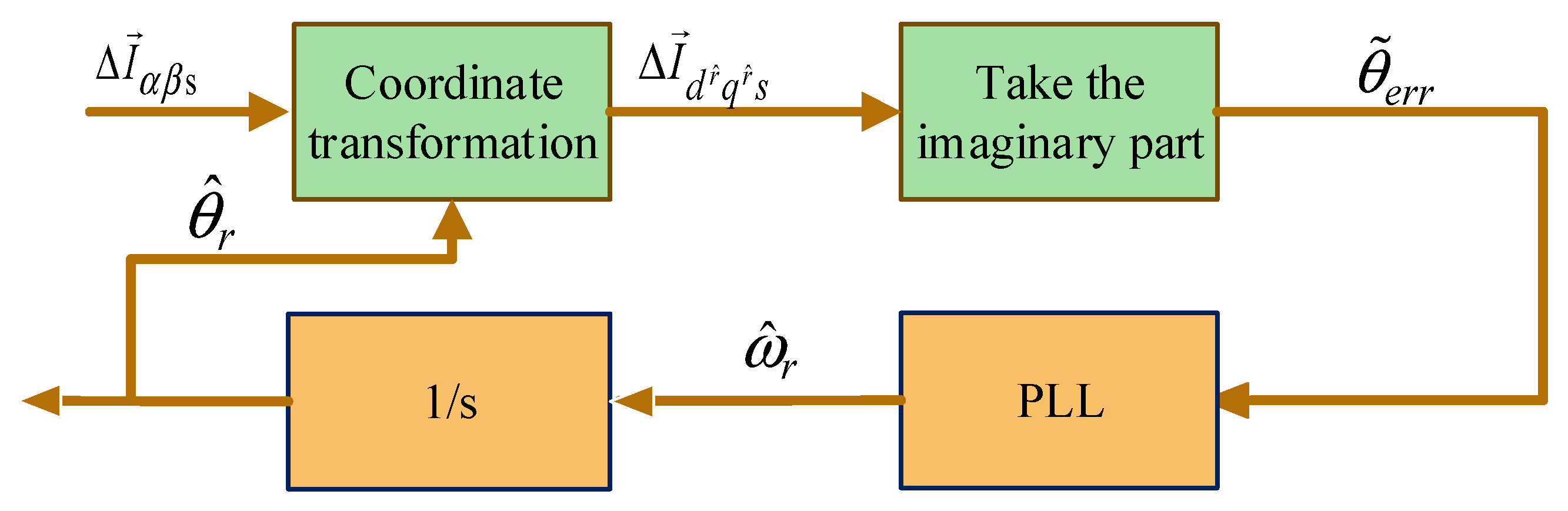
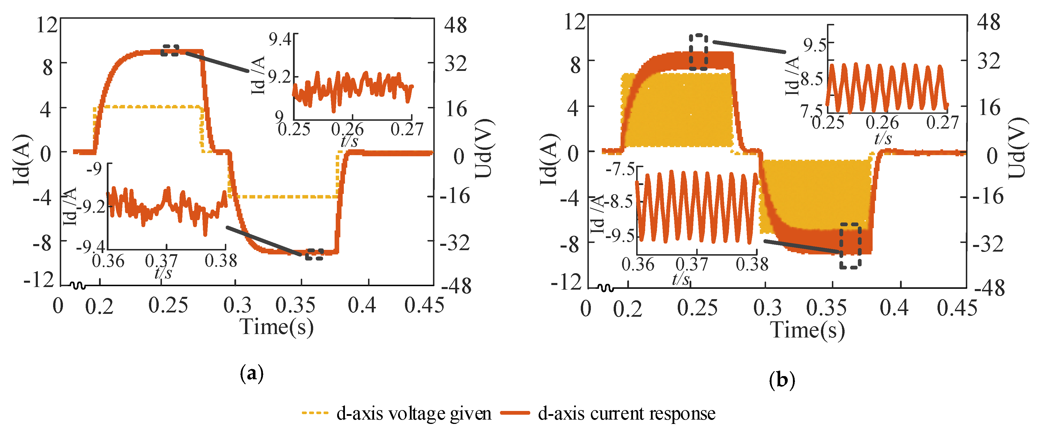
At low speeds, various position-sensorless driving methods are generally affected by the nonlinear voltage error of the inverter. The nonlinear factors in the voltage-type inverter cause the HF response current to be distorted, which results in the rotor position estimation error and affects the stability of sensorless control. If the error is not compensated, the injected voltage vector cannot be injected into the target axis accurately, resulting in the observation position offset. In (6), | L d r + L q r 2 L d r L q r | = | L d r L q r 2 L d r L q r | , when square-wave voltage is injected to the estimated d r ^ -axis, the rotor position angle error signal is obtained from the term [ Δ t ( L d r L q r ) 2 L d r L q r u i n j sin ( 2 θ ˜ e r r ) ] in the imaginary part of Δ I d r ^ q r ^ s However, due to the nonlinearity of the voltage-source inverters, the square-wave voltage cannot be injected into the target position of d r ^ -axis accurately, so a small error will be enlarged from the term [ Δ t ( L d r L q r ) 2 L d r L q r u i n j ] in the real part of Δ I d r ^ q r ^ s Therefore, when extracting the rotor position angle error signal, the term [ Δ t ( L d r L q r ) 2 L d r L q r u i n j ] will not be completely eliminated, which will seriously affect the accuracy of conventional square-wave injection for estimating the rotor position angle. In the conventional method, the observation value of rotor position can be obtained by injecting only one voltage vector in the injection period, but the voltage error affected by the nonlinearity of the voltage-source inverters is not compensated. In addition, the conventional method first calculates the error and then compensates the error, which is not only complicated to operate, but also the digital control systems, e.g., DSP and dSPACE, have a delay of switching periods. Therefore, the voltage error calculated in each switching period will only be compensated in the next switching period, which leads to inaccurate voltage error compensation. Therefore, on the basis of the above injection method, it is important to study a simple and accurate inverter voltage error compensation method to improve the accuracy of rotor position estimation and the control performance of IPMSM.
In order to realize the compensation of the voltage error caused by the nonlinear factor of the inverter, e.g., dead-time of switches and turn-on and turn-off voltage drop of switches, another voltage vector with the same amplitude and opposite direction can be injected in the next switching period of injecting the positive voltage vector on the basis of separating the FOC control period and the square-wave injection period, at which time the PI controller of current loop acts and updates every three switching periods. Figure 5 shows the inverter single-phase bridge arm structure, and the improved physical model of actual and estimated rotor reference frames is shown in Figure 6.

3.2. Improved Voltage Vector Injection Scheme

Similarly, the details of the ARM processor update in the next period after calculating the PWM duty period need to be considered. 
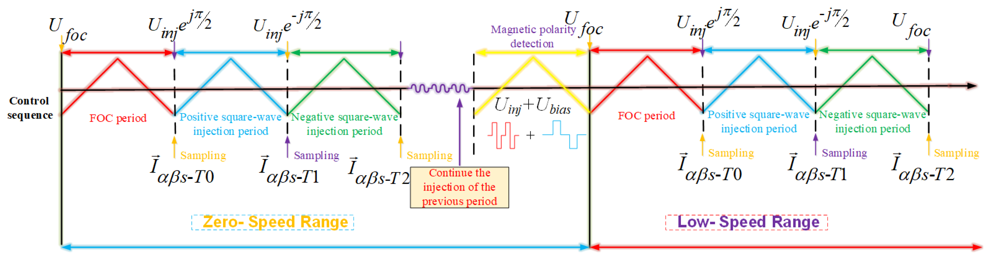
Figure 7 shows the improved control sequence of injection voltage and sampling current under position-sensorless control at zero- and low-speed. As shown in Figure 7, when the IPMSM operates at zero-speed, the initial position detection needs to be performed first, and then the magnetic polarity detection needs to be considered. When the IPMSM operates at low-speed, in the first PWM carrier period, the sensorless control system performs FOC control, without superimposing any high frequency vector. The current response generated by the FOC vector acts as the control current of three PWM periodic current loops. Then, before the beginning of the second PWM carrier period, a positive square-wave voltage is injected into the forward direction of q r ^ , and then a negative square-wave voltage of the same magnitude is injected into the reverse direction of q r ^ , before the beginning of the third PWM carrier period. Finally, the currents acquired by the second and third PWM periods are compared with the current acquired by the previous PWM period. By making a difference, two varying currents are obtained to calculate the rotor position angle.
Define the inverter voltage error as Δ U e r r I N V . Since the motor speed is very low and the switching period is very short, assuming that Δ U e r r I N V does not change during the two switching periods, the voltage error caused by the nonlinearity of the inverter can be expressed as
{ U d r ^ q r ^ s 1 = U i n j e j θ ^ u 1   U i n j e     j π / 2 Δ U e r r I N V U d r ^ q r ^ s 2 = U i n j e j θ ^ u 2   U i n j e j π / 2 Δ U e r r I N V
By substituting (12) into (7), the simplified equation is rewritten as (13) and (14)
Δ I d r ^ q r ^ s 1 = Δ t ( L d r + L q r ) 2 L d r L q r ( U i n j e     j π / 2 Δ U e r r I N V ) Δ t ( L d r L q r ) 2 L d r L q r U i n j e j ( 2 θ ˜ e r r θ ^ u 1 ) = Δ t ( L d r + L q r 2 L d r L q r U i n j e     j π / 2 L d r + L q r 2 L d r L q r Δ U e r r I N V L d r L q r 2 L d r L q r U i n j e j ( 2 θ ˜ e r r θ ^ u 1 ) )
Δ I d r ^ q r ^ s 2 = Δ t ( L d r + L q r ) 2 L d r L q r ( U i n j e     j π / 2 Δ U e r r I N V ) Δ t ( L d r L q r ) 2 L d r L q r U i n j e j ( 2 θ ˜ e r r θ ^ u 2 ) = Δ t ( L d r + L q r 2 L d r L q r U i n j e     j π / 2 L d r + L q r 2 L d r L q r Δ U e r r I N V L d r L q r 2 L d r L q r U i n j e j ( 2 θ ˜ e r r θ ^ u 2 ) )
Thus, the rotor position estimation scheme can be realized by an improved physical model of actual and estimated rotor reference frames, as shown in Figure 6. In Figure 6, the relationship between angles can be described as
{ θ ^ u 1 = π / 2 + Δ θ u 1 θ ^ u 2 = π / 2 Δ θ u 2 Δ θ u 1 Δ θ u 2
Since Δ θ u 1 is very close to 0, combining (13), (14), and (15), the obtained equation is calculated as (16).
Re ( Δ I d r ^ q r ^ s 1 Δ I d r ^ q r ^ s 2 ) = Δ t ( L d r L q r ) L d r L q r U i n j cos Δ θ u 1 sin 2 θ ˜ e r r = 2 C sin 2 θ ˜ e r r 4 C θ ˜ e r r
Similarly, if the injection voltage from the d r ^ -axis is selected, the estimated rotor position angle can be expressed as
Im ( Δ I d r ^ q r ^ s 1 Δ I d r ^ q r ^ s 2 ) = 2 C sin 2 θ ˜ e r r 4 C θ ˜ e r r
It is observed that the (16) and (17) can finally estimate the rotor position angle after considering the voltage error caused by the nonlinearity of the inverter. Thus, the rotor position-sensorless estimation scheme can be realized by an improved square-wave injection method, as shown in Figure 8.

3.3. Determining the Direction of Magnetic Polarity

In the conventional method, after the square-wave voltage is injected, the magnetic polarity is determined by injecting two square-wave pulses of opposite directions and equal durations. However, in the process of software algorithm implementation, the switching task of the algorithm state machine is additionally increased, which makes the structure of the code more complicated, and the noise of the current sampling affects the accuracy of the judgment, which may lead to the magnetic polarity judgment error.
In this paper, a fast-initial position identification method is proposed. After the positive and negative square-wave injection, the given d-axis bias voltage Ubias is added and the direction of the bias voltage is changed on the basis of the uninterrupted square-wave injection. By comparing the absolute value of the peak-to-peak value of the d-axis HF current response, the magnetic polarity identification is completed, which is relatively simple.
At the same time, the bias current is not directly given in this paper, but the bias current is generated by a given bias voltage. Figure 9 shows the characteristics curve of the d-axis magnetic circuit and the high-frequency current response diagram. The incremental inductance at X1 and X2 can be defined as
{ L 1 = ψ i | X 1 L 2 = ψ i | X 2
As shown in Figure 9, the incremental inductance L2 is larger than L1. Therefore, when the same flux is changed, the current at X1 changes greatly and the current at X2 changes little. Since the square-wave is not interrupted during the initial position identification process, the convergence speed of magnetic polarity identification is fast. In addition, it is necessary to set Ubias to 0 at an intermediate time period of a given bias voltage ±Ubias, so that the fundamental current returns to the initial state. When the d-axis DC bias voltage is the same as the magnetic polarity of the rotor (X1), the stator flux saturation is increased, the incremental inductance is decreased, and the absolute value of the d-axis HF response current peak-to-peak value is increased. When the voltage is opposite to the magnetic polarity of the rotor (X2), the saturation of the stator flux is weakened, the incremental inductance is increased, and the absolute value of the peak-to-peak value of the d-axis HF response current is decreased.
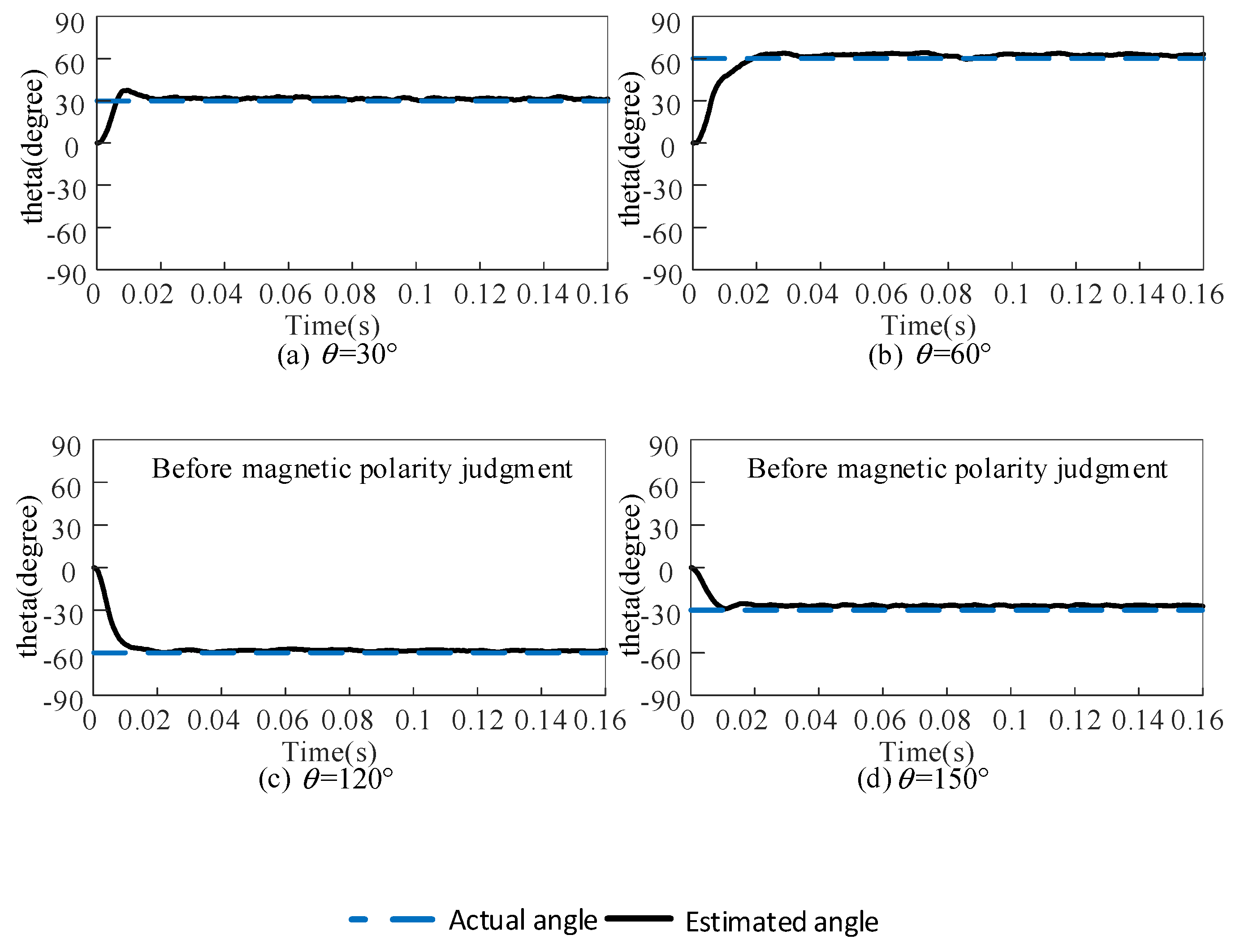
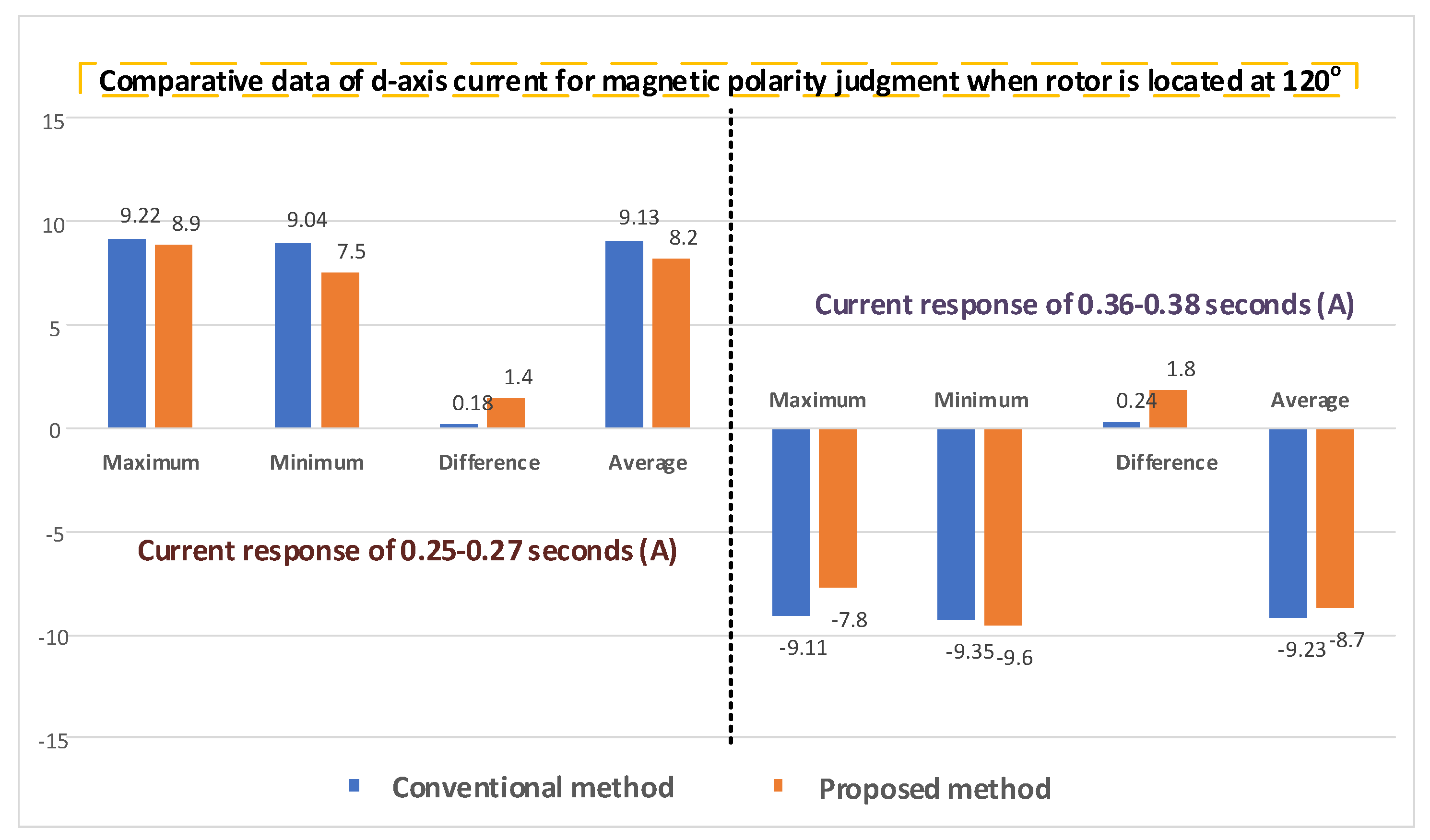
Therefore, the magnetic polarity identification of the rotor can be realized by comparing the absolute values of the peak-to-peak value of the HF current response generated by the HF voltage under the given bias of the positive and negative d-axis voltage. If the peak-to-peak value of forward HF current is greater than peak-to-peak value of the reverse HF current, the estimated position angle direction is directed to the N pole; i.e., the estimated position angle is the actual position angle of the rotor. In addition, if the peak-to-peak value of forward HF current is less than the peak-to-peak value of reverse HF current, the estimated position angle direction is directed to the S pole, which means the rotor position angle needs to be compensated for π. Figure 10 shows the flow charts of two methods for magnetic polarity identification of the rotor.

4. Simulation and Experimental Results

4.1. Simulationl Results

Because of the need to implement discrete simulation models in Matlab/Simulink, this paper uses the M function in Simulink and the data storage unit to save the discrete data for the next period of calculation. Before conducting the experiment, it is first determined by simulation that the square-wave injection is performed by injecting a HF voltage into the d-axis or a HF voltage into the q-axis. In the simulation, the bus voltage is 310 V, and the amplitude of the injected HF voltage vector is 70 V.
Figure 11 shows the current response when the q-axis is injected with positive and negative pulse voltages for position estimation. Figure 12 shows the current response when the d-axis is injected with positive and negative pulse voltages for position estimation. According to the torque equation of an IPMSM, the q-axis current has a predominant influence on the torque. As shown in Figure 11b, the HF current response with high amplitude is generated in the q-axis, which has a great influence on the torque ripple. However, as shown in Figure 12b, it can be seen that the amplitude of the HF current response in the q-axis is small, which is more conducive to the stability of the control system. Therefore, in subsequent experiments, the rotor position estimation is performed by injecting a HF voltage vector in the d-axis instead of the q-axis injection.

4.2. Experimental Platform

In order to verify the feasibility of this method in engineering and the accuracy of rotor position estimation, the proposed position-sensorless control scheme was verified on the platform with a 400W IPMSM, as shown in Figure 13. As shown in Figure 13, the experimental platform mainly includes two parts: the tested system and the load system.
The tested system can be mainly divided into three groups: (1) the upper computer for status monitoring, (2) the built-in pump motor as the controlled object, and (3) the control and drive system with the Infineon XMC4500 chip as the core. The load system can be mainly divided into three groups: (1) the upper computer for command transmission and status monitoring, (2) the industrial servo drive, and (3) the high-performance servo motor as load. In addition, the controlled motor and the load motor are connected by speed and torque sensors. The IPMSM and system parameters are shown in Table 2.

4.3. Initial Rotor Position Estimation

In the experiment, the PWM switching frequency remains unchanged at 10 kHz. The rotor position estimated by the conventional HF square-wave voltage injection method and the improved HF square-wave voltage injection method are compared, and the obtained experimental waveforms are shown in Figure 14 and Figure 15.
The experimental conditions are as follows: the conventional HF square-wave injection frequency is 10 kHz, and the rotor position is estimated every two PWM switching periods. The improved HF square-wave injection frequency is 10 kHz, and rotor position estimation is performed every three PWM switching periods. The initial position angle is artificially fixed at 30°, 60°, 120°, and 150° in advance by acquiring the angle of the encoder. Figure 16 shows the offset angles of the estimated and actual angles of the two methods. The initial position detection in Figure 14c,d and Figure 15c,d are both before the magnetic polarity judgment, and the magnetic polarity judgment are analyzed in the subsequent experiments.
By summarizing the eight initial position estimation response curves in Figure 14 and Figure 15, the relevant data in Table 3 can be sorted out. In addition, the angle error offset is the size of the offset angle generated on the basis of the actual angle, and the fluctuation range of the angle error is generated on the basis of the angle error offset.
As shown in Figure 16, the estimated angle of the conventional HF square-wave voltage injection method is offset from the actual angle, but this offset is weakened in the improved HF square-wave voltage injection method, in the conventional method, the angle error offset keep within 6.4°, which is caused by the inverter voltage error, in the improved method, the angle error offset keep within 3.2°, it can be seen that the angle error offset is greatly reduced, which is reduced by about 50%, because the improved method reduces the voltage error caused by the nonlinearity of the inverter. It can effectively compensate the voltage error and reduce the influence of the error on the accuracy of rotor position estimation.

4.4. Estimation of Rotor Position at Low Speed

4.4.1. Comparison of Rotor Position Estimation Before and After Improvement

In the HF injection sensorless control period, the FOC control period time is 100 microseconds, and the positive voltage injection period and negative voltage injection period are also 100 microseconds. Figure 17 shows the comparison of rotor position estimation before and after improvement. As shown in Figure 17a, in the conventional method, the estimation error results in an offset error of around 5° and an estimated ripple error of ±7°. However, in the improved method of Figure 17b, the offset error is close to 0° and the estimated ripple error is kept within ±5°. The analysis diagram of steady-state estimation error of two methods under different low speed conditions is shown in Figure 18.

4.4.2. Rotor Position Observation Experiment Under Forward and Reverse

Figure 19a shows the rotor angle and estimation error waveform of conventional HF square-wave voltage injection method switching back and forth from 5 r/min to −5 r/min. It can be seen that the estimated ripple error can be stabilized within ±10° when the rotation speed is 5 r/min, as shown in Figure 19a. The rotor angle and estimation error waveform of conventional HF square-wave voltage injection method switches back and forth from 20 r/min to −20 r/min, as shown in Figure 19b. It can be seen that the estimated ripple error can be stabilized within ±10° when the rotation speed is 20 r/min, as shown in Figure 19b.
The rotor angle and estimated error waveform switching back and forth from 5 r/min to −5 r/min and the rotor angle and estimated error waveform switching back and forth from 20 r/min to −20 r/min are shown in Figure 20a,b, respectively. As shown in Figure 20a, it can be seen that the estimated ripple error can be stabilized within ±6° when the rotation speed is 5 r/min. It can be seen that the estimated ripple error can be stabilized within ±8° when the rotation speed is 20 r/min, as shown in Figure 20b.

4.5. Judging Compensation of Magnetic Polarity Direction

In this section, the effects of the two magnetic polarity discrimination methods are compared at 30° and 120°, respectively. The magnetic polarity discrimination experiments of the two methods at 30° are shown in Figure 21a,b, respectively. As shown in Figure 21a, the conventional method uses a 20 V DC bias voltage to identify the magnetic polarity. The proposed method uses a 20 V DC bias voltage to superimpose a 16 V HF square-wave voltage signal, as shown in Figure 21b.
Similarly, the magnetic polarity discrimination experiments of the two methods at 120° are shown in Figure 22a,b, respectively. The experimental data are compared in detail, as shown in Figure 23 and Figure 24. We can divide the process into two stages. When t is between 0 and 0.18 s, the first stage period is the from standstill to startup, that is no procedure and no equipment to be performed at standstill, and the rotor is fixed initially in the startup period. Then, during the second stage, when t is between 0.18 and 0.38 s, the magnetic polarity judgment is performed in order to ensure the accuracy of rotor position estimation. The magnetic polarity identification method proposed in this paper is a combination of HF square-wave voltage injection method and DC bias voltage. In the process of magnetic polarity identification, the HF square-wave voltage injection method has also been updating its angle.
Therefore, the method of magnetic polarity identification proposed in this paper is not only suitable for the case where the motor is stationary, but also suitable for the free running condition of the motor. As can be seen from the Figure 21 and Figure 22, the effect of only injecting DC bias voltage on the initial position observation is not very obvious either from the difference of the extreme value of the d-axis current response or from the average value of the steady-state current of the d-axis. If the burr of the current is large, it is easy to affect the judgment result. In 50 repetitive experiments, the probability of method (a) judging errors was about 10%. For method (b), the discrimination is more obvious from the difference of high frequency response of current. In 50 repetitive experiments, the probability of misjudgment was 0, which directly proved that the improved direction judgment of magnetic polarity method proposed in this paper is effective.

5. Conclusions

In this paper, a HF square-wave voltage injection scheme-based position sensorless control of IPMSM in the low-speed range and a new method of magnetic polarity detection in zero-speed range are proposed. The strategy realizes the switch between zero-speed algorithm and low-speed algorithm for sensorless control of IPMSM. Since the proposed method is an improvement on the conventional square-wave injection method, the method is applicable to AC motors with salient pole effect that can be applied in the conventional method. Furthermore, the voltage error caused by the nonlinearity of the inverter are compensated to improve the accuracy of rotor position estimation. In addition, based on the principle analysis of d-axis magnetic circuit characteristics, a method for determining the direction of magnetic polarity of d-axis two-opposite DC voltage offset by uninterruptible square-wave injection is proposed, which is fast in the convergence rate of magnetic polarity detection Compared with the conventional method, the new method is more distinct and the success rate is higher. Finally, comprehensive simulation and experimental results verify that the improved HF square-wave voltage injection method and the detection of magnetic polarity method perform faster and more accurately compared with the conventional method.

Author Contributions

Conceptualization, S.W. and J.Z.; methodology, S.W. and J.Z.; software, K.Y.; validation, S.W., J.Z. and K.Y.; formal analysis, W.S.; data curation, K.Y.; writing—original draft preparation, S.W. and J.Z.; writing—review and editing, S.W. and J.Z. All authors gave advice for the manuscript.

Funding

This work was supported in part by the National Key Research and Development Program of China under Grant 2018YFB0104801.

Conflicts of Interest

The authors declare no conflict of interest.

References

  1. Onambele, C.; Elsied, M.; Mpanda Mabwe, A.; El Hajjaji, A. Multi-Phase Modular Drive System: A Case Study in Electrical Aircraft Applications. Energies 2018, 11, 5. [Google Scholar] [CrossRef] [Green Version]
  2. Zhang, C.; Guo, Q.; Li, L. System Efficiency Improvement for Electric Vehicles Adopting a Permanent Magnet Synchronous Motor Direct Drive System. Energies 2017, 10, 2030. [Google Scholar] [CrossRef] [Green Version]
  3. Hua, W.; Zhou, K.L. Investigation of a Co-Axial Dual-Mechanical Ports Flux-Switching Permanent Magnet Machine for Hybrid Electric Vehicles. Energies 2015, 8, 14361–14379. [Google Scholar] [CrossRef]
  4. Wang, S.; Yang, K.; Chen, K. An Improved Position-Sensorless Control Method at Low Speed for PMSM Based on High-Frequency Signal Injection into a Rotating Reference Frame. IEEE Access 2019, 7, 86510–86521. [Google Scholar] [CrossRef]
  5. Zhang, X.; Hou, B.; Mei, Y. Deadbeat Predictive Current Control of Permanent-Magnet Synchronous Motors with Stator Current and Disturbance Observer. IEEE Trans. Power Electron. 2017, 32, 3818–3834. [Google Scholar] [CrossRef]
  6. Park, Y.; Sul, S. Sensorless Control Method for PMSM Based on Frequency-Adaptive Disturbance Observer. IEEE J. Emerg. Sel. Top. Power Electron. 2014, 2, 143–151. [Google Scholar] [CrossRef]
  7. Zhang, G.; Wang, G.; Xu, D.; Zhao, N. ADALINE-Network-Based PLL for Position Sensorless Interior Permanent Magnet Synchronous Motor Drives. IEEE Trans. Power Electron. 2016, 31, 1450–1460. [Google Scholar] [CrossRef]
  8. Nguyen, H.Q.; Yang, S. Rotor Position Sensorless Control of Wound-Field Flux-Switching Machine Based on High Frequency Square-Wave Voltage Injection. IEEE Access 2018, 6, 48776–48784. [Google Scholar] [CrossRef]
  9. Wang, T.; Zhang, H.; Gao, Q.; Xu, Z.; Li, J.; Gerada, C. Enhanced Self-Sensing Capability of Permanent-Magnet Synchronous Machines: A Novel Saliency Modulation Rotor End Approach. IEEE Trans. Ind. Electron. 2017, 64, 3548–3556. [Google Scholar] [CrossRef]
  10. Wang, G.; Yang, L.; Yuan, B.; Wang, B.; Zhang, G.; Xu, D. Pseudo-Random High-Frequency Square-Wave Voltage Injection Based Sensorless Control of IPMSM Drives for Audible Noise Reduction. IEEE Trans. Ind. Electron. 2016, 63, 7423–7433. [Google Scholar] [CrossRef]
  11. Wang, G.; Yang, L.; Zhang, G.; Zhang, X.; Xu, D. Comparative Investigation of Pseudorandom High-Frequency Signal Injection Schemes for Sensorless IPMSM Drives. IEEE Trans. Power Electron. 2017, 32, 2123–2132. [Google Scholar] [CrossRef]
  12. Wang, G.; Xiao, D.; Zhao, N.; Zhang, X.; Wang, W.; Xu, D. Low-Frequency Pulse Voltage Injection Scheme-Based Sensorless Control of IPMSM Drives for Audible Noise Reduction. IEEE Trans. Ind. Electron. 2017, 64, 8415–8426. [Google Scholar] [CrossRef]
  13. Almarhoon, A.H.; Zhu, Z.Q.; Xu, P. Improved Rotor Position Estimation Accuracy by Rotating Carrier Signal Injection Utilizing Zero-Sequence Carrier Voltage for Dual Three-Phase PMSM. IEEE Trans. Ind. Electron. 2017, 64, 4454–4462. [Google Scholar] [CrossRef]
  14. Seilmeier, M.; Piepenbreier, B. Sensorless Control of PMSM for the Whole Speed Range Using Two-Degree-of-Freedom Current Control and HF Test Current Injection for Low-Speed Range. IEEE Trans. Power Electron. 2015, 30, 4394–4403. [Google Scholar] [CrossRef]
  15. Zhang, G.; Wang, G.; Yuan, B.; Liu, R.; Xu, D. Active Disturbance Rejection Control Strategy for Signal Injection-Based Sensorless IPMSM Drives. IEEE Trans. Transp. Electrif. 2018, 4, 330–339. [Google Scholar] [CrossRef]
  16. Luo, X.; Tang, Q.; Shen, A.; Zhang, Q. PMSM Sensorless Control by Injecting HF Pulsating Carrier Signal into Estimated Fixed-Frequency Rotating Reference Frame. IEEE Trans. Ind. Electron. 2016, 63, 2294–2303. [Google Scholar] [CrossRef]
  17. Yoon, Y.; Sul, S.; Morimoto, S.; Ide, K. High-Bandwidth Sensorless Algorithm for AC Machines Based on Square-Wave-Type Voltage Injection. IEEE Trans. Ind. Appl. 2011, 47, 1361–1370. [Google Scholar] [CrossRef]
  18. Ni, R.; Xu, D.; Blaabjerg, F.; Lu, K.; Wang, G.; Zhang, G. Square-Wave Voltage Injection Algorithm for PMSM Position Sensorless Control with High Robustness to Voltage Errors. IEEE Trans. Power Electron. 2017, 32, 5425–5437. [Google Scholar] [CrossRef]
  19. Kim, S.; Ha, J.; Sul, S. PWM Switching Frequency Signal Injection Sensorless Method in IPMSM. IEEE Trans. Ind. Appl. 2012, 48, 1576–1587. [Google Scholar] [CrossRef]
  20. Park, N.; Kim, S. Simple sensorless algorithm for interior permanent magnet synchronous motors based on high-frequency voltage injection method. IET Electr. Power Appl. 2014, 8, 68–75. [Google Scholar] [CrossRef]
  21. Chen, L.; Götting, G.; Dietrich, S.; Hahn, I. Self-Sensing Control of Permanent-Magnet Synchronous Machines with Multiple Saliencies Using Pulse-Voltage-Injection. IEEE Trans. Ind. Appl. 2016, 52, 3480–3491. [Google Scholar] [CrossRef]
  22. Hu, J.; Liu, J.; Xu, L. Eddy Current Effects on Rotor Position Estimation and Magnetic Pole Identification of PMSM at Zero and Low Speeds. IEEE Trans. Power Electron. 2008, 23, 2565–2575. [Google Scholar] [CrossRef]
  23. Jin, X.; Ni, R.; Chen, W.; Blaabjerg, F.; Xu, D. High-Frequency Voltage-Injection Methods and Observer Design for Initial Position Detection of Permanent Magnet Synchronous Machines. IEEE Trans. Power Electron. 2018, 33, 7971–7979. [Google Scholar] [CrossRef]
  24. Xie, G.; Lu, K.; Dwivedi, S.K.; Rosholm, J.R.; Blaabjerg, F. Minimum-Voltage Vector Injection Method for Sensorless Control of PMSM for Low-Speed Operations. IEEE Trans. Power Electron. 2016, 31, 1785–1794. [Google Scholar] [CrossRef]
  25. Liu, Y.; Zhou, B.; Li, S.; Feng, Y. Initial Rotor Position Detection of Surface Mounted Permanent Magnet Synchronous Motor. Proc. CSEE 2011, 31, 48–54. [Google Scholar]
  26. Yan-Jun, Y.U.; Gao, H.W.; Chai, F.; Cheng, S.K. Rotor magnetic polarity detection method for PMSM. Elect. Mach. Control. 2011, 15, 86–90. [Google Scholar]
  27. Jeong, Y.S.; Lorenz, R.D.; Jahns, T.M.; Sul, S.K. Initial rotor position estimation of an interior permanent-magnet synchronous machine using carrier-frequency injection methods. IEEE Trans. Ind. Appl. 2005, 41, 38–45. [Google Scholar] [CrossRef] [Green Version]
  28. Raute, R.; Caruana, C.; Staines, C.S.; Cilia, J.; Sumner, M.; Asher, G. Operation of a sensorless PMSM drive without additional test signal injection. In Proceedings of the 2008 4th IET Conference on Power Electronics, Machines and Drives, York, UK, 2–4 April 2008; pp. 616–620. [Google Scholar]
Figure 1. Physical model of the actual and estimated rotor reference frames.
Energies 12 04776 g001
Figure 2. Control system scheme for obtaining position information with the conventional square-wave injection method.
Energies 12 04776 g002
Figure 3. Signal processing diagram of the conventional square-wave voltage injection method for IPMSM.
Energies 12 04776 g003
Figure 4. Conventional control sequence of injection voltage and sampling current at zero- and low-speed.
Energies 12 04776 g004
Figure 5. Inverter single-phase bridge arm structure.
Energies 12 04776 g005
Figure 6. The improved physical model of actual and estimated rotor reference frames.
Energies 12 04776 g006
Figure 7. The improved control sequence of injection voltage and sampling current at zero- and low-speed.
Energies 12 04776 g007
Figure 8. Control system scheme for obtaining position information with the improved square-wave injection method.
Energies 12 04776 g008
Figure 9. The characteristics curve of the d-axis magnetic circuit and the high-frequency current response diagram.
Energies 12 04776 g009
Figure 10. The flow charts of two methods for magnetic polarity identification of the rotor.
Energies 12 04776 g010
Figure 11. Current response when the q-axis is injected with positive and negative pulse voltages for position estimation.
Energies 12 04776 g011
Figure 12. Current response when the d-axis is injected with positive and negative pulse voltages for position estimation.
Energies 12 04776 g012
Figure 13. The experimental platform.
Energies 12 04776 g013
Figure 14. Initial position estimation response curve under conventional HF square-wave voltage injection.
Energies 12 04776 g014
Figure 15. Initial position estimation response curve under improved HF square-wave voltage injection.
Energies 12 04776 g015
Figure 16. The angle error offset of the two methods.
Energies 12 04776 g016
Figure 17. Comparison of rotor position estimation effects between two methods (a) Conventional method; (b) Improved method.
Energies 12 04776 g017
Figure 18. Steady-state estimation error of two injection methods at different speeds.
Energies 12 04776 g018
Figure 19. The rotor angle and estimation error waveform of conventional HF square-wave voltage injection method at low-speed operation (a) at 5 r/min. (b) at 20 r/min.
Energies 12 04776 g019
Figure 20. The rotor angle and estimation error waveform of improved HF square-wave voltage injection method at low-speed operation (a) at 5 r/min. (b) at 20 r/min.
Energies 12 04776 g020
Figure 21. The d-axis current characteristic of the rotor at 30° for magnetic polarity judgment (a) conventional method. (b) proposed method.
Energies 12 04776 g021
Figure 22. The d-axis current characteristic of the rotor at 120° for magnetic polarity judgment (a) conventional method. (b) proposed method.
Energies 12 04776 g022
Figure 23. Comparative data of d-axis current characteristics for magnetic polarity judgment when rotor is located at 30°.
Energies 12 04776 g023
Figure 24. Comparative data of d-axis current characteristics for magnetic polarity judgment when rotor is located at 120°.
Energies 12 04776 g024
Table 1. List of the research contents covered by the articles.
LiteratureRemove
LPF
Remove
BPF/HPF
Reduce Audible NoiseNonlinearity of the InverterMagnetic Polarity Judgment
Ref. [4]××××
Ref. [8]×××
Ref. [10]××××
Ref. [11]××××
Ref. [12]××
Ref. [13]×××
Ref. [15]×××
Ref. [16]×××
Ref. [18]××
Ref. [23]××
Ref. [24]××
This paper×
Table 2. IPMSM and system parameters for experiment.
ParameterQuantityUnit
Pole pairs2poles
Resistance1.6[Ω]
d-axis inductance15[mH]
q-axis inductance18.8[mH]
Rated speed3000[rpm]
Rated power400[W]
Rated voltage220[V]
Rated current2.28[A]
Rated torque1.27[N·m]
PWM switching frequency10[kHz]
Injection voltage magnitude70[V]
Table 3. Comparison of initial position estimation parameters for two injection methods.
Injection Method30°60°120°150°
Time (s)error (°)Time (s)error (°)Time (s)error (°)Time (s)error (°)
Conventional method0.018±3.3 + 6.20.02±3.4 + 6.40.016±3.2 + 5.90.012±3.6 + 6.2
Improved method0.022±3.4 + 3.20.032±3.2 + 2.40.023±2.9 + 1.90.017±3.6 + 2.2

