1. Introduction
According to the literature engine manufacturer’s service information and the authors’ own experience [
1,
2,
3,
4] the number of incidents involving the fuel injection pump (FIP) and its precision pair barrel-plunger (B-P) installed in marine 2-strokes, crosshead, slow-speed diesel engines is steadily increasing. This has a large impact on the performance of ships and engines particularly operating at low loads due to operational and economic reasons. Although due to tribological processes, the internal wear in the B-P pair is unavoidable, the degree and progress of wear are largely dependent on operational and maintenance conditions, and on use of fuel oil quality and the possibility of its purification and filtration in ship installations. In addition, due to the steadily deteriorating quality of fuel oils and catalytic additives (Cat-fines) used in the refining processes of crude oil to reduce sulfur content to comply with environmental requirements [
5,
6], the problem of the deterioration of working conditions in a FIP become significant.
The surface quality of precision assemblies in the injection pump has a large impact on the proper operation of the engine. Both the plunger and the barrel of the pumping section are adjusted so that the gap between the side surface of the plunger and the inner surface of the barrel is approximately 2–5 μm. This clearance provides sufficient lubrication of the side surfaces of the plunger and barrel, while still providing enough sealing to maintain the high-pressure of fuel. The penetration of slurry deposits between the surface of the plunger and the barrel can cause the sticking of the pumping elements, as was the case with the reported findings. The sticking of pumping elements was repeatedly observed after the operation with high-percentage biodiesel blends and the shutdown of the engines for a period of two months or more [
7].
Currently, FIP inspections are carried out in accordance with the TBO (time between overhauling), which is based on working hours. As per the engine’s manuals, periods and schedules for FIP inspection, cleaning, maintenance, and overhauling, including limits and conditions for the replacement of FIP elements, that are usually between 15,000 to 20,000 running hours (RH), are called major overhaul and carried out in dry docks by a specialized service. The inspections on board mostly come down to visual assessment, which is not sufficient and practically performed in case of FIP failure, causing the engine to not be able to start and then requiring the replacement of the B-P pair and/or an overhaul of the pump. Measurements of pressure changes in the combustion chamber are widely implemented but difficult in use to FIP diagnosis, while measurements of pressure changes during the injection process are not met in operation because they require a mounting sensor in each fuel pipe. In addition, vessels, such as tankers, are limited with time for maintenance, and even once they are in port, any immobilization of the main engine is not allowed. Considering the above, there is a necessity to elaborate methods that will assist a ship’s crew to avoid operational problems, to indicate the sequence and priorities in choosing FIP for intermediate overhauling, and, in addition, to search for alternative methods of FIP diagnosis that can be used as a proactive tool in condition monitoring.
2. Analysis of Operational Problems Occurring in Fuel Injection Pump
Material fuel injection pumps (FIP) are one of the main components of a diesel engine and have a significant impact on its performance and reliability. The design and construction determine the amount of fuel injected and the injection time. There are two types of fuel injection pumps in marine construction of 2-strokes, crosshead, slow-speed diesel engines utilized as main propulsion engines (M/E) with a difference in the method of controlling fuel quantity. The first method uses suction and spill valves operated by a push rod (Wartsila RTA engines), and the second method, as the subject of this article, uses a precision pair: barrel and helical plunger, as shown in
Figure 1.
One of the important key parameters of marine diesel engines is finding a useful tool to improve energy efficiency. There are two steps to improve the energy efficiency on ships: measurement and evaluation of the performance of the main fuel consumers. Performance evaluation is the method that evaluates how much the performance change is owing to engine component degradation, which causes a reduction in the performance due to wear, fouling, mechanical problems, etc. [
8,
9].
According to the literature [
10,
11,
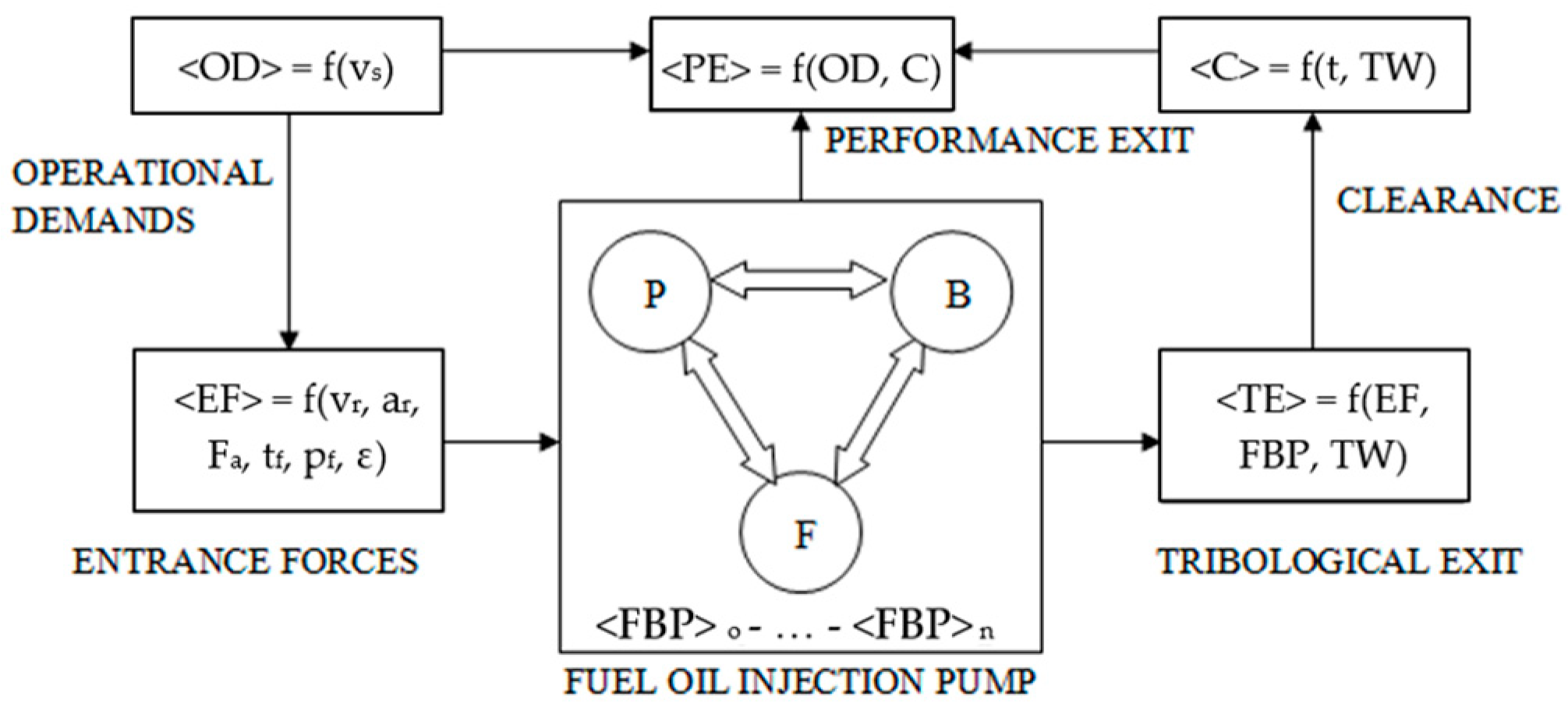
12], the hydraulic precision pair is one in which two elements of barrel/cylinder (B) and plunger/piston (P) are separated by working fluid, for example fuel oil (F) forming the third structural element of machine and tribological node (FBP), as shown in
Figure 2.
Fuel oil in the FIP simultaneously satisfies the functions of lubricating, cooling, and sealing, working in an open system with recirculation allowing a continuous flow of fresh fuel corresponding to feed rate. Thus, it is an element of the FBP node, which is the most susceptible to external/entrance forces (EF), and its quality and content of impurities significantly affects parameters of performance exit/output (PE) described by the pump performance/efficiency (CP) and reflects on parameters of tribological exit/output (TE) characterizing tribological processes (TP). B-P elements during operation perform a reciprocating-rotational motion, and the tightness of assembly is not ensured by piston/sealing rings but by the application of minimum radial clearances, which are from 5 μm to 25 μm (50-micron limit) depending on the cylinder liner bore/diameter and power achieved by one cylinder [
13]. Thus, the clearance measure is a parameter binding the responses of performance output (PE) and tribological exit (TE), whereas the input measures—external forces (EF) and performance output (PE)—are dependent on operational demands (OD) related to the ship’s speed.
Typical operational problems occurring in FIP elements are summarized in
Table 1.
It shows the possible causes leading to the FIP elements wear or faults in operation and the possible remedies. The first two are the most important from them (excluding case 6, as it is very rare), as they are the main cause of the increased number of incidents involving the FIP and its B-P occurring during starting the engine and leading to situations in which the engine cannot be started without overhauling the faulty pump. Furthermore, as it was reported [
13], and according to co-authors sea-going experience, those incidents, in some cases, were involving not only the one FIP but also a few of them or even all units simultaneously, which required a minimum of three days of vessel-for-hire to restore their condition and to have the M/E operational, therefore causing significant impact on the ship owner’s business. Seizure of the B-P pair of FIP occurs if the clearance between the plunger and the barrel is reduced or if there is a lack of lubrication. Thus, the most common cause of the jamming and seizure of a B-P pair in FIP, and as a consequence, troubles with re-starting the engines, are the excessive changes in fuel temperature (changes in fuel viscosity, and hence drop of oil film density/thickness) during the changing over of the different fuel grades while having to go from residual to distillate fuels, and vice versa.
In Mitsubishi UEC engines, lubricating oil used in an engine’s lube oil system is fed continuously through an orifice and drilled-sleeve in the FIP barrel to the fuel rack (
Figure 1a, yellow field) in order to lubricate and wash down fuel deposits. At the same time, it lubricates and cleans the lower part of the FIP and washes the spring chamber (
Figure 1a, green part). If the oil flow is in some way limited (accumulation of sludge, clogged drain line) or there is a fuel leak due to wear of the B-P pair, the lubrication and cleaning of these FIP elements may not be sufficient and may lead to seizure between the fuel rack’s control sleeve and barrel and B-P pair jamming, or so-called sticking (adhesive vaccination), disenabling the engine to start, as shown in
Figure 3.
In MAN B&W MC engines, sticking of FIP elements were observed as the result of a decrease in fuel viscosity during engine stoppage (especially in cold climate) and formation of deposits in FIP parts around the suction valve and upper part of the barrel (
Figure 1b, red part;
Figure 4a). This leads to clogging of the drain/circulating line and causes the VIT rack to stick, not allowing the barrel to move up/down, consequently disturbing fuel injection timing. It is also the reason for the deposition and presence of hardened remains of residual fuel in the lower part of the plunger (
Figure 1b, green part;
Figure 4b), disenabling the engine to start.
3. Methods of Condition Monitoring of the Fuel Injection Pump
The safety and reliability of a ship’s work rely strongly on the performance of such an engine; therefore, early detection of any type of failure that affects the engine is of crucial importance. Automatic diagnostic systems are of special importance because they can operate continuously in real time, thereby providing efficient monitoring of the engine’s performance. The authors of [
14] introduced a fully automatic machine learning-based system for engine fault detection. For this purpose, they monitored various signals that are emitted by the engine and used them as an input for a pattern classification algorithm [
15].
Proactive countermeasures that can be applied by ship’s staff to avoid operational problems with the FIP of marine 2-strokes, crosshead, slow-speed diesel engines are as follows:
Maintaining sufficient flow of washing oil, keeping the drain line and drain box clean;
Following engine manufacture’s maintenance/inspection guidelines [
16];
Carrying out proper onboard fuel treatment described in author’s publications [
17];
Following recommendations for operation included in fuel oil analysis reports;
Avoiding cold air flow from engine room fans blowing directly on FIP body and piping;
Following onboard fuel oil changeover procedures with consideration of reduced engine load (below 30% MCR), ensuring that viscosity does not drop below 2 mm2/s (cSt) and that the rate of temperature change of the fuel inlet to the fuel pumps does not exceed 2 °C/minute.
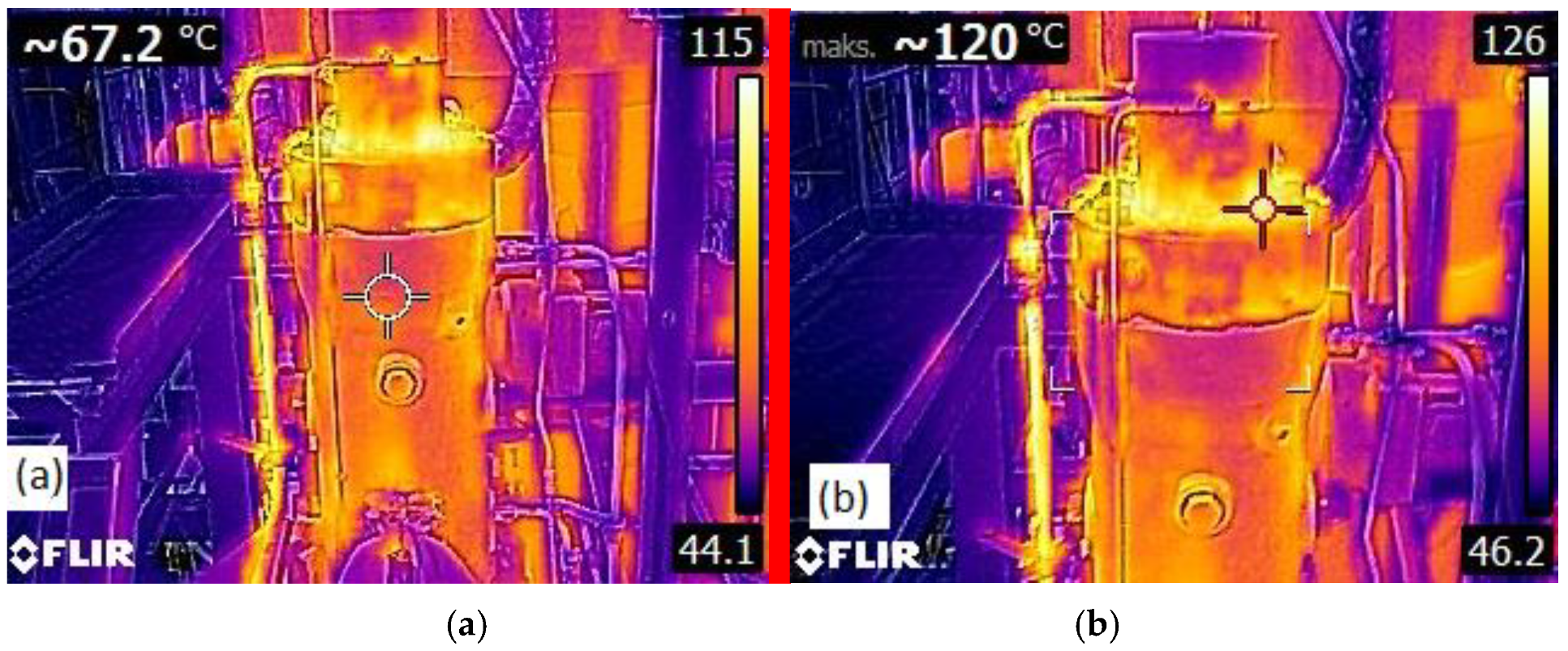
However, the mentioned precaution still does not ensure that problems during the starting of the engine will not appear due to a faulty FIP. Another difficulty is indicating the sequence and priorities in choosing FIP for overhauling as per the maintenance schedule (all units become due at the same time), bearing in mind limitations caused by time and permission for M/E immobilization. Therefore, the alternative methods are searched to assist the ship’s staff in FIP condition monitoring. One solution is the thermal checking of the FIP elements by thermographic cameras, allowing visualization of the FIP in Multi-Spectral Dynamic Imaging (MSX) with a temp. information display, emissivity (level of radiation), thermal contrast, and heat distribution, as shown in
Figure 5. This can help detect abnormalities in case of an accumulation of fuel deposits in the upper part of the B-P or obstructed fuel recirculation through drain pipes in case of a defected pump, allowing preventive maintenance to be carried out before the engine is to be used.
Other instruments that can be used for the diagnosis of the FIP are vibration meters, which are also applied more and more onboard the vessels to monitor the condition of various machinery, such as centrifugal machines and their electrical motors based on rotary movement. Good diagnostic results can be obtained with their application in proactive maintenance after setting the boundary values and limits for monitored machines. However, condition monitoring of displacement machines with reciprocating–rotational motion (stroke movement) is more difficult in analysis, and so far, it is based on the measurement of courses of pressure changes in a working area, for example, in the crank angle function of diesel engines.
Acoustic emission sensing techniques have been applied in recent years to dynamic machinery with varying degrees of success in diagnosing various component faults and distinguishing between operating conditions. The authors of [
18] have explored the basic properties of acoustic emission signals measured on a small single-cylinder diesel engine in a laboratory setting. As reported in other works in the open literature, the measured acoustic emission on the engine is mostly a continuous mode, and individual burst events are generally not readily identifiable. Crank-resolved spectral representation of the AE is also given, but a rigorous investigation of the AE spectral qualities has been left for future study. Furthermore, during the course of testing, the fuel injector developed a fault, acoustic emission signals were captured, and several signal attributes were successful in distinguishing this altered condition. The sampling and use of instantaneous RMS acoustic emission signals demonstrated promise for a non-intrusive and economical change detection of engine injection, combustion, and valve events [
18].
Therefore, based on previous experience, the application of elastic waves of acoustic emission signals in condition monitoring of the FIP was proposed. Acoustic emission is an elastic wave released in a material. Such waves are formed as a result of intermolecular bond energy release, caused by such factors as strain, cracking, phase transitions, and wear [
19]. As mentioned, the main problem encountered in vibration measurements is a low signal-to-noise ratio. High wave frequencies generated in the material structure (in the form of acoustic emission) substantially improve this signal measure. The course of changes in the AE signal in the time domain measured for the FIP is shown in
Figure 6.
4. Sensor Selection and Installation
The measurement used the FUJICERA 1045S acoustic emission sensor, and the frequency response is shown in
Figure 7.
The sensor was placed on the injection pump head at the height of the upper dead position of the piston (
Figure 8).
5. Analysis of Results and Discussion
The measured AE signals of the FIP were analyzed among others by wavelet analysis. The authors used the Gabor wavelet based on the Gaussian function [
18,
19]. The mother wavelet (1) and its Fourier transform (2) are given as:
where ω
p is the center frequency, and
is a constant taken as
.
From the Fourier transform, we find the half-value frequency width of the Gabor wavelet to be
and the half-value time width to be
. The specific value of
was chosen to nearly satisfy the so-called admissibility condition, i.e., the wavelet functions must satisfy the orthonormality condition [
19].
The results are presented in
Figure 9 for the case of a new precision pair: Barrel-Plunger (B-P), and
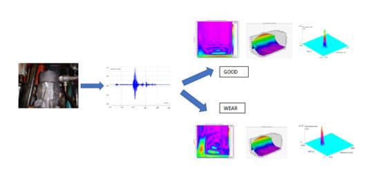
Figure 10 for the case of a B-P with enlarged clearance after 11,000 RH, caused by the use of poor quality fuel with high cat fines content. The important differences from a diagnostic point of can be seen in the time–frequency distributions in the analysis presented below. These differences are related to ongoing friction processes and changes in the P-B radial clearance.
In the case of a new injection pump, the analysis of the generation of elastic wave signals of the acoustic emission is similar to a properly working tribological node, i.e., the highest energy occurs in the lower frequency range—of the order of 50 kHz (
Figure 9). For increased clearance of the precision pair (Barrel-Plunger) of the pump, additional high-pressure cavitation processes were created and generated an increase in energy at much higher frequencies—on the order of 200–350 kHz (
Figure 10).
In analyzing the frequency content of the signal x(t), one might like to compute the ordinary Fourier transform
; however, for many signals of interest, the Fourier transform does not formally exist. Because of this complication, one can work with a truncated Fourier transform as well, where the signal is integrated only over a finite interval [0, T] (3):
This is the amplitude spectral density. Then, the power spectral density can be defined as (4):
where
E denotes the expected value.
Therefore, the other analysis method used by authors, confirming the evaluation of the FIP condition, is power-spectral-density (PSD) analysis, as shown in
Figure 11 for the same two cases.
The unit of PSD is energy per frequency (width), and it obtains energy within a specific frequency range by integrating PSD within that frequency range.
The power spectral density describes how the power of a signal is distributed over frequency, as the Fourier transform shows the spectral content of a given signal, i.e., the amplitude and phase of harmonics in the measured signal. The PSD analysis helps to isolate the most important harmonic components and to determine the magnitude of amplitudes of those components. The analysis determines the amplitudes of subsequent harmonics (the amplitude spectrum) and/or phase shifts (phase spectrum). There can be noticed differences in PSD amplitudes, clearly indicating the wear in the FIP B-P precision pair. There is also a disturbance observed in the so-called characteristic frequencies generated by the FIP.
6. Conclusions
An effective onboard management system can minimize and significantly reduce the risk of engine break-down caused by the failure of FIP elements due to jammed/sticking fuel/VIT racks and/or a seized B-P precision pair if it is implemented and followed at all times. Proactive countermeasures mentioned in this article can help to avoid operational problems with the FIP and to minimize delays in commercial operations and additional costs due to the unavailability of M/E, but cannot solve them completely, especially due to the limitation of establishing the prioritization of FIP overhauling as per the maintenance schedule [
20,
21,
22,
23].
The presented researches and analysis allow us to state that the AE signal can be very useful in finding diagnostic symptoms determining the FIP condition. When the condition of the FIP deteriorates due to wear, the radial clearance of the B-P pair increases, the friction between them decreases, and there are characteristic frequencies generated mainly connected with specific friction processes. An additional analysis with the use of elastic waves of acoustic emission confirmed the author’s assumption that the presence of a characteristic frequency value in reference to signals from a new pump will enable verification and identification of the limit value of the B-P precision pair condition. The authors have also found that the AE signal power spectral density (PSD) analysis is a good method for confirming the evaluation of the technical condition of an injection pump. The visible differences in power spectral density amplitudes clearly indicate the substantial wear of a pump’s precision pair. We can also observe a disturbance in the so-called characteristic frequencies generated by the system. Further discussions on issues concerning FIP diagnosis and the proposition of a new method with the use of AE signals to diagnosis the wear limit states will be presented in future publications.


