Article

Improved SVPWM Fault-Tolerant Control Strategy for Five-Phase Permanent-Magnet Motor

1
School of Electrical and Information Engineering, Jiangsu University, Zhenjiang 212013, China
2
Jiangsu Key Laboratory of Drive and Intelligent Control for Electric Vehicle, Zhenjiang 212013, China
*
Author to whom correspondence should be addressed.
Energies 2019, 12(24), 4626; https://doi.org/10.3390/en12244626
Submission received: 19 November 2019 / Revised: 1 December 2019 / Accepted: 4 December 2019 / Published: 5 December 2019
(This article belongs to the Special Issue Electric Machines and Drive Systems for Emerging Applications)

Abstract

:
Multiphase permanent-magnet motors have received a lot of attention in the past few years owing to the merits of high power density, high efficiency and high fault-tolerant capability. Particularly, high fault tolerance is very desirable for safety-critical applications. This paper proposes an improved space vector pulse-width modulation (SVPWM) fault-tolerant control for five-phase permanent-magnet motors. First, generalized five-phase SVPWM fault-tolerant control is deduced and analyzed based on single-phase open-circuit fault, thus obtaining various SVPWM fault-tolerant control strategies and yielding a greatly increased capacity to enhance fault-tolerant performance of motor. Then, an improved SVPWM fault-tolerant control strategy with increased DC bus voltage utilization and reduced current harmonics is proposed and compared with the traditional one. Last, effectiveness and superiority of the proposed control strategy is verified by both simulation and experimental results on a five-phase permanent-magnet motor.

1. Introduction

Nowadays, permanent-magnet (PM) motor drives have been widely used in a variety of fields, owing to its high efficiency and high power density [1,2,3]. Also, in order to maintain reliability, fault-tolerant technologies are increasingly adopted into PM motors. Multiphase PM motors have attracted more and more attention because of their superior fault-tolerant capability to traditional three-phase PM motors [4,5,6,7,8,9]. A variety of multiphase PM motors with high reliability have been proposed for safety-critical applications, such as electric vehicles, electric ship propulsion and aerospace industries. Several fault-tolerant control strategies also have been proposed for multiphase PM motors when motors operate under one phase or two phase fault condition [10,11,12,13,14,15]. It was found that these strategies obtain satisfactory fault tolerant performance. Although some superior properties for fault tolerant operation have been attained by these strategies, there are still some other problems such as high switching losses of inverter and stator current distortion.
Generally, current hysteresis band pulse-width modulation methods can achieve excellent results and have been introduced into fault-tolerant control [15]. Nevertheless, high switching losses of inverter caused by high switching frequency should not be neglected. In order to avoid high switching losses, space vector pulse-width modulation (SVPWM) technique has been implemented in multiphase motor drives [16,17,18]. In these techniques, the adjacent four voltage vectors method was generally adopted for five-phase PM motor drives because of its high voltage utilization and low third-harmonic component [16]. However, only normal condition was taken into consideration in terms of SVPWM techniques rather than fault-tolerant condition [16,17,18]. When motors run under faulty condition, the normal voltage vector diagram and many system parameters will not be available probably owing to greatly reducing of voltage vectors. In [19], a SVPWM fault-tolerant control strategy was applied successfully for a five-phase motor. It was shown that improved efficiency is achieved with the proposed control strategy. However, this control strategy was derived from the perspective of current hysteresis band pulse-width modulation fault-tolerant control. Therefore, the control strategy has a less degree of freedom in terms of SVPWM fault-tolerant control. Moreover, the issues of DC-bus voltage utilization and harmonic current suppression under fault-tolerant condition were not raised more attention.
The purpose of this paper is to put forward a generalized SVPWM fault-tolerant control strategy for a five-phase PM motor with the loss of one phase, thus yielding an increased capacity to enhance fault-tolerant performance of the motor. The inverter model and voltage matrices under normal condition will be introduced in Section 2. Then, in Section 3, generalized five-phase SVPWM fault-tolerant control strategy is deduced and analyzed. In Section 4, based on the analysis of DC bus voltage utilization and harmonic current suppression, an improved SVPWM fault-tolerant control strategy is proposed and compared with the traditional one. In Section 5, simulation and experimental results are provided to demonstrate the validity and superiority of the improved SVPWM fault-tolerant control strategy. Finally, some conclusions are summarized in Section 6.

2. Model and Voltage Matrices

The star type connection of half bridge structure is adopted in inverter topology of a five-phase PM motor drive system. Voltages of inverter at phase coordinate are described as (1) under normal condition. Besides, the five-phase voltages composed to zero as a generalized principle is expressed as (2).
{ U a = U a N + U N N = U d c 2 ( 2 S a 1 ) + U N N U b = U b N + U N N = U d c 2 ( 2 S b 1 ) + U N N U c = U c N + U N N = U d c 2 ( 2 S c 1 ) + U N N U d = U d N + U N N = U d c 2 ( 2 S d 1 ) + U N N U e = U e N + U N N = U d c 2 ( 2 S e 1 ) + U N N
U a + U b + U c + U d + U e = 0
where UaUe are the five-phase voltage, SaSe are the five-phase switches, Udc is the DC-bus voltage, UxN is the voltage between inverter output terminal and bus neutral point and UNN is the voltage between bus neutral point and motor neutral point. Sx represents switch status, where “1” indicates the upper switch is on, while “0” indicates the lower switch is on.
Since five-phase voltages are strongly coupled at phase coordinate, it is necessary for voltages to be mapped at the α-β stationary coordinate with extended Clarke transformation matrices. Given as (3), voltages are decoupled expressed as a transformation matrix on α1-β1 and α3-β3 spaces.
[ U α 1 U β 1 U α 3 U β 3 U 0 ] = 2 5 [ 1 c 1 c 2 c 2 c 1 0 s 1 s 2 s 2 s 1 1 c 2 c 1 c 1 c 2 0 s 2 s 1 s 1 s 2 1 2 1 2 1 2 1 2 1 2 ] [ U a U b U c U d U e ]
where c1 = cosα, c2 = cos2α, s1 = sinα, s2 = sin2α and α = 2π/5 is the electrical angle of two adjacent phases. The position of phase A coincides with α-axis at the α-β stationary coordinate.
Substituting (1) and (2) into (3), the decoupled voltage matrix can be expressed as follows:
[ U α 1 U α 3 ] = 2 5 [ 5 4 U a + U d c [ c 1 S b + c 2 S c + c 2 S d + c 1 S e + 1 4 ( S b + S c + S d + S e ) ] + ( c 1 + c 2 + 1 2 ) ( 2 U N N U d c ) 5 4 U a + U d c [ c 2 S b + c 1 S c + c 1 S d + c 2 S e + 1 4 ( S b + S c + S d + S e ) ] + ( c 1 + c 2 + 1 2 ) ( 2 U N N U d c ) ]
[ U β 1 U β 3 ] = 2 5 [ U d c ( s 1 S b + s 2 S c s 2 S d s 1 S e ) U d c ( s 2 S b + s 1 S c s 1 S d + s 2 S e ) ]
As revealed in (4) and (5), it can be found that the voltage matrix ofα-axis is rather complex compared with that of β-axis. However, since c1 = cosα, c2 = cos2α, s1 = sinα, s2 = sin2α, and α = 2π/5 are constant values under normal condition, (4) is difficult to simplify.

3. Generalized Five-Phase SVPWM Fault-Tolerant Control

In this study, the sinusoidal back electromagnetic force distribution method is chosen for the five-phase PM motor system, since the studied motor is designed with the sinusoidal back electromagnetic force. Generalized five-phase SVPWM fault-tolerant control can be realized by the following three-step procedures:
  • Simplification of voltage vector matrices and diagrams under single-phase open-circuit fault;
  • Voltage vector selection and calculation;
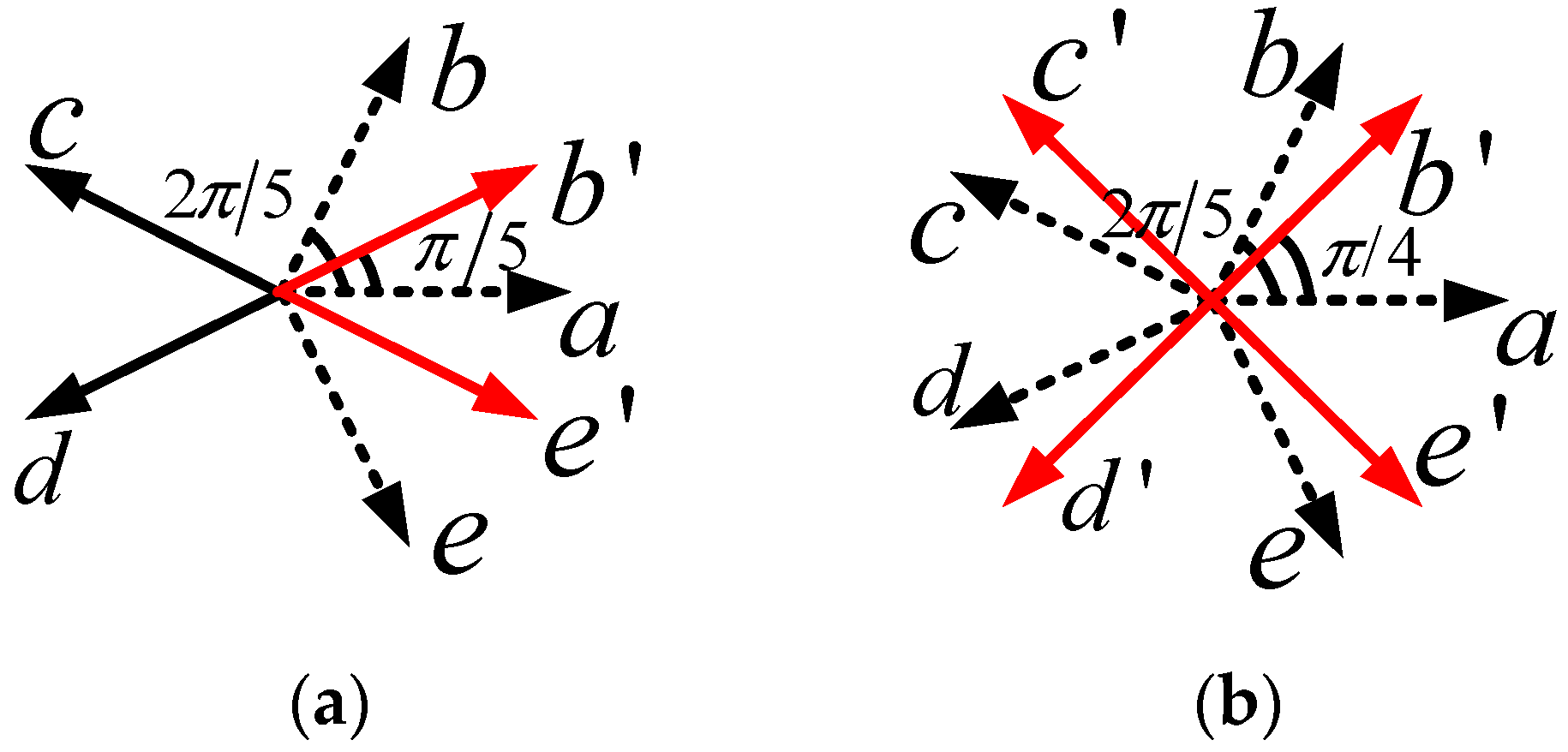
  • Analysis of the parameter α1. α1 is the electrical angle from α-axis to phase B counterclockwise.

3.1. Voltage Vector Matrices

Assuming single open-circuit fault happens on phase A, the voltage reduced-order transformation matrix derived from (3) can be further expressed as (6):
[ U α 1 U β 1 U α 3 U β 3 0 ] = 2 5 [ cos α 1 cos α 2 cos α 3 cos α 4 sin α 1 sin α 2 sin α 3 sin α 4 cos 3 α 1 cos 3 α 2 cos 3 α 3 cos 3 α 4 sin 3 α 1 sin 3 α 2 sin 3 α 3 sin 3 α 4 1 1 1 1 ] [ U b U c U d U e ]
where α1, α2, α3 and α4 are the electrical angles from α-axis to phase B, phase C, phase D, and phase E counterclockwise.
Substituting (1) and (2) into (6), the decoupled voltage matrix of α-axis can be expressed as follows:
[ U α 1 U α 3 ] = 2 5 [ 1 4 U a + U d c [ cos α 1 S b + cos α 2 S c + cos α 3 S d + cos α 4 S e + 1 4 ( S b + S c + S d + S e ) ] + ( cos α 1 + cos α 2 + cos α 3 + cos α 4 + 1 ) ( U N N 1 2 U d c ) 1 4 U a + U d c [ cos 3 α 1 S b + cos 3 α 2 S c + cos 3 α 3 S d + cos 3 α 4 S e + 1 4 ( S b + S c + S d + S e ) ] + ( cos 3 α 1 + cos 3 α 2 + cos 3 α 3 + cos 3 α 4 + 1 ) ( U N N 1 2 U d c ) ]

3.2. Matrices Simplification

In this case, in order to keep the magnetomotive force unchanged, shifts of voltage phasors have to be taken into consideration. Hence, values of parameters α1, α2, α3 and α4 are diverse, which differs from constant value of α = 2π/5. Since the parameters α1, α2, α3 and α4 lack a fixed relationship, it is still difficult to simplify (7). In order to establish the fixed relationship among α1, α2, α3 and α4, cosine function rule with electrical angles αx (0 < αx < 2π) is depicted as Figure 1. It is benefit to simplify (7) when the sum of α1 and α4 is equal to 2π and the sum of α2 and α3 is equal to 2π. As shown in Figure 1, cosα1 is equal to cosα4 and cosα2 is equal to cosα3 in this case. As a result, voltage phasors are symmetrical by α-axis.
Then, the voltage reduced-order transformation matrix can be expressed as (8).
[ U α 1 U β 1 U α 3 U β 3 0 ] = 2 5 [ c 1 c 2 c 2 c 1 s 1 s 2 s 2 s 1 c 2 c 1 c 1 c 2 s 2 s 1 s 1 s 2 1 1 1 1 ] [ U b U c U d U e ]
where c1 = cosα1, c2 = cosα2, s1 = sinα1, s2 = sinα2 and α1, α2 satisfy 0 < α1 < π/2, π/2 < α2 < π, respectively.
Substituting (1) and (2) into (8), the decoupled voltage matrix of α-axis can be expressed as follows:
[ U α 1 U α 3 ] = 2 5 [ 1 4 U a + U d c [ c 1 S b + c 2 S c + c 2 S d + c 1 S e + 1 4 ( S b + S c + S d + S e ) ] + ( c 1 + c 2 + 1 2 ) ( 2 U N N U d c ) 1 4 U a + U d c [ c 2 S b + c 1 S c + c 1 S d + c 2 S e + 1 4 ( S b + S c + S d + S e ) ] + ( c 1 + c 2 + 1 2 ) ( 2 U N N U d c ) ]
In order to further simplify the voltage vector matrix of α-axis, (9) can be divided into two components, as follows:
[ U α 1 _ b a s i c U α 3 _ b a s i c ] = 2 5 [ U d c ( c 1 S b + c 2 S c + c 2 S d + c 1 S e ) U d c ( c 2 S b + c 1 S c + c 1 S d + c 2 S e ) ]
[ U α 1 _ r e m a i n i n g U α 3 _ r e m a i n i n g ] = 2 5 [ 1 4 [ U a + U d c ( S b + S c + S d + S e ) ] + ( c 1 + c 2 + 1 2 ) ( 2 U N N U d c ) 1 4 [ U a + U d c ( S b + S c + S d + S e ) ] + ( c 1 + c 2 + 1 2 ) ( 2 U N N U d c ) ]
where Uα1_basic and Uα1_remaining are termed as the basic and remaining components of the voltage vector matrix of α-axis in the fundamental plane, respectively. Similarly, the parameters Uα3_basic and Uα3_remaining are the basic and remaining components in the harmonic plane.
Then, different values of α1 and α2 are substituted into (10) and (11). When the values of α1 and α2 are satisfied with (12), voltage phasors are symmetrical by β-axis and (13) is obtained in the form of equality.
α 2 = π α 1
c 1 + c 2 = cos α 1 + cos ( π α 1 ) = 0
Also, it can be found that (11) is simplified to zero and (9) is equal to (10). Thus, the voltage matrix on α1-β1 and α3-β3 spaces can be simplified as:
[ U α 1 U β 1 U α 3 U β 3 ] = 2 5 [ U d c ( c 1 S b + c 2 S c + c 2 S d + c 1 S e ) U d c ( s 1 S b + s 2 S c s 2 S d s 1 S e ) U d c ( c 2 S b + c 1 S c + c 1 S d + c 2 S e ) U d c ( s 2 S b + s 1 S c s 1 S d + s 2 S e ) ]
where c1 = cosα1, c2 = cos(π − α1), s1 = sinα1 and s2 = sin(π − α1).
As calculated by (14), post-fault voltage vector diagrams of the generalized five-phase SVPWM fault-tolerant control are obtained, as shown in Figure 2.

3.3. Vector Selection and Operation Time Calculation

In order to further investigate the generalized five-phase SVPWM fault-tolerant control, the appropriate voltage vectors will be selected and operation time will be calculated based on the simplified post-fault voltage vector matrices and diagrams. When an open-circuit fault occurs in phase A, Sa is invalid, since the five-phase inverter has been a four-phase one. Besides, there are only 24 = 16 different switching states after fault, while there are 25 = 32 switching states before fault. During fault-tolerant condition, the values of 16 voltage vectors can be derived. It can be calculated by (15) that the amplitudes of voltage vectors U5 (0101) and U10 (1010) are zero. However, the currents of U5 and U10 are not zero from phase B to phase E. Thus, both vectors U5 and U10 are not really zero vectors. Also, they are not suitable to compose the reference vector.
U x = 2 5 U d c [ S b e j α + S c e j ( π α ) + S d e j ( π α ) + S e e j α ]
where Ux is the values of voltage vectors. Twelve non-vanishing and two vanishing vectors can be utilized, except for U5 and U10. Each sector selects three non-vanishing vectors and two vanishing vectors to compose the reference vector. The first and last vector is U5 or U10, respectively. For example, the reference vector is composed by three non-vanishing vectors U8 (1000), U9 (1001) and U13 (1101), and two vanishing vectors U0 (0000) and U15 (1111) in sector 1. Moreover, assuming actuation durations of vectors U8, U9 and U13 are t1, t2, and t3, the relationships among them and reference vector can be given as (16) according to the sine thermo.
U r e f sin ( π α 1 ) = t 1 T s U 8 + t 3 T s U 13 sin θ = t 2 T s U 9 sin ( α 1 θ )
where Uref is the reference vector, Ts is the period of the pulse-width modulation, and θ is the angle between U9 and Uref.

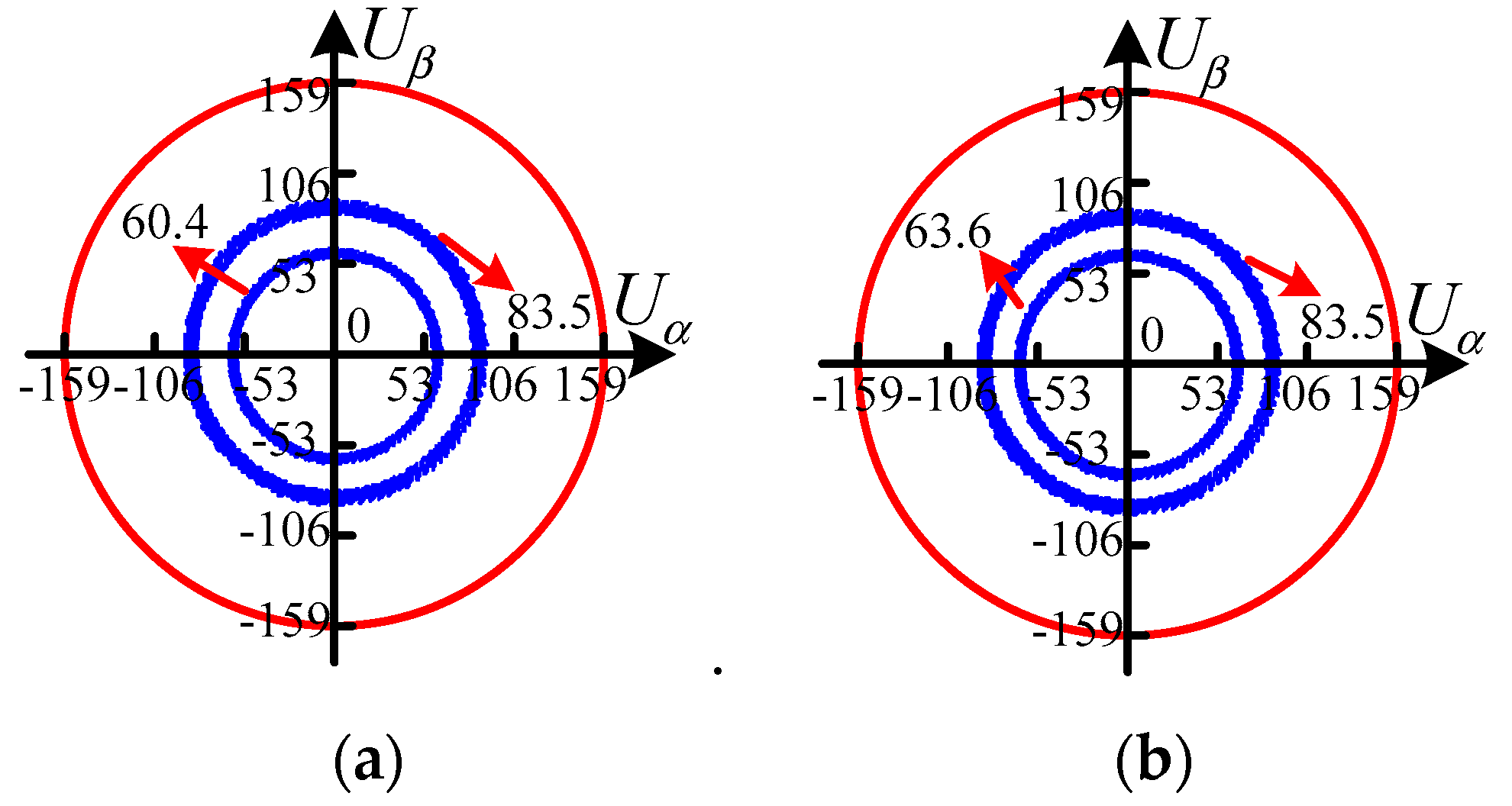
3.4. Influence of Parameter α1 on DC-Bus Voltage Utilization and Harmonic Current Suppression

By utilizing the generalized five-phase SVPWM fault-tolerant control, various SVPWM fault-tolerant control strategies with different values of parameter α1 can be obtained. However, several previous studies investigate the fault-tolerant control by quoting the idea of current hysteresis band pulse-width modulation fault-tolerant control [19] called the traditional strategy, which the parameter α1 is fixed to π/5 (36°). Obviously, this analogy has less generality.
On one hand, since the cost of DC power supply with a large capacity is expensive, low DC-bus voltage utilization is lack of economy in motor drive system. However, it is difficult for fault-tolerant control to maintain voltage utilization with fewer irregular vectors compared with normal control. In detail, vector diagrams of the five-phase SVPWM strategy have uniform sector size and cover three different sizes of non-vanishing vector: 0.6472Udc, 0.4Udc and 0.2472Udc. As revealed in [20], voltage utilization can be represented by the inscribed circle radius of regular decagon for the SVPWM strategy, as shown in Figure 3a. When the adjacent four vectors SVPWM strategy is adopted, the maximum value of voltage utilization Umax is equal to 0.5257Udc. However, vector diagram of the generalized five-phase SVPWM fault-tolerant control strategy is probably more irregular than that of the normal control strategy which has chaotic sectors. Similarly, as shown in Figure 3b, voltage utilization can be represented by the inscribed circle radius of diamond for the generalized fault-tolerant control strategy.
On the other hand, since the harmonics increase copper loss and decrease efficiency, specific analysis process of harmonics suppression is presented on post-fault voltage vector diagrams, as shown in Figure 4. Differing from vector diagrams on the SVPWM control strategy, not all vectors on α1-β1 space can be mapped to the α3-β3 space on fault-tolerant control strategies. For example, although U3 and U12 are utilized to compose reference vector on the α1-β1 space, they are absent from the α3-β3 space. As a result, there are only ten vectors remained except for U0, U3, U5, U10, U12 and U15.
Harmonic suppression is influenced by two parts. Firstly, applying times of vectors are analyzed. As shown in Figure 4b, third-harmonic component of voltage can be divided into α-axis and β-axis components, respectively. In the following discussion, Sector 1 is taken as an example. Since the amplitudes of voltage vectors U8 and U13 are equal, the β-axis component of third-harmonic voltage can be eliminated when t1 is equal to t3 as follows:
t 1 = t 3
Although the β-axis component of third-harmonic voltage can be suppressed by appropriate vector applying time, the α-axis component of the third-harmonic voltage is difficult to suppress using (17) on α3-β3 space [21]. Secondly, locations of vectors are further analyzed. U9 should be as short as possible and the angle between U8 and β-axis should be as narrow as possible.
Based on the rules of voltage utilization calculation and harmonic current suppression above, different values of the parameter α1 are introduced into voltage vector diagrams. The relationships of voltage utilization and third-harmonic component with different values of the parameter α1 (0 < α1 < π/2(90°)) can be drawn, as shown in Figure 5. It can be observed that the parameter α1 has a great impact on voltage utilization and harmonics suppression. When the angle of α1 is close to π/4 (45°), it is benefit to improve voltage utilization. In addition, when the angle of α1 is as large as possible, it is benefit to suppress harmonic components. Thus, giving consideration to the two aspects, the α1 = π/4 (45°) control strategy is select for further investigated.

4. Comparison and Evaluation

According to analysis of the generalized five-phase SVPWM fault-tolerant control strategy and inference of the parameter α1, the improved SVPWM fault-tolerant control strategy (α1 = π/4) is derived, which will be compared with the traditional SVPWM fault-tolerant control strategy (α1 = π/5) in terms of voltage vector diagrams, voltage utilization and harmonics suppression.

4.1. Comparison of Voltage Vectors

Figure 6 presents the pre- and post-fault basic space vectors of the traditional and improved control strategies. As shown in Figure 6a, it can be found that the phasor angles of phases B and E shift π/5, while phases C and D remain the original position. In addition, as shown in Figure 6b, it can be found that all non-fault phasor angles are adjusted. In detail, the phasor angles of phases B and E shift 3π/20, while the phasor angles of phases C and D shift π/20.
As calculated by (14), vector diagrams of the traditional control strategy can be obtained which have chaotic sizes of sectors and cover three different sizes of non-vanishing vector: 0.6472Udc, 0.4Udc and 0.4702Udc. Unlike the cases of the traditional control strategy, vector diagrams of the improved control strategy have uniform size of sectors and cover only two different sizes of non-vanishing vector: 0.5657Udc and 0.4Udc.

4.2. Comparison of DC-Bus Voltage Utilization

As described in Figure 7, the maximum values of DC-bus voltage utilization Umax can be represented by the inscribed circle radius of diamond based on five-phase motor with single-phase open-circuit fault. In detail, the maximum value of voltage utilization Umax is equal to 0.38Udc when the traditional fault-tolerant control strategy is adopted, as shown in Figure 7a. Compared with the traditional fault-tolerant control strategy, the improved fault-tolerant control strategy possesses higher DC-bus voltage utilization, which is up to 0.4Udc as shown in Figure 7b. Hence, the improved control strategy is superior to the traditional control strategy on DC-bus voltage utilization.

4.3. Comparison of DC-Bus Voltage Utilization

Since third-harmonic take account for the main proportion in total harmonic distortion in the five-phase motor with single-phase open-circuit fault, the third-harmonic component is analyzed as shown in Figure 8, where the third-harmonic component is represented by the length of composed reference vector mapped on the α3-β3 space.
In detail, the length of composed reference vector mapped on the α3-β3 space can be calculated by (18) when the traditional fault-tolerant control strategy is adopted as shown in Figure 8a. Also, as calculated by (19), the improved fault-tolerant control strategy offers lower third-harmonic component as compared with the traditional fault-tolerant control strategy, as shown in Figure 8b.
U α 3 _ t r a _ r e f = 0.6472 U d c + 0.3236 U d c 2 = 1.2944 U d c
U α 3 _ i m p _ r e f = 0.5657 U d c + 0.2829 U d c 2 = 1.1314 U d c
where Uα3_tra_ref and Uα3_imp_ref are termed as the length of composed reference vector mapped in the α3-β3 space in sector 1 with the traditional and improved control strategies, respectively. Clearly, the result of (19) is smaller than that of (18). It can be verified that the results above can be transplanted to all sectors. Hence, the improved control strategy is superior to the traditional control strategy on harmonic suppression.

5. Simulation and Experimental Verification

5.1. Simulation

As shown in Figure 9, the control system for a five-phase PM motor is established, where the fault-tolerant SVPWM generator is the core of the system for fault tolerant operation. The main simulation parameters are listed in Table 1.
Figure 10, Figure 11, Figure 12 and Figure 13 compare the simulated results of the traditional (α1 = π/5) and improved (α1 = π/4) control strategies from normal SVPWM to fault-tolerant SVPWM. After open-circuit fault occurs at 0.1 s on phase A, the current of phase A becomes 0 A suddenly. Firstly, torque performances of two fault-tolerant control strategies are evaluated, as shown in Figure 10. It can be found that torque ripple of the improved control strategy is relatively lower than that of the traditional control strategy. Secondly, current waveforms of two fault-tolerant control strategies are compared, as shown in Figure 11. Obviously, it can be seen that the amplitudes of phase currents on both fault-tolerant control strategies increase. Thirdly, as shown in Figure 12, by Fast Fourier Transform analysis of simulated fault-tolerant current waveforms, it is shown that the amplitudes of fundamental waves with both fault-tolerant control strategies are similar. Also, it should be noted that the total harmonic distortion of the improved control strategy is lower than the traditional one. Finally, the DC-bus voltage utilizations with the two fault-tolerant control strategies are presented in Figure 13. The inner trace and the middle circle represent the output voltage of the motor under the fault-tolerant and normal condition, where the outer circle reflects on DC-bus voltage. Hence, it can be concluded that the improved control strategy can offer good performance on better harmonics suppression and higher voltage utilization than the traditional control strategy based on the simulated results.

5.2. Experimental Results

In order to further verify the theoretical results, a five-phase PM motor drive with a type of TMS320F2812-based digital signal processor is built, as shown in Figure 14. Experiments are carried out under non-rated condition limited by maximum capacity of inverter and torque sensor. During the experiment, the reference rotating speed and the initial load are set to 120 r/min and 5.6 Nm. Also, the DC-bus voltage is set as 27 V.
Firstly, measured torque and currents of the motor with normal control strategy, traditional (α1 = π/5), and improved (α1 = π/4) fault-tolerant control strategies for phase A being open-circuit fault are compared, as shown in Figure 15. It can be observed that the motor with fault remains almost the same average torque as that of normal control strategy by utilizing the generalized five-phase SVPWM fault-tolerant strategy, albeit with increasing a few torque ripples and phase current amplitudes. Hence, it can be verified that the generalized strategy is beneficial for the motor drive to offer high fault-tolerant capability. As presented in simulation results, phases C and E suffer from higher total harmonic distortion than other phases when the fault-tolerant control strategy are applied. Thus, the two phase currents are analyzed in experiments. Figure 15b,c gives the measured currents of phases C and E. It can be seen that with the improved (α1 = π/4) control strategy, phase current harmonics are reduced as compared to that of the traditional (α1 = π/5) control strategy.
Secondly, by Fast Fourier Transform analysis of measured fault-tolerant current waveforms of phases C and E, it can be clearly verified that total harmonic distortion of the phase current of the improved control strategy is lower than the traditional control strategy, as shown in Figure 16. Besides, the amplitudes of fundamental waves of the two fault-tolerant control strategies are similar.
Finally, the voltage utilizations of the traditional and improved fault-tolerant control strategies are measured, as shown in Figure 17. It can be found that the improved control strategy offers higher voltage utilization than the traditional control strategy.

6. Conclusions

In this paper, an improved SVPWM fault-tolerant control strategy for a five-phase PM motor has proposed to deal with the loss of one phase. Compared with the traditional matrices analysis method with the fixed α1 = π/5, the matrices analysis method in this paper effectively extend the feasible matrices under the fault tolerant condition by adjusting the parameter α1. Then, generalized five-phase SVPWM fault-tolerant control has deduced and analysed, which yields a greatly increased capacity to enhance fault-tolerant performances of the motor. Also, various SVPWM fault-tolerant control strategies with different values of the parameter α1 can be deduced. It is found that the parameter α1 has a great impact on harmonic current suppression and DC-bus voltage utilization. Then, giving consideration to both two aspects of the harmonic current suppression and DC-bus voltage utilization, an improved fault-tolerant control strategy with α1 = π/4 has been proposed. In addition, the improved control strategy (α1 = π/4) has been compared with the traditional control strategy (α1 = π/5). It is shown that the improved control strategy offers lower current harmonics and higher voltage utilization. Both simulation and experimental results have verified the proposed control strategy. In the future, new fault tolerant control will be considered to further reduce current harmonics and improve efficiency of the motor system.

Author Contributions

Conceptualization, L.X. and W.Z.; methodology, L.X.; software, L.X.; validation, L.X.; formal analysis, L.X.; investigation, L.X., G.L. and W.Z.; resources, L.X., G.L. and W.Z.; data curation, L.X.; writing—original draft preparation, L.X.; writing—review and editing, W.Z. and G.L.

Funding

This work was supported in part by the National Natural Science Foundation of China under grants 51807082 and 51877098, in part by the Key Research and Development Program of Jiangsu Province under grant BE2018107, in part by China Postdoctoral Science Foundation under grant 2018M642179, and in part by Priority Academic Program Development of Jiangsu Higher Education Institutions.

Conflicts of Interest

The authors declare no conflict of interest.

References

  1. Lee, C.H.T.; Angle, M.; Bhalla, K.K.; Qasim, M.; Mei, J.; Mohammadi, S.; Iyer, K.L.V.; Sinkular, J.J.; Kirtley, J.L. Quantitative comparison of vernier permanent-magnet motors with interior permanent-magnet motor for hybrid electric vehicles. Energies 2018, 11, 2546. [Google Scholar] [CrossRef] [Green Version]
  2. Shi, Y.; Jian, L. A novel dual-permanent-magnet-excited machine with flux strengthening effect for low-speed large-torque applications. Energies 2018, 11, 153. [Google Scholar] [CrossRef] [Green Version]
  3. Yang, H.; Lin, H.; Zhu, Z.Q.; Lyu, S.; Liu, Y. Design and analysis of novel asymmetric-stator-pole flux reversal pm machine. IEEE Trans. Ind. Electron. 2020, 67, 101–114. [Google Scholar] [CrossRef] [Green Version]
  4. Zheng, P.; Wu, F.; Lei, Y.; Sui, Y.; Yu, B. Investigation of a novel 24-slot/14-pole six-phase fault-tolerant modular permanent-magnet in-wheel motor for electric vehicles. Energies 2013, 6, 4980–5002. [Google Scholar] [CrossRef]
  5. Sui, Y.; Zheng, P.; Yin, Z.; Wang, M.; Wang, C. Open-circuit fault-tolerant control of five-phase PM machine based on reconfiguring maximum round magnetomotive force. IEEE Trans. Ind. Electron. 2018, 66, 48–59. [Google Scholar] [CrossRef]
  6. Wang, B.; Wang, J.; Griffo, A.; Sen, B. Experimental Assessments of a triple redundant nine-phase fault-tolerant PMA SynRM drive. IEEE Trans. Ind. Electron. 2019, 66, 772–783. [Google Scholar] [CrossRef] [Green Version]
  7. Chen, Q.; Xu, G.; Liu, G.; Zhao, W.; Liu, L.; Lin, Z. Torque ripple reduction in five-phase interior permanent magnet motors by lowering interactional MMF. IEEE Trans. Ind. Electron. 2018, 65, 8520–8531. [Google Scholar] [CrossRef]
  8. Wang, W.; Zhang, J.; Cheng, M. Line-modulation-based flux-weakening control for permanent-magnet synchronous machines. IET Power Electron. 2018, 11, 930–936. [Google Scholar] [CrossRef]
  9. Zhou, Y.; Yan, Z.; Duan, Q.; Wang, L.; Wu, X. Direct torque control strategy of five-phase PMSM with load capacity enhancement. IET Power Electron. 2018, 12, 598–606. [Google Scholar] [CrossRef]
  10. Tian, B.; An, Q.T.; Duan, J.D.; Sun, D.Y.; Sun, L.; Semenov, D. Decoupled modeling and nonlinear speed control for five-phase PM motor under single-phase open fault. IEEE Trans. Power Electron. 2017, 32, 5473–5486. [Google Scholar] [CrossRef]
  11. Wang, W.; Zhang, J.; Cheng, M. Common model predictive control for permanent-magnet synchronous machine drives considering single-phase open-circuit fault. IEEE Trans. Power Electron. 2017, 32, 5862–5872. [Google Scholar] [CrossRef]
  12. Sen, B.; Wang, J. Stationary frame fault-tolerant current control of polyphase permanent-magnet machines under open-circuit and short-circuit faults. IEEE Trans. Power Electron. 2016, 31, 4684–4696. [Google Scholar]
  13. Xu, L.; Liu, G.; Zhao, W.; Yang, X.; Cheng, R. Hybrid stator design of fault-tolerant permanent-magnet vernier machines for direct-drive applications. IEEE Trans. Ind. Electron. 2017, 64, 179–190. [Google Scholar] [CrossRef]
  14. Zhao, W.; Chen, Z.; Xu, D.; Ji, J.; Zhao, P. Unity power factor fault-tolerant control of linear permanent-magnet vernier motor fed by a floating bridge multilevel inverter with switch fault. IEEE Trans. Ind. Electron. 2018, 65, 9113–9123. [Google Scholar] [CrossRef]
  15. Mohammadpour, A.; Mishra, S.; Parsa, L. Fault-tolerant operation of multiphase permanent-magnet machines using iterative learning control. IEEE J. Emerg. Sel. Top. Power Electron. 2014, 2, 201–211. [Google Scholar] [CrossRef]
  16. Chai, M.; Xiao, D.; Dutta, R.; Fletcher, J.E. Space vector PWM techniques for three-to-five-phase indirect matrix converter in the overmodulation region. IEEE Trans. Ind. Electron. 2016, 63, 550–561. [Google Scholar] [CrossRef]
  17. Xia, Y.; Zhang, X.; Qiao, M.; Yu, F.; Wei, Y.; Zhu, P. Research on a new indirect space-vector overmodulation strategy in matrix converter. IEEE Trans. Ind. Electron. 2016, 63, 1130–1141. [Google Scholar] [CrossRef]
  18. Zhou, C.; Yang, G.; Su, J. PWM strategy with minimum harmonic distortion for dual three-phase permanent-magnet synchronous motor drives operating in the overmodulation region. IEEE Trans. Power Electron. 2016, 31, 1367–1380. [Google Scholar] [CrossRef]
  19. Liu, G.; Qu, L.; Zhao, W.; Chen, Q.; Xie, Y. Comparison of two SVPWM control strategies of five-phase fault-tolerant permanent-magnet motor. IEEE Trans. Power Electron. 2016, 31, 6621–6630. [Google Scholar] [CrossRef]
  20. Chen, K.Y.; Xie, Y.L. Reducing harmonics distortion in five-phase VSI using space-vector-based optimal hybrid PWM. IEEE Trans. Power Electron. 2017, 32, 2098–2113. [Google Scholar] [CrossRef]
  21. Bermudez, M.; Gonzalez-Prieto, I.; Barrero, F.; Guzman, H.; Duran, M.J.; Kestelyn, X. Open-phase fault-tolerant direct torque control technique for five-phase induction motor drives. IEEE Trans. Ind. Electron. 2017, 64, 902–911. [Google Scholar] [CrossRef] [Green Version]
Figure 1. Cosine function diagram of electrical angles αx (0 < αx < 2π).
Energies 12 04626 g001
Figure 2. Generalized post-fault voltage vector diagrams: (a) α1-β1 space; (b) α3-β3 space.
Energies 12 04626 g002
Figure 3. DC-bus voltage utilization under different control strategies: (a) normal control strategy; (b) generalized fault-tolerant control strategy.
Energies 12 04626 g003
Figure 4. Analysis of harmonics suppression in post-fault voltage vector diagrams: (a) α1-β1 space; (b) α3-β3 space.
Energies 12 04626 g004
Figure 5. Relationships of voltage utilization and third-harmonic component with parameter α1 (0 < α1 < π/2(90°)): (a) voltage utilization (% of Udc) curve; (b) third-harmonic component (p.u. value of Udc) curve. Note: Udc = direct current bus voltage; p.u. = per unit.
Energies 12 04626 g005
Figure 6. Locations of pre- and post-fault basic space vectors: (a) traditional control strategy (α1 = π/5); (b) improved control strategy (α1 = π/4).
Energies 12 04626 g006
Figure 7. DC-bus voltage utilization on different SVPWM fault-tolerant control strategies: (a) traditional control strategy (α1 = π/5); (b) improved control strategy (α1 = π/4).
Energies 12 04626 g007
Figure 8. Analysis of harmonic suppression on post-fault voltage vector diagrams: (a) traditional control strategy (α1 = π/5); (b) improved control strategy (α1 = π/4).
Energies 12 04626 g008
Figure 9. Control block diagram of the fault-tolerant system. Note: SVPWM = space vector pulse width modulation; PI = proportional plus integral controller.
Energies 12 04626 g009
Figure 10. Simulated torque waveforms: (a) traditional control strategy (α1 = π/5); (b) improved control strategy (α1 = π/4).
Energies 12 04626 g010
Figure 11. Simulated current waveforms: (a) traditional control strategy (α1 = π/5); (b) improved control strategy (α1 = π/4).
Energies 12 04626 g011
Figure 12. Fast Fourier transform analysis of simulated fault-tolerant current waveforms: (a) fundamental (210 Hz); (b) total harmonic distortion.
Energies 12 04626 g012
Figure 13. Simulated voltage utilization trajectories: (a) traditional control strategy (α1 = π/5); (b) improved control strategy (α1 = π/4).
Energies 12 04626 g013
Figure 14. Experimental platform: (a) motor test and drive control device; (b) computer and input/output device.
Energies 12 04626 g014
Figure 15. Measured torque (trace 4) and currents of phase A (trace 1), C (trace 2), and E (trace 3) under different conditions (100 ms/div, 4 Nm/div, and 5 A/div): (a) normal control strategy; (b) traditional fault-tolerant control strategy (α1 = π/5); (c) improved fault-tolerant control strategy (α1 = π/4).
Energies 12 04626 g015
Figure 16. Fast Fourier transform analysis of measured fault-tolerant current waveforms: (a) fundamental (42 Hz); (b) total harmonic distortion.
Energies 12 04626 g016
Figure 17. Measured DC-bus voltage utilization trajectories: (a) traditional fault-tolerant control strategy (α1 = π/5); (b) improved fault-tolerant control strategy (α1 = π/4).
Energies 12 04626 g017
Table 1. Motor drive parameters.
SymbolSimulation Parameters/UnitsValues
NpmNumber of permanent magnet pole pairs21
IsStator current rms/A10
nRotating speed/(r/min)600
TeAverage torque/(Nm)38
UdcDC-bus voltage/(V)159

