Article

Development of a Control Platform for a Building-Scale Hybrid Solar PV-Natural Gas Microgrid

by
Parhum Delgoshaei
1,* and
James D. Freihaut
2
1
Engineering Division, Penn State Great Valley, Malvern, PA 19355, USA
2
Department of Architectural Engineering, Penn State, University Park, Philadelphia, PA 16802, USA
*
Author to whom correspondence should be addressed.
Energies 2019, 12(21), 4202; https://doi.org/10.3390/en12214202
Submission received: 8 September 2019 / Revised: 15 October 2019 / Accepted: 16 October 2019 / Published: 4 November 2019

Abstract

:
Building-scale microgrids are a type of behind-the-meter microgrids where the building operator has control of the distributed energy resources, including, in this case, a natural gas-fired microturbine in addition to solar PV and battery energy storage systems. There is a growing trend in deploying behind-the-meter microgrids due to their benefits including the resiliency of serving critical loads, especially in regions with abundant natural gas. In order to ensure distributed energy resources are dispatched optimally for the desired mode of operation, a hierarchical control platform including a centralized controller was developed and installed. The platform includes communication and control infrastructure that interface with controllers for distributed energy resources and the building automation system of a recently built energy efficient commercial building. Based on desirable outcomes under different grid and building conditions, operational modes were defined for the microgrid controller. The controller is programmed to map each mode to respective operational modes for distributed energy resources controllers. Experimental data for test runs corresponding to two operational modes confirm the communication and control infrastructure can execute hierarchical control commands. Finally, dispatch optimization for a year-long simulation of system operation is presented and the benefits of the hybrid solar PV-natural gas setup are evaluated.

Graphical Abstract

1. Introduction

Microgrids are electricity distribution systems containing loads and distributed energy resources (such as distributed generators, storage devices, or controllable loads) that can be operated in a controlled, coordinated way either while connected to the main power network or while islanded [1]. Integrating distributed energy resources (DERs) including renewable sources such as solar PV, nonrenewable sources such as natural gas-powered microturbines, and energy storage in the boundaries of a microgrid (behind-the-meter) in the low voltage (LV) and (MV) scale can potentially provide a large number of benefits to the main power utility by increasing its efficiency of operation and to the customer by improving reliability and quality of service [2].
Reductions in solar photovoltaic (PV) installation costs [3,4] have made it a viable, albeit intermittent DER when favorable interconnection conditions exist and space is available. Factoring in short-term stochastic variability of the solar resource (such as passing clouds) leads to a 6% to 15% decrease in capacity values for solar PV as a DER [5]. Forecasting approaches have been proposed [6,7,8], and [9] to predict the variability of the solar resource and assist in more accurate sizing of system components including battery energy storage systems that are integrated as a DER to compensate for the intermittency of renewables among other reliability and resiliency benefits that they provide [10,11,12]. Although non-renewable DERs such as natural gas lack the carbon reduction benefits, in situations that continuity of serving the load can be economically justified, they offer added reliability and resiliency and added energy efficiency benefits when they are utilized in combined heat and power (CHP) applications as they don’t suffer from the intermittency of renewables [13,14].
The benefits of combining availability of renewable resources, battery energy storage systems to mitigate their intermittency, and natural gas microturbines with reliable dispatchability as DER resources of a microgrid can be best realized when the deployment and dispatch command for each DER is controlled behind the meter in coordination with managing the load of the microgrid, however, come at cost of the challenges associated with local control and dispatch of these DERs.
With reductions in the cost of DER installations and the increased value placed on the benefits of integrating them in industrial, military, academic, and commercial microgrids (“behind-the-meter” campus/community-scale microgrids), increasingly these facilities have operated their DERs using their microgrid control systems [15,16,17,18,19,20]. On a smaller scale, the same concept has been implemented on a low-voltage (LV) scale in the confines of a single building. For example, in [21], monitoring and control of solar PV, a microturbine, and battery energy storage as DERs of a low voltage microgrid in a university laboratory setup are documented. Authors in [22] demonstrate controlling the operation of an LV microgrid consisted of a generator and battery energy storage, and in [23], the dynamics of operating a microturbine in an LV network are simulated. In [24], the dynamics of operating a microturbine and a battery energy storage system are studied; this does not cover how those DERs interact with a building as their load.
While these microgrids have many similarities to their larger community-scale counterparts, a common observation of these systems as a representative of LV microgrids is that they are experimental setups and do not serve main building loads. An exception is [25], where the operation of both renewable and non-renewable DERs in an LV microgrid is covered in both islanded and grid-connected setups although the analysis is limited to electrical variables (voltage and frequency) and not how the control system manages DER power generation and load power consumption. There is a need to study how the control platform in building-scale microgrids can perform energy management for renewable and non-renewable energy resources, battery energy storage, building loads, and electric utility at the same time. The building-scale microgrid associated with the control platform in this paper fills this knowledge gap in the context of demonstrating how all DERs can be controlled for a common application (i.e., demand curtailment).
It should be noted that in the smaller building-scale microgrids, the communication and control infrastructure is dependent upon interfacing building-level controls with controls utilized in distributed generation such as inverters and microturbines whereas the larger “feeder-level” microgrids rely on the mature communication and control infrastructure utilized in electrical distribution networks for years. Moreover, perhaps not surprising, economies of scale, including the collective efficiency and resiliency benefits of the DERs, work more in favor of community-scale microgrids. The main aim of this paper is to provide the details of developing a hierarchical control platform for a low-voltage, behind-the-meter building-scale microgrid in an energy-efficient commercial building from the central microgrid controller to renewable and non-renewable DERs and the battery energy storage system. In addition, test and simulation of the system in action is covered. In the following sections, the components, communication infrastructure, and control(simulated) resulting in the optimized dispatch of the DERs of this building-scale microgrid will be contrasted against the similar areas of their larger scale counterparts (feeder-level microgrids) to achieve an economic goal (demand peak reduction) and resiliency.
This paper is organized as follows: Section 2 covers microgrid communication and control. In Section 3, the building-scale microgrid implementation is presented. Section 4 covers the description of the components of the installed control platform for the microgrid, their function, and different system and component modes operation. Section 5 covers two tests of the control system and simulation of one of its modes of operation. Principal conclusions are drawn in Section 6. Future directions are finally discussed in Section 7.

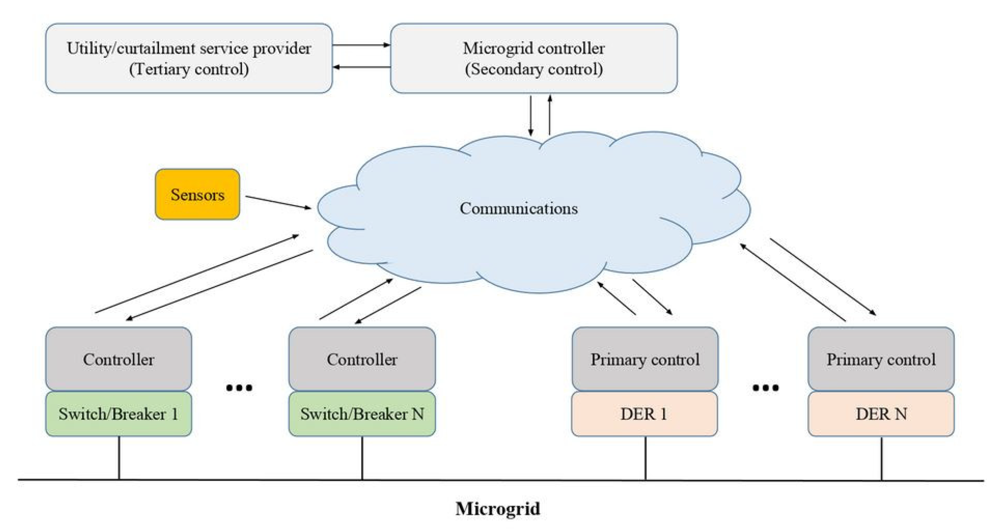
2. Hierarchical Control in Microgrids

In this section, we will cover why there are multiple conceptions of microgrid control in literature and how control is accomplished in different layers from the utility side all the way to the control of distributed energy resources. Using the terminology covered in this section, we will specify the control layers that the developed platform in this paper can execute in its current form and its extended form as additional funding is secured for the project (covered in the future directions section).

2.1. Functions of a Microgrid Controller

We should first clarify the functions that a controller can coordinate to be fulfilled [26], including the following five main functions:
  • Uninterruptible supply of sensitive loads
  • Seamless disconnection (island mode) and reconnection:
  • Delivery of active power and reactive power per the needs of the microgrid and/or the distribution system
  • DER operation per assigned set point within their operational limits
  • DER generation optimization while factoring in exchanges with the utility and market participation
These functions can be grouped into broad categories: those that are associated with connecting or disconnecting and stable operation (islanding) within a predefined time per standards (1 and 2) and those that are associated with assigning set points for DERs and loads (3, 4, and 5). When referencing microgrid control, a product [27,28], for example, or a scholarly work [29], as a sample, may refer to the first category (controlling connection/disconnection) as the function of a microgrid controller. Alternatively, scholarly works such as [30] (utilizing a dedicated controller in this category from the same vendor in [28]) subscribe to the second conception (controlling set points and optimizing DER operation) for a microgrid controller. The controller for this building-scale microgrid discussed, in Section 4, also falls in this category. Highlighting this distinction is important as each conception has its own design and implementation challenges which dictates the focus on the topics covered in the rest of this section.

2.2. Hierarchical Control Layers in Microgrids

A hierarchical control strategy is a common approach for controlling microgrids [26,31]. The first level in the hierarchy, primary control, is implemented in local controllers (also called primary controllers, Figure 1) of distributed energy resources (DERs) for controlling either voltage and frequency (in islanded mode)—characterized as “Primary Control-Power Sharing Control” in [31] or controlling active and reactive power (in grid-connected mode), characterized as “Primary Control-Inverter Output Control” in [31]. The secondary level, when implemented by a central controller as is the case in this work, is tasked with making decisions of the dispatch of DERs and serving loads, dictating their power set points, and economic optimization of the dispatch. It should be noted that the mapping of functions to hierarchy levels differs between authors. For example, [32] affixes the functions listed earlier as secondary control (also classified as such in [2,31]) to the tertiary level of the hierarchy.
Closely related to the primary-secondary-tertiary classification of the hierarchical layers of control [31], is the three-level delineation in [2] (Figure 2). The Microgrid Optimizer Layer in Figure 2 corresponds to functions in the secondary and tertiary levels. The Dispatch Layer corresponds to the secondary and primary levels (inverter output control). Finally, the Consortium for Electric Reliability Technology Solutions (CERTS) Autonomous Layer (discussed later in this paper) corresponds to the primary level (power-sharing control) and functions related to transition between grid-connected and islanded modes of operation including switches, disconnect devices, and protection. The three-layer approach of [2] will be adopted in this paper to describe the implementation of the control platform in Section 5 as this approach of grouping the layers of the hierarchy closely aligns with the current (Dispatch Layer) and future (Microgrid Optimizer, Section 7) state of the project. The challenges and benefits of a potential future implementation of the CERTS Autonomous Layer will be discussed in the context of the Microgrid Control States in Section 4. In the following, this layer will be briefly discussed.
During the stand-alone (islanded) mode of operation, voltage and frequency of the microgrid are no longer determined by the host grid and thus should be controlled by primary controllers (power-sharing control, [31]) of DERs—a control function complimentary to DERs primary controller (inverter output control, [31]) used to control real and reactive power levels in the grid-connected mode of operation. In the islanded mode, the central microgrid controller oversees load sharing mechanisms and communicates appropriate set points to different local low-level DER controllers and controllable loads. A small mismatch of the amplitude, phase angle or frequency of the output voltage of any DER unit can lead to a high circulating current. The implementation of Consortium for Electric Reliability Technology Solutions (CERTS) [18,19] microgrid concept has demonstrated how the reliability of a microgrid can be increased by enabling plug-and-play DER addition without extra communications. Each DER in a CERTS paradigm regulates voltage and frequency and balances real power through a power versus frequency droop controller (implemented in the primary controller of all DERs). To control the reactive power, a voltage versus reactive power droop controller is implemented in the primary controller of all DERs. In order for an inverter to operate in the CERTS paradigm, it would need to be able to operate as a voltage-source inverter and have a stable dc bus voltage during load transients [33]. In this project, this is ensured for the built-in microturbine inverter. While most grid-connected PV inverters are only capable of functioning as current-source inverters, the selected inverter in this project can cover this requirement and also operate as a voltage-source inverter (details of both to follow in Section 4).

2.3. Communications for Hierarchical Control

Since different microgrid control functions are mapped to the different levels of the hierarchy, which are implemented in different devices, including the microgrid controller, there should exist the means to carry control signals between them, especially between the microgrid controller and DERs.
Microgrids can be implemented in different scales based on their point of interconnection: full substation microgrid, full feeder microgrid, partial feeder microgrid, and single customer microgrid. Accordingly, they have different hardware integration and communication and control requirements. Although the foundation of a microgrid is based on lateral integration of its fundamental assets, intelligence in a smart microgrid is based on vertical integration of upper-layer applications with lower-layer components. For example, an application such as demand response may not be feasible without tight integration between assets functioning and the different layers of the hierarchy, which provide inputs and are influenced by the real-time status of the system. This tight integration is possible by a microgrid communication system utilizing different protocols at different layers.
At the highest level, a microgrid supervisory control and data acquisition (SCADA) [2] collects the real-time status and through interaction with the system operator, and the microgrid management software enables the microgrid to fulfill different applications such as load shedding, demand response, and islanding/reconnection. Different protocols enable communication between different microgrid layers as shown in Figure 3 [2].
As seen in Figure 1, in the lowest level (interaction with loads), the Open ADR (Open Automated Demand Response) is used for communication for the microgrid system in [2]. In the next level, Modbus is used for inverter and generator control systems and human machine interface (HMI). It can be transmitted over different communication links such as RS-232/RS-485 and ethernet. Moving up in the hierarchy, IEC 61850 is a substation automation standard. This relatively new standard has been touted as one of the key solutions to microgrid control and communication. As seen in Figure 3, the central gateway that implements microgrid control at the highest level (SCADA) communicates with the microgrid controller and individual DER controllers using the IEC 61850 protocol. This is the same approach followed by Eaton in implementing their microgrid controller, including the system installed at Fort Sill [2]. The next higher-level protocol is DNP3. The Distributed Network Protocol (DNP3) is mainly used in utilities such as electric and water companies. As seen in Figure 3, this protocol is key in enabling the electric utility to communicate with the microgrid controller. It is also the protocol used by PJM (PJM Interconnection, Valley Forge, PA, USA), a regional transmission organization overseeing electricity distribution in the USA, to share the frequency regulation signal with its customers. IEC 60870-5 (primarily used in Europe and the Middle East) is another SCADA protocol closely related to DNP3 (widely used in the U.S.) [34]. Compared to DNP3, the application layer in IEC 60870-5-104 is integrated with Transmission Control Protocol/Internet Protocol (TCP/IP) stack, allowing convenient solutions for interfacing server devices using this protocol with local Ethernet/IP networks [35].
Communication protocols utilized in microgrids including those listed earlier, rely on the underlying physical communication links, which are key to effective monitoring and control of DERs [2,36]. In addition to wired communication links that commonly enable protocols listed earlier in this section, wireless communication links have been introduced to smart grid and microgrid applications in recent years. In addition to wireless cellular technologies [2,37], there are two notable recent advances in this area. The first is combining wireless and power line carrier (PLC). This technology lends itself well to smart grid/microgrid data acquisition applications in rural or remote areas. While PLC works best for smaller distances, wireless can cover long distances with repeaters; however, unlike wireless, PLC is not impacted by weather or natural obstacles. As a result, the heterogeneous radio-PLC network was demonstrated to support stable communication over distances of kilometers without the necessity for repeaters [38]. Another recent advance in wireless technology that has found its way in smart grid and microgrid applications is the deployment of Low Power Wide Area Networks (LPWAN) [39] which in addition to being low power, offer long range, high capacity, and high quality of service connections between utilities and microgrid devices including DERs based on existing cellular long-term evolution (LTE) functionalities.
Historically, security concerns have been an impediment to utilizing wireless communication links in microgrid applications [2]. It is due to the importance of cybersecurity considerations that standards and recommendations such as IEC 62351, IEC 62443, and NIST 800-57 have been developed [40]. Their implementation, however, comes with a performance penalty, including bandwidth and delay issues that should be taken into account [41].
It should be noted that the three protocols listed earlier (DNP, IEC 61850 and 60870) are deployed primarily in the electrical distribution system and are not suitable for behind-the-meter adoption to carry control signals issued by the microgrid controller in the building. They were reviewed, however, as they should be relied upon in the context of any future interactions between a curtailment service provider (CSP) or the utility with the microgrid controller in the context of tertiary control. The authors in [37,42] share the architectures, information exchange details, technical communication details, and organizational guidelines to establish such interactions. In Section 4, more details on the communication network that enables the microgrid controller to communicate with DER primary controllers behind the meter are discussed.
Before contextualizing this review of microgrid hierarchical control and associated communications in the developed control platform for the building-scale microgrid (Section 5), we will first discuss in the next section, the sources and sinks of energy in the microgrid: the building, distributed energy resources, and battery energy storage systems.

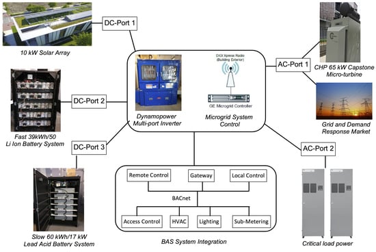
3. Microgrid Components and Layout

The Penn State Building 7R microgrid system consists of the following components: a natural gas-fueled Capstone 65 kW microturbine which is capable of generating both electricity and hot water, 10 kW solar photovoltaic array, lead-acid and lithium-ion battery banks, a ‘smart’ inverter, a microcontroller, and a weather station. It is designed to operate both in tandem with the electric grid, as well as independently in ‘islanded’ mode (simulating a grid outage). Figure 4 shows the interaction of different components in the 7R microgrid. The description of the building and these components are covered in the following subsections.

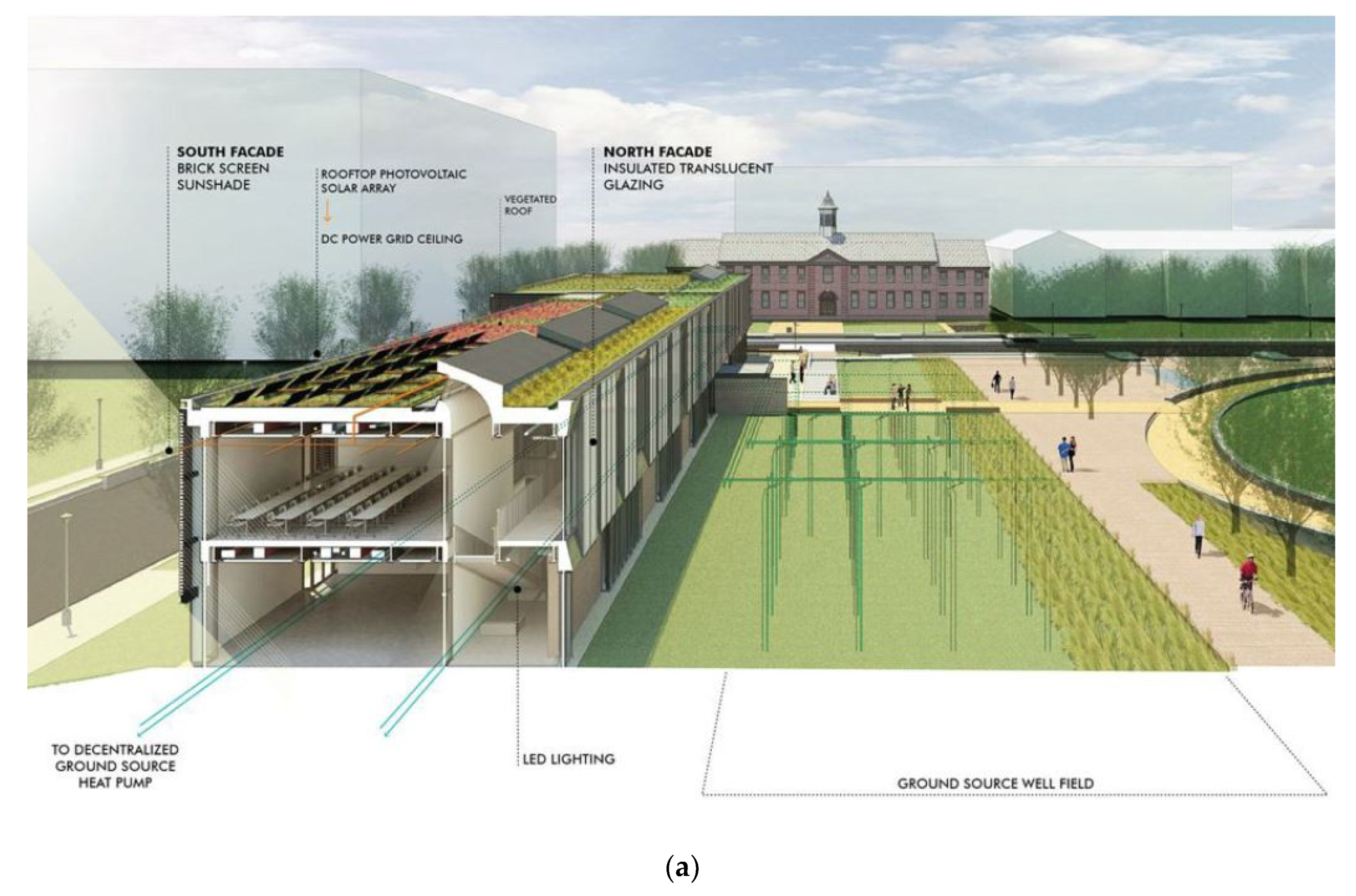
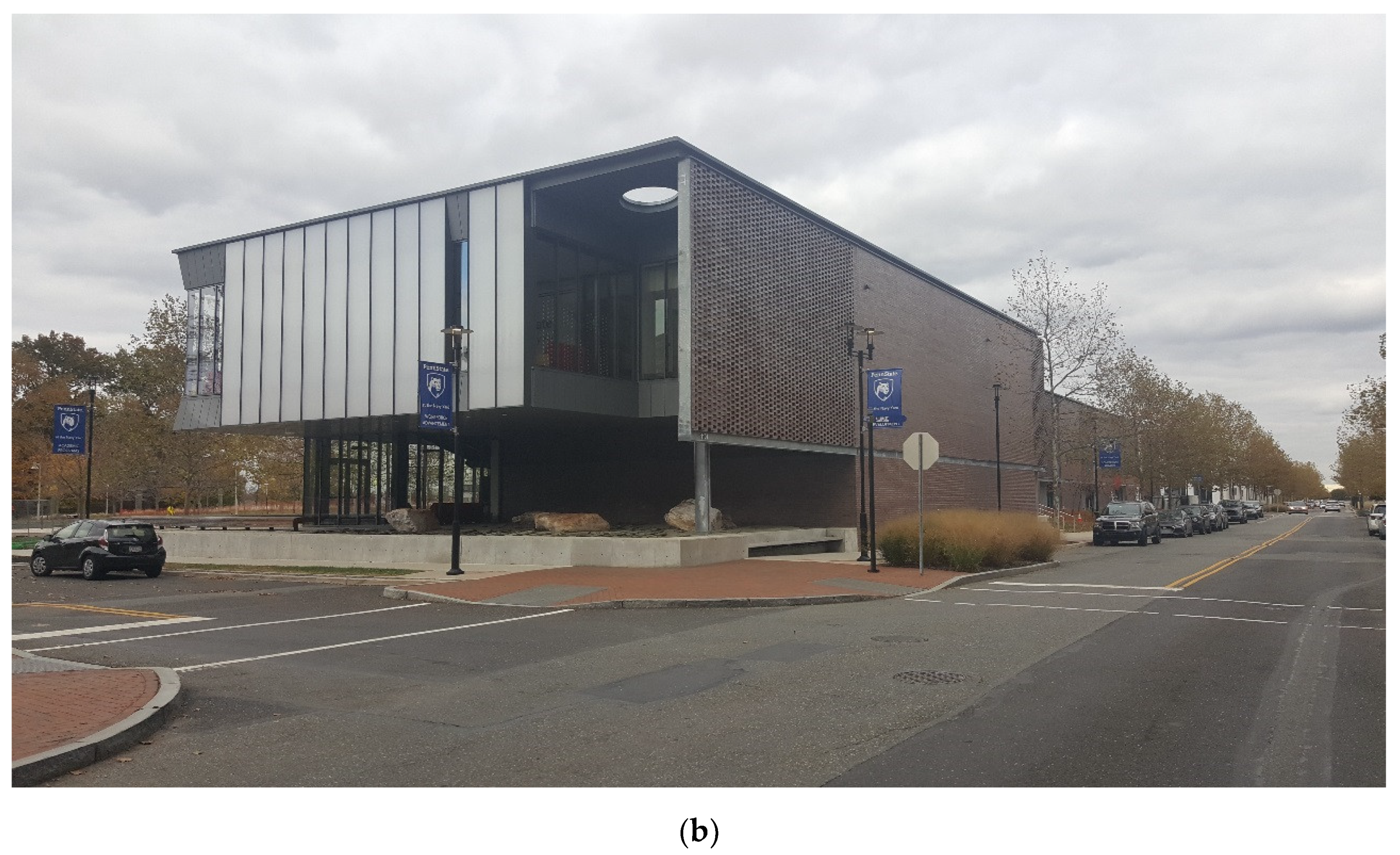
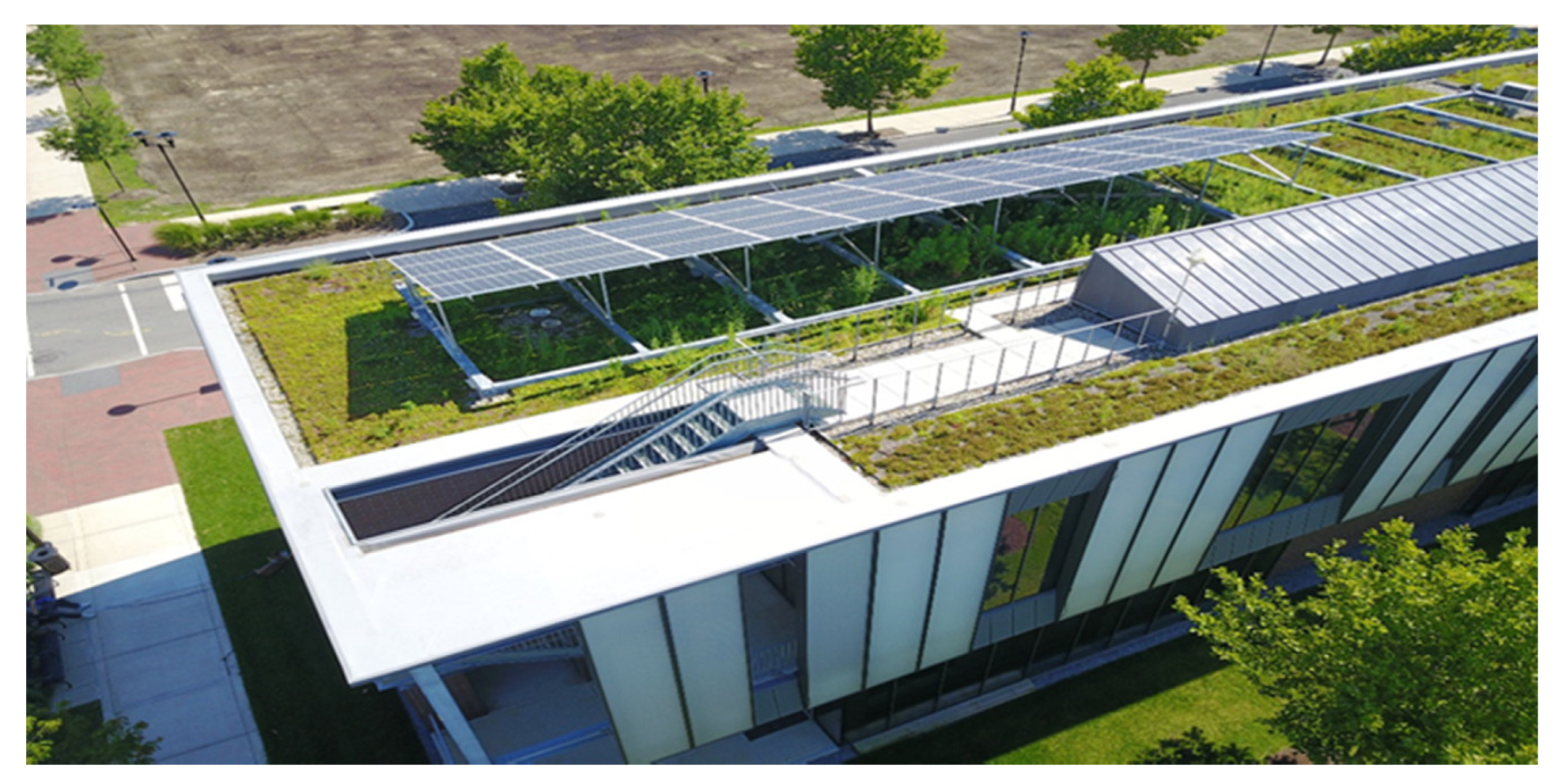
3.1. Microgrid Host Site-Building 7R

Building 7R, a part of Penn State at the Navy Yard Campus, is located in the Philadelphia Navy Yard and was constructed as an energy-efficient building [43,44].The location is significant as The Navy Yard has nearly complete autonomy in managing electricity distribution within its boundaries including allowing and enabling third party management of reverse power flow from buildings including 7R back to the grid. In addition to serving its academic purpose, the building is designed to function as a living laboratory for advanced building energy efficiency and sustainability measures (Figure 5). The building was built in 2015 with a gross floor area of 2341 m2 (25,200 ft2). Key energy efficiency and sustainability measures implemented include geothermal heat pump system, green roof, demand control ventilation, and energy recovery ventilation, and advanced integrated daylighting strategies. The building-to-grid integration capabilities including the inverter and solar PV, were added during and after the building construction in relation to another project from the U.S. Department of Energy [45]. Subsequently, microgrid components were installed as part of a project funded by the Pennsylvania State Department of Environmental Protection (DEP) [46]. The focus of this paper is the development of the microgrid control platform for building 7R which is tasked with dictating control decisions to installed microgrid components, including a 65 kW natural gas-fired microturbine, a 10 kW Solar Photovoltaic (PV) arrays, lithium-ion and lead-acid energy storage systems, a microcontroller, and the building automation system. The reminder of this section is devoted to briefly describing the building followed by the components of its distributed energy resources listed earlier.
The building is composed of offices, classrooms, and other educational spaces and an auditorium with a diversity of heating, cooling, and electric loads. While the office spaces have consistent baseline loads, the educational spaces including, lobby (maximum occupancy 50 people), classrooms (maximum occupancy 100 people), and an auditorium (maximum occupancy 165 people), have transient loads. To meet the heating and cooling loads in this two-story building, the building has a water to water source heat pump (WSHP) entailing 32 wells with 350 feet deep (Figure 5b). The building utilizes a number of daylighting strategies and is powered by LED lights.

3.2. Distributed Energy Resources (DERs)
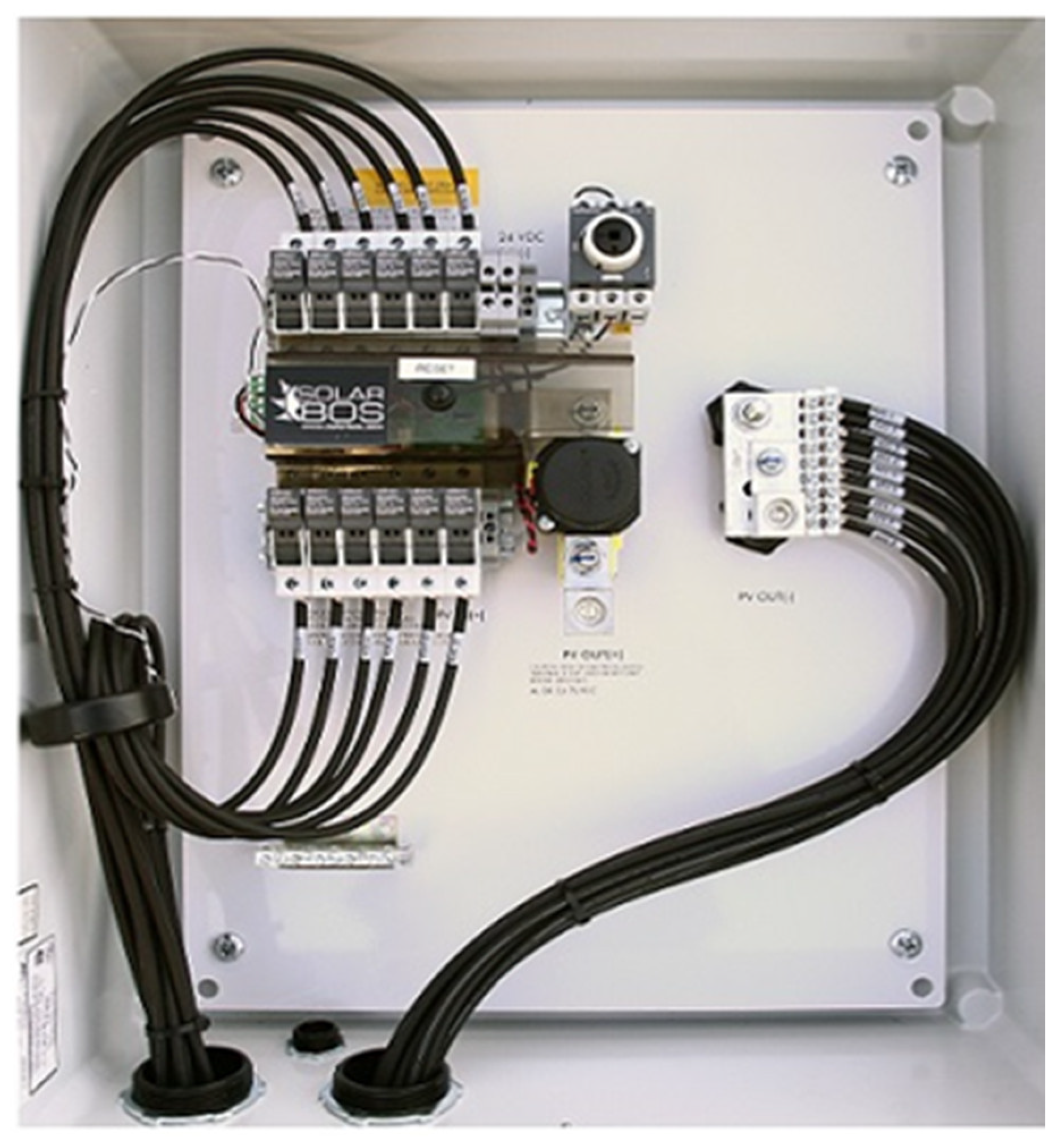
The distributed energy resources (DERs) consisted of physical assets (Solar PV, energy storage, and microturbine) in conjunction with virtual assets (building demand management) assist the electrical grid in serving building loads when the building is connected to the grid and are the sole provider to critical loads when it is not. As we gradually reduce our reliance on centralized bulk generation, DERs are changing the way power is generated and distributed in the electric grid. Moreover, they provide resiliency and/or rely on more sustainable energy sources and defer capital investment in demand-constrained areas. In the following, DERs and associated technologies utilized in building 7R are discussed.

3.2.1. Solar PV

The building green roof hosts a 10 kW solar photovoltaic (PV) array, as shown in Figure 6. The array will produce 10.1 kW of power at its peak. The average electricity output is 13,000 kWh/yr. During the winter months, there is an 8–13% loss in generation due to shading and lack of sunlight. The shading losses during spring and summer are negligible because there is more than enough sunlight to generate electricity. The solar array can operate in the temperature range of −15 °C to 40 °C with efficiency around 15.7% [48].
The array was installed at a 15° tilt angle is and 174.3° solar azimuth. It is structured into 40 mounted modules with 60 monocrystalline silicon cells per panel. There are 4 rows of 10 panels each on top of 7R. The whole system is wired as 3 strings of 13 modules, with one unused module to build up the proper voltage to match the inverter operating range. In order to combine the output of multiple strings of PV into one main feed that is fed to the inverter, a combiner box [49] by SOLARBOS (SolarBOS, Grand Rapids, MI, USA) was used, as shown in Figure 7. The combiner box is installed between the solar array and the inverter, and in addition to combining the output of the three strings, provides overcurrent and overvoltage protection to protect the inverter as well as the means to quickly shut off the power on one section of the PV circuit (DC disconnect).

3.2.2. Energy Storage

Since the microgrid utilizes intermittent renewable sources of generation or other distributed generation sources that can be operated for a limited number of hours annually, an energy storage system (ESS) should be deployed to enable the microgrid to function while in different modes of operation when it is in connected to the grid and when it is islanded. ESS enables matching the load with generation and is a requirement where intermittent resources are utilized, especially since peak generation and peak load may occur at different times. Additionally, an ESS can act as a buffer to absorb power from renewable sources while the microturbine operates at its optimum operating efficiency. Finally, ESS is essential for a smooth transition from/to grid-connected to/from islanded operation.
A battery energy storage system (BESS) utilizes different electrochemical batteries arranged in series and parallel to generate desired voltage and current respectively and a dedicated control system for each chemistry to manage its state of charge (SOC) and physical and operational variables including temperature, rate of charge, and rates of discharge. In addition, the BESS should be able to communicate with a charge controller (normally a part of the inverter) to enforce the proper values for those variables (especially rate of charge and rates of discharge and changing them when it approaches high or low SOC). Different applications (i.e., power vs. energy) require different chemistries based on their operational parameters.
In the building hybrid microgrid implementation, two different battery chemistries (lead-acid and lithium-ion for energy and power applications respectively) are deployed. The lead-acid BESS utilizes Enersys Nexsys 12NXS186 (Enersys, Reading, PA, USA) batteries [50] shown in Figure 8a and is a valve-regulated lead-acid battery (VRLA). It is of the absorbed glass mat (AGM) type and as a result, has enhanced cyclic capability (up to 1200 cycles at 60% Depth of Discharge) compared to conventional (gel or flooded) lead-acid batteries. The bank has 45 batteries in series and has the capacity to supply up to 17 kW of power and can store 60 kWh of energy and 186 Ah of electric charge. The function of this unit is to safely store excess energy generated by the solar array or microturbine, providing power when the system calls for it. However, this type of battery chemistry cannot respond rapidly enough to changes in solar PV output to handle some common conditions, such as when clouds abruptly shade the PV array.
The lithium-ion BESS, manufactured by ALLCell, shown in Figure 8b, utilizes LG 18650 MH1 (LG, Seoul, South Korea) cells based on a Lithium Metal Oxide proprietary chemistry [51]. The lithium-ion BESS is nominally discharged three times as fast compared to the lead-acid BESS. A summary of cell and pack specifications is provided in [52]. The BESS can respond very rapidly when dispatched by the inverter with up to 50 kW of power with its 39 kWh energy capacity. The BESS can also perform frequency regulation when called upon by a curtailment service provider by injecting power to the grid when frequency drops and absorbing it when it rises, a service with monetary compensation by the regional transmission organization (RTO).

3.2.3. Multiport Inverter
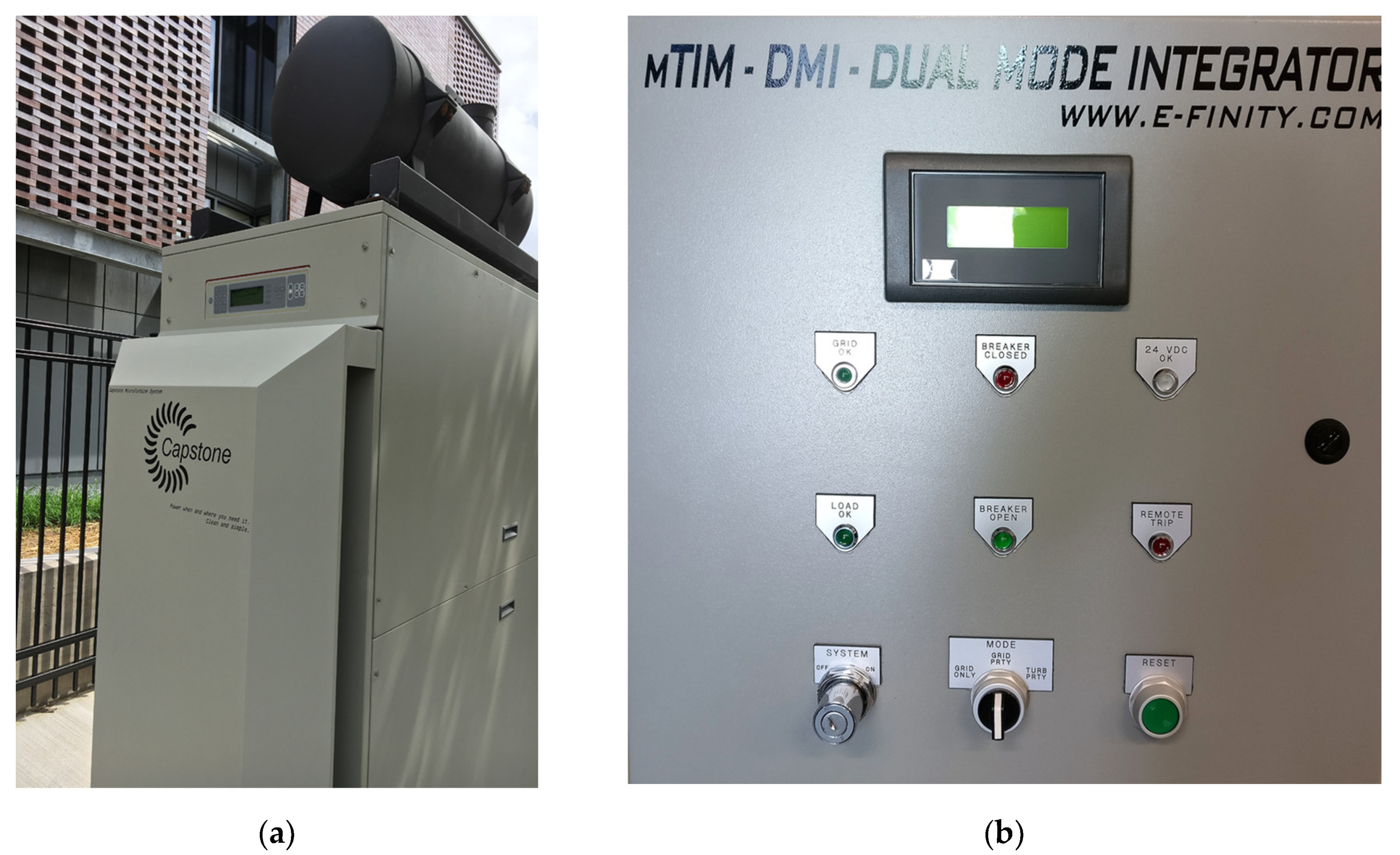
The 50 kW inverter [53] enables DC-coupling of solar and battery energy storage as opposed to AC-coupling the DERs through separate inverters. The multiport inverter supports three DC ports and two AC ports. In this application, the first DC port is connected to the solar PV array, the second DC port is connected to the lithium-ion battery system (main battery), and the third DC port is connected to the lead-acid battery system. The first AC port is the grid connection, and the second AC port is the load connection. Energy can flow from DC to DC and AC side, from DC to DC side only (PV charging either battery) or from AC side (grid) to AC load and DC side (batteries). Finally, the AC grid and any combination of DC ports can supply power to the load. The inverter operation will be covered in more detail when the microgrid modes of operation are discussed in Section 4.

3.2.4. Microturbine

Combined Heat and Power (CHP)—simultaneous production of electricity and heat from a single fuel source—as a distributed energy resource can enhance reliability and resiliency in buildings since it has proved its value as an alternative source of power and thermal energy (heating and cooling) during extreme weather emergencies [13]. CHP has many benefits, including a substantial increase in energy efficiency compared to separate power and heat generation. To help realize these benefits and advance its adoption, in the U.S., regional CHP Technical Assistance Partnerships (CHP-TAP) have been funded to provide expert advice and to determine the suitability and economic impact of CHP based on site conditions for different applications including building-scale microgrids [13,14].
Microturbines are relatively small combustion turbines that can use gaseous or liquid fuels and in smaller sizes (30 to 330 kilowatts (kW)) have emerged as a CHP option (with lower emissions compared to other technologies) since the 1990s [54]. This size range has made them a feasible option as a distributed energy resource in the building scale.
A Capstone 65 kW combined heat and power (CHP) microturbine (c65) (Capstone Turbine, Los Angeles, CA, USA) [55,56] was selected as the electric generator deployed outside building 7R, as shown in Figure 9a. The microturbine is fueled by natural gas and is limited to 2000 hours per year of operation per its permit. The 7R microturbine is a dual-mode DER, it can run by itself (stand-alone) or can be connected to the grid. In order to enable the microturbine to transition automatically from grid-connect to stand alone mode of operation during an unplanned outage, a dual-mode integrator (DMI) (E-Finity Distributed Generation, Wayne, PA, USA) shown in Figure 9b has been utilized [57]. When the DMI senses power outage, it disconnects the microturbine and its critical loads from the electric grid. After a delay, the microturbine is powered up and supplies stand-alone power. Finally, when the power comes back on, the DMI operates the microturbine in grid-connect mode after a delay. The default mode of operation for the DMI is operating the microturbine parallel to the grid. The details of mode transitions when the solar PV inverter is also involved and controlled under the microgrid controller is covered in Section 4.
In a potential future system extension (contingent upon availability of funding), the waste heat of the microturbine can be utilized in a combined heat and power (CHP) application which would significantly increase the efficiency of the microturbine from the current 30% to total system efficiency of between 60% and 80% [56]. This can be accomplished by installing an integrated heat recovery system that can provide considerable thermal energy by capturing waste heat generated by the combustion of natural gas. Since this is an all-electric building, one possible use of the waste heat is for space heating of neighboring buildings in the Navy Yard campus through a district hot water system. Another possible use of the waste heat could be in supplying the heat to air-cooled absorption chillers for space cooling. Due to the proximity of this building to other buildings with different heating and cooling load requirements, all of these solutions are feasible, and future work can assess different design scenarios to utilize the microturbine waste heat.

4. Implementing Control for a Building-Scale Microgrid

There are several examples of microgrid control implementations in the literature [16,17,58,59,60,61,62], to name a few. All of these implementations rely on communication networks and protocols that are well-established in electrical distribution systems, covered in Section 4. In contrast, in order to implement behind-the-meter control in a building, a dedicated communication network should be designed and implemented. In the following, the communication infrastructure, the components and their function, information collected and sent to the controller (inputs), and controller commands (outputs) using this communication infrastructure and their functional significance in microgrid control are discussed.

4.1. Microgrid Control Components, Their Function, and Interconnections

The communication infrastructure for the microgrid control platform is depicted in Figure 10. This platform was installed by the project contractor [63] by running category 6 Ethernet cable enclosed in metal conduits connecting all indoor and outdoor components which lie on different networks separated from each other physically or virtually, including a virtual private network for microturbine remote monitoring and maintenance. Some components are powered through a Power Over Network (POE) switch, as noted. The protocols used to connect the component and the microgrid controller are listed below, next to each component. Since this project involves controlling building loads through collecting information from the building automation system (BAS), a method had to be devised to enable the BAS to communicate with DER controllers and the microgrid controller. Since BACnet is a communication protocol developed by the American Society of Heating, Refrigerating and Air-Conditioning Engineers (ASHRAE) for the BAS to interact with building systems, a BACnet to Modbus (Modicon, North Andover, MA, USA) gateway is utilized, so BACnet [64] and Modbus signals can be translated into each other.
It can be observed that compared to the larger scale microgrids implemented in electric distribution network with a dedicated communication infrastructure and established protocols implemented in industrial-grade components [16,58,60] to name a few, a building-scale microgrid has to rely on off-the-shelf commercial components and standards from different domains which necessitates more complex maintenance. The control components for this building-scale microgrid are listed below:
  • Energy IQ Controller (Energy IQ, Boca Raton, FL, USA; The Microgrid Controller): Centralized SCADA site controller. A programmable Industrial PC [65] running an open driver-based and JAVA-based supervisory platform used in building automation systems (Niagara N4) [66] providing integration to various Modbus-based DER components, listed below.
  • Dynapower Inverter Power Control System (PCS;South Burlington, VT, USA) [53]: The Modbus-based primary controller for the Dynapower inverter. The PCS is in charge of switching between its grid-connected and islanded modes of operation.
  • Microturbine Interface Module (mTIM; E-Finity, Wayne, PA, USA) [67]: The Modbus-based primary controller for the Capstone microturbine. This component coordinates with the microturbine dual mode integrator (DMI) in charge of switching between its grid-connected and islanded modes of operation.
  • elithion AllCell Battery Management System (BMS; elition, Boulder, CO, USA) [51]: The CAN bus-based primary controller for the AllCell lithium-ion battery energy storage system.
  • Cellwatch PC Battery Management System (BMS; Cellwatch, Raleigh, NC, USA) [52]: The Modbus-based primary controller for the lead-acid battery energy storage system.
  • JACE controller (Tridium, Richmond, VA, USA) [66]: The BACnet-based controller/server for the Building Automation System (BAS).
In addition to the above main components in the control hierarchy (microgrid controller—secondary and tertiary level) and DER (primary controllers) that interact with the building automation system, there are a number of other network components as depicted in Figure 10 that collect information useful for microgrid control which will be addressed in the next subsection. These components are scheduled to be configured in the next phase of the project, including the General Electric (GE) Microgrid Controller—an islanding controller—integrated into this platform by GE, a project partner.

4.2. Data and Command Flow between Controller and Components

The data and command flow of a typical microgrid is depicted in Figure 11. It can be observed that data is collected from, and control signals are issued to all three layers of the control hierarchy covered in Section 2 (Figure 2): microgrid optimizer, dispatch, and CERTS autonomous layer. These data and commands are encoded into communication signals in different protocols and communicated between the controller and different components in Figure 10.
In other words, the command the data and flows in Figure 11 can be mapped to components in Figure 10, as shown with the following examples. Each mapping corresponds to a programming scenario for the controller. (More details on that will be provided later in this paper.) The one to the last horizontal arrow in the lower-left section of Figure 11 corresponds to the meteorological station that includes a pyranometer that measures solar irradiation and sky camera (a fisheye camera with 180-degree view) that reports on cloud covering sending data to the controller that it can compile into information on the availability of the solar resource. On the other hand, the bottom-left data flow in Figure 11 corresponds to the Building Automation System sending information on building loads to the controller. (The controller utilizes the discovery function of BACnet to configure data points available in the Building Automation System.) All modules including the “Unit Commitment Dispatch and Load Shed” module in Figure 11, are implemented in a Java programming block based on the Niagara platform installed on the controller. Based on these on other data flows, the controller’s dispatch module issues commands containing set points for real and reactive power for the distributed energy resources (“P & Q Dispatch” Arrow in Figure 11).
As other examples of the data flow reported to the microgrid controller, the other blocks in the left portion of Figure 11 report the voltage (V), current (I), both AC and DC (in the case of the inverters), real (P) and reactive (Q) power of the DERs and in case of battery energy storage, the state of charge (SoC) as well, to the microgrid controller. In the current state of the project, all these pieces of information are obtained by the controller addressing the Modbus registers of the DERs. In the future, additional metering will be installed. Another important example is the “Historical Database” module, implemented in the platform by utilizing a PI server (OSIsoft, San Leandro, CA, USA; https://www.osisoft.com).
Now that the layout, components, and data and command flow of the control platform are explained, we will discuss how the platform is utilized to implement the three layers of the control hierarchy (Figure 2), from the bottom to the top.

4.3. Implementation of Lowest Layer: CERTS Autonomous Layer

We recall from Section 2 that this layer is tasked with power-sharing control of multiple DERs and functions related to the transition between grid-connected and islanded modes of operation, including switches, disconnect devices, and protection and have cycle-scale timing (10–100 milliseconds). Although these functions take place autonomously during unplanned islanding and without controller intervention, the controller collects status information from transfer switches and breakers operating at this level and has the ability to command them during a planned islanding event. There are three devices in this layer, as listed below.
The first device in this layer is a triple-pole motor-operated breaker (3-phase, 125A; Eaton, Beachwood, OH, USA) [68], acting as the islanding contactor for the building-scale microgrid. In the event of grid power loss, the breaker opens, commands the microturbine to power off (if running through) the DMI and mTIM modules discussed earlier and disconnects the microturbine from the grid. It will serve the critical building loads through the ATS, below.
The second device in this layer is an automatic transfer switch (ATS; Eaton, Beachwood, OH, USA) [69] that, in the event of an outage, switches from the grid (primary source) to the microturbine (backup source). The load side of the ATS is wired to the first AC port of the inverter. The second AC port is connected to the critical load panel.
The third device in this layer is the SEL-547 directional power relay (Schweitzer Engineering Laboratories, Pullman, WA, USA) to avoid reverse power [70]. The reverse power protection is used to protect the microturbine, since if a generator takes in power, it will act as a synchronous motor which could lead to turbine blade failure.
Testing the islanded modes and transition to/from them is pending the building owner’s (Penn State) Office of Physical Plant approval, and as the result, at the time of this writing, the two tests conducted on the system in its current state were in the grid-connected modes of operation.
It should be noted that the tests conducted in Section 5 are in grid-connected modes and do not involve operating the two DERs in a CERTS configuration (Section 2.2, not to be confused with the name of the lowest layer in the control hierarchy) where they power-share serving the loads through droop control, as discussed earlier. Either DER (microturbine or Solar PV inverter) can serve all the critical loads in building 7R, and in this case, there is no need to program the DERs to operate in the CERTS configuration.

4.4. Implementation of the Dispatch and Optimizer Layers

Currently, only the dispatch layer is programmed in the controller. In this mode, power dispatch commands can be issued to the DERs so they can be operated per manufacturer’s specifications. However, the decision to select a controller [65] that utilizes an open driver-based system [66] where it can readily communicate with the building automation system (BAS) compared to a proprietary system, such as [62], enables ongoing development in the context of university research as additional funding is secured. Additionally, programming for demand curtailment scenarios can also involve changing building set points at peak demand times and reusing programming blocks between the microgrid controller and the BAS.

4.4.1. Control of Microgrid Operational Modes

In the following, grid-connected and islanded modes of operation will be discussed along with the unique resiliency or economic goal the microgrid should fulfill in each scenario based on the grid, DER, and load situation. It should be noted that scenarios implemented in the optimizer layer have not been tested (please see the Future Directions Section), and only those implemented at the dispatch layer have been tested, as documented later in this paper. For the grid-connected modes, the utility or curtailment service provider (Tangent, Figure 10) has the ability to coordinate the execution of the mode with the controller.
• Grid-connected Modes
In all grid-connected modes, the dispatched DERs will operate in grid-following mode (PQ) since the grid ensures stable voltage and frequency values. Accordingly, the controller assigns real and reactive power values to each dispatched DER. The internal controller of each DER ensures these power values are maintained. In each of the following modes, the decision to dispatch the microturbine, solar PV inverter, or both and the assigned power values to each is dependent upon the mode, solar radiation, battery state of charge, grid conditions (i.e., peak demand times), and building demand during each calculation horizon. In the next phase of implementation, the microgrid controller will be programmed to solve and accordingly assign power set points for each calculation horizon. The modes followed by a brief description of each are listed below:
○ Base loading
For the duration of this mode, the controller assigns fixed power setpoints for the microturbine and the inverter. The remaining power for the building is provided by the electric utility.
○ Load following
In this mode, the controller in successive time intervals alters set points assigned to the microturbine and inverter up to an assigned maximum value to meet varying building demand. As the DERs are ramped up, the electric utility supplies the difference between demand and total generation.
○ Peak shaving and electric sales
When demand is above a certain value for certain days, the controller reduces the building demand by a combination of the following: dispatching the DERs, commanding the building automation to apply its pre-programmed demand reduction strategy and to shed loads in the following order: lighting reduction [71], unloading of pumps and fans, and changes in HVAC set points. It should be noted that if due to high demand, grid prices are higher than the microgrid’s cost to produce power, the controller can increase the set points for the microturbine and inverter, so excess electricity is generated and sold back to the grid.
○ Frequency regulation
In this mode, by dynamically changing the set point for the inverter such that power from the batteries is injected into or absorbed from the grid, the controller can increase/reduce the frequency and effectively act as fast-acting frequency regulator and generate revenue for the system.
• Islanded Modes
When grid-wide power failures occur, they are sensed by both the Panel TP and ATS, and as a result, the Panel TP islands off the grid, and the ATS switches to the critical load panel.
○ Inverter as grid-forming source, setting U (output voltage) and F (frequency): UF Mode, microturbine off.
In this mode, the primary controller of the inverter controls voltage and frequency.
○ Microturbine as grid-forming source (UF Mode), inverter as grid-following source (PQ Mode), setting P (real power) and Q (reactive power).
In this mode, the microturbine primary controller controls voltage and frequency, and the inverter executes a dispatch command from the microgrid controller, and its primary controller ensures real and reactive power levels are maintained.

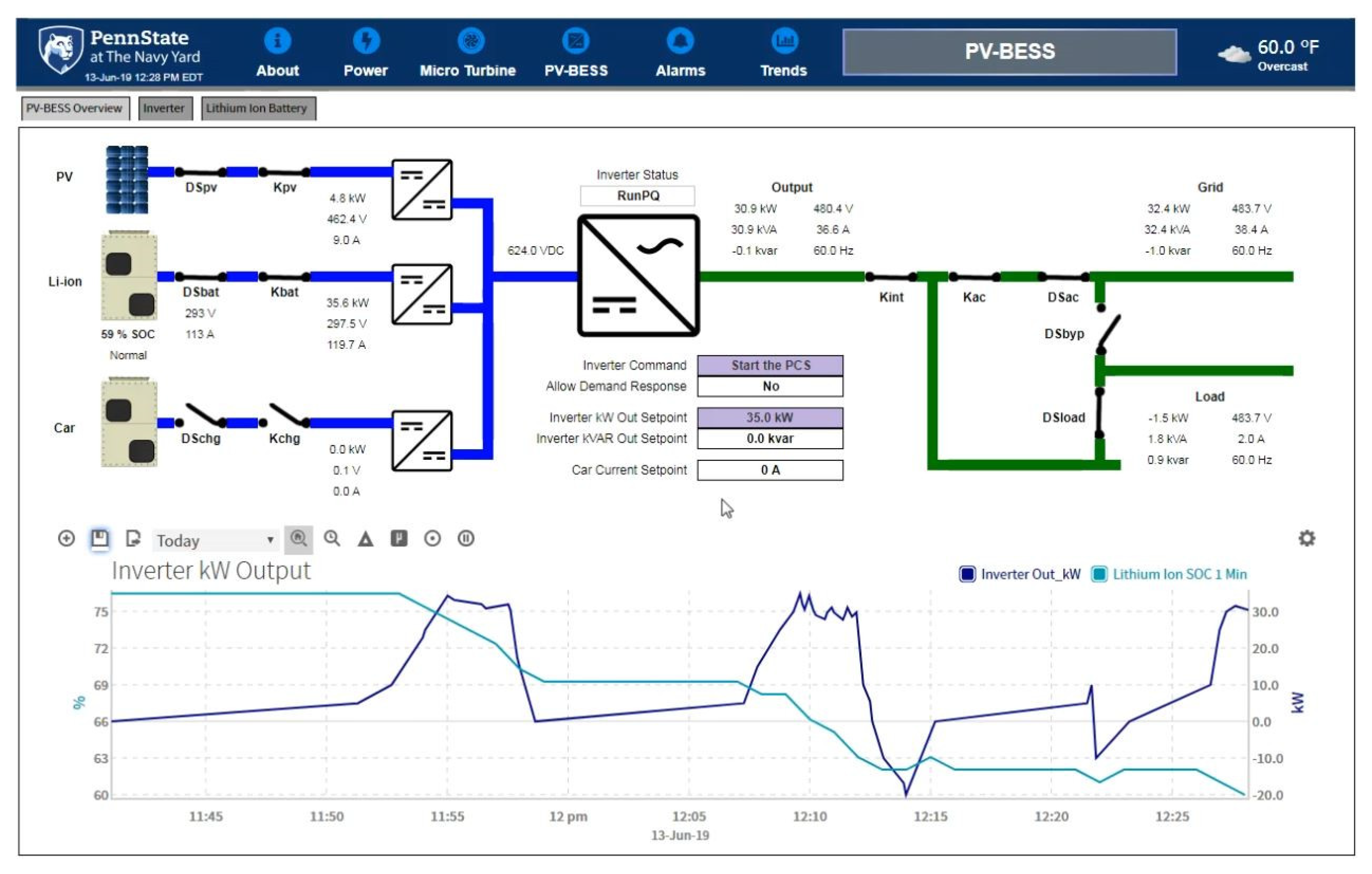
4.4.2. Inverter Operating Modes

The microgrid controller commands bidirectional current flow and consequently power on each DC port in order to maintain an optimum state of charge and can command the inverter to transition between grid-connected (PQ) mode where real and reactive power setpoints are assigned to the inverter and standalone (UF) mode road inverter maintains output voltage (480 V 3 Phase) and frequency (60 Hz). The DC-coupled setup avoids unnecessary conversion losses associated with AC-coupled systems. In addition, it enables fast output response on load step-up/down in both grid-connected and standalone modes. In addition to serving as the primary controller for all distributed energy resources connected to its three ports, the inverter’s domain controller handles all the communication protocols and directs commands to the appropriate embedded systems as requested by the end-user.
The main operational limitation of the inverter that the microgrid controller should be closely monitoring the DC bus voltage. The voltage should not drop below 450 V, which would cause the inverter to trip under battery under-voltage. On the other hand, if a battery reaches its high voltage limit (697 V), the controller should stop the PV DC/DC converter for a while (until the main battery is discharged halfway) and power to the grid/load is supplied by the main battery only.
In grid-connected (PQ) mode, the power from/to the battery is defined by subtracting the power delivered by solar PV from the absolute value of the +/− kW set point signal issued by the microgrid controller. During standalone (PV) operation of the inverter, if the main battery is the only source and the other two DC ports are disconnected, the output power is determined by the load demand (subject to a limit set by microgrid controller) while voltage and frequency are fixed. The inverter can support this mode if the battery voltage does not drop below 450 V. If the main battery and solar PV are present in standalone (PV) operation of the inverter, the power in excess of the load demand charges the battery. Once the batteries charge up to limit, the microgrid controller disables the solar PV DC/DC converter until the main battery is charged halfway.

4.4.3. Microturbine Operating Modes

The Capstone C65 microturbine operates in one of the following two operational states [57]: Stand Alone (SA) and Grid Connect (GC). In normal GC operation, the microturbine contactor is closed, and the microturbine is capable of exporting power in excess of building loads to the grid. When a disturbance is detected on the utility grid, voltage and current sensing in the microturbine will cause the internal contactor to open, and the microturbine will go through a shutdown procedure. When the conditions have been met to allow reconnection to the grid, the output contactor will automatically close, and the microturbine will be restarted.
Transition to the SA operational mode takes place in less than 7 seconds after the SA enable signal is issued by the microturbine control system. External control actions, including those initiated by the microgrid control system, should proceed with this action. The transition back to the GC mode, on the other hand, involves a 0–30 minutes adjustable wait timer during which load voltage is maintained. Afterward, the microturbine enters the Hot Standby operational mode and remains in this mode until it is ensured the utility voltage remains within the protective relay setting limits for the reconnect time delay, adjustable between 5 (per IEEE 1547.1 and UL 1741 standards) and 30 minutes—afterward it switches to the GC mode.

4.5. Testing Hierarchical Control

The platform was used to test hierarchical control at the dispatch layer in the grid-connected mode of the controller, by assigning power set points to the DERs and observing the DERs operation. The first test was conducted on the inverter, and the second test was conducted on the microturbine.

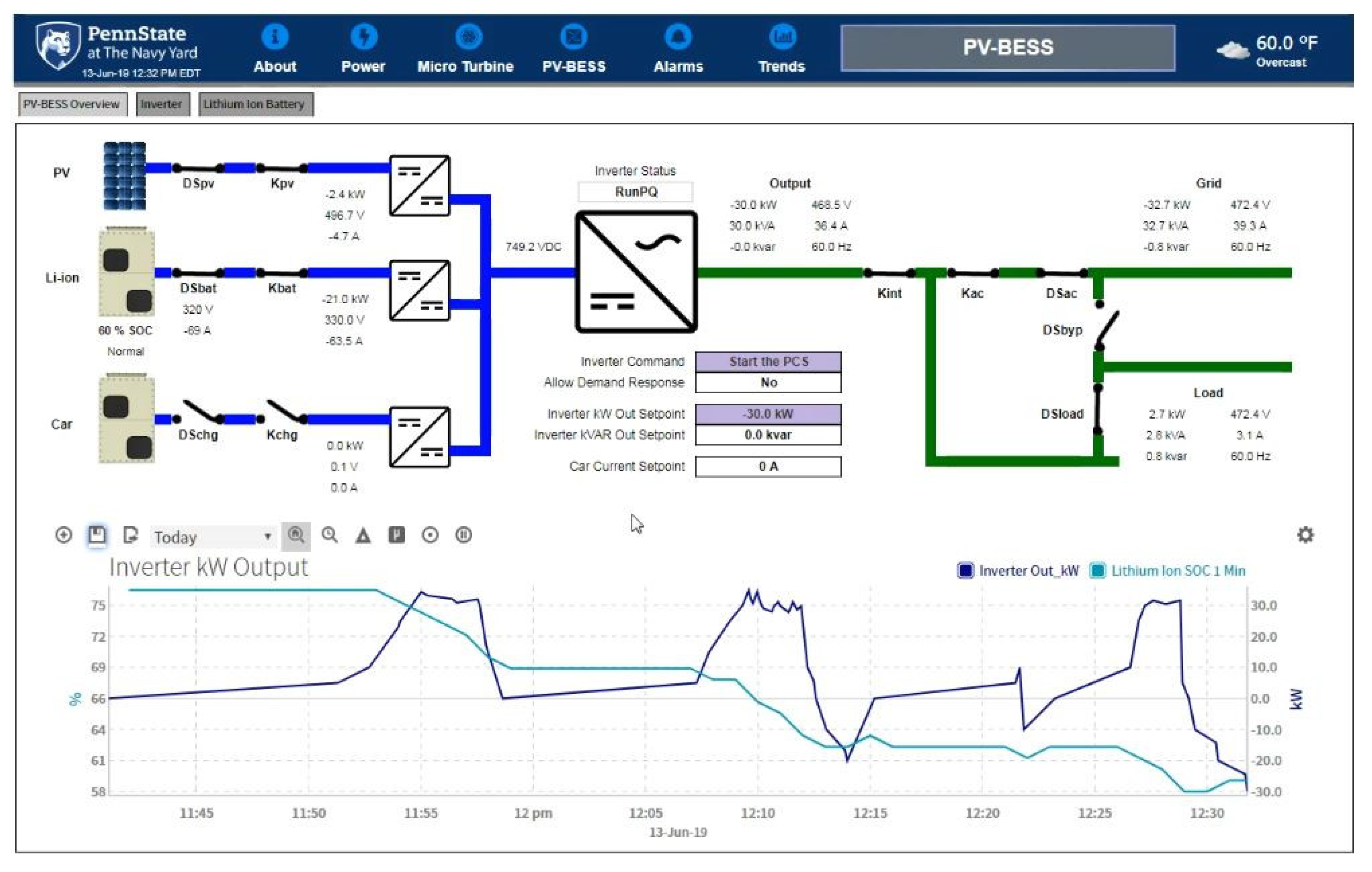
4.5.1. Experiment 1: Dispatch Layer (Solar PV + Storage Inverter)

The controller operates the inverter in PQ mode (grid-connected). The set point for real power (P) is changed, and the inverter reacts based on new P values. The graphical user interface (GUI) from the microgrid controller, Energy IQ, confirms the dispatch layer was successful. Figure 12 demonstrates the grid-connected base-loading mode where the controller commands the inverter with the positive P value (inverter exporting power to the grid) as a set point. As can be observed in Figure 12, both the discharging battery as solar output contribute to providing the power set point (P value).
Figure 13 demonstrates the grid-connected base loading mode where the controller commands the inverter with the negative P value (inverter importing power to the grid) as a set point. As can be observed in Figure 13, both the grid and solar contribute to charging the battery.

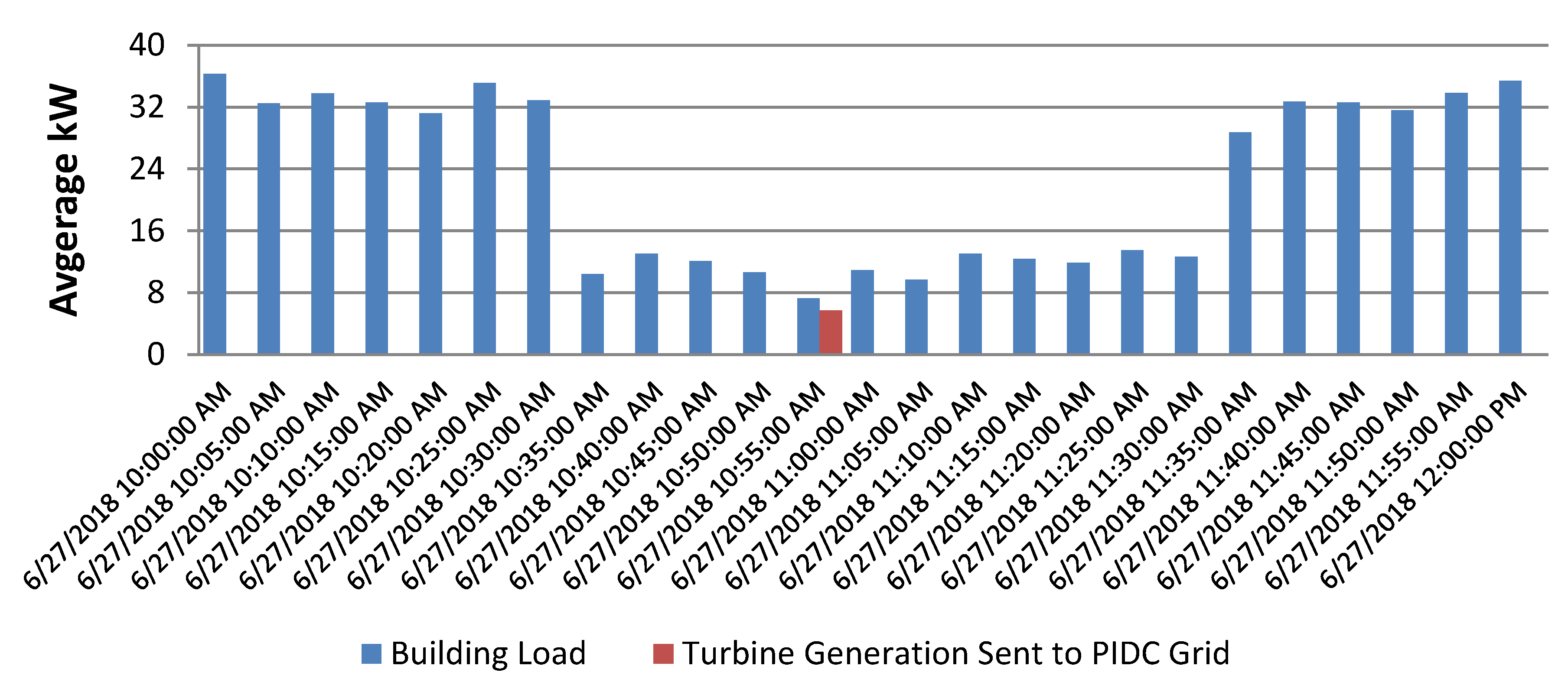
4.5.2. Experiment 2: Dispatch Layer (Microturbine)

In Figure 14, interval data from the main building meter shows the microturbine was active between 10:35 AM and 11:30 AM during the test day, where it was operated with the P value of 20 kW. As the result of its operation, the average power imported from grid dropped from 32.7 kW to 12.8 kW and at 10:55 AM, when it was ramped up to 65 KW for a short period of time, this new P value resulted in an average (calculated over 5-min intervals) of 6 kW net power exported to the grid at 10:55 AM.

5. Simulation of Optimized Dispatch for Demand Charge Reduction

Before discussing the HOMER Grid simulation, the power limits the software observes for charging and discharging the battery and is applied to the simulation is explained.

5.1. Maximum Battery Discharge and Charge Power

The maximum amount of power that the storage bank can discharge (charge) over a specific length of time can be calculated based on the Kinetic Storage model [72] illustrated in Figure 15.
Based on the model, the following equations can be derived:
d Q 1 d t = P ( t ) + k ( h 2 h 1 ) = P ( t ) + k ( Q 2 1 c Q 1 c )
d Q 2 d t = k ( h 2 h 1 ) = k ( Q 2 1 c Q 1 c )
Q 1 is the available energy [kWh] in the Storage Component at the beginning of the time step, Q 2 is the total amount of energy [kWh] in the Storage Component at the beginning of the time step (bound energy), c is the storage capacity ratio [unitless], k is the storage rate constant [ h 1 ], h 1 is the height of available charge well, and h 2 is the height of bound charge well. The initial conditions are:
Q 1 ( 0 ) = c Q m a x & Q 2 ( 0 ) = ( 1 c ) Q m a x
where Q m a x is the total capacity [kWh] of the storage bank. Solving the above differential equations yields the following equation for maximum discharge power:
P b a t t ,   d m a x , k b m = k c Q m a x + k Q 1 e k Δ t + Q k c ( 1 e k Δ t ) 1 e k Δ t + c ( k Δ t 1 + e k Δ t )
Through a similar approach, we arrive at the following equation for maximum charge power:
P b a t t , c m a x ,   k b m = k Q 1 e k Δ t + Q k c ( 1 e k Δ t ) 1 e k Δ t + c ( k Δ t 1 + e k Δ t )
where Δ t is the length of the time step [h].

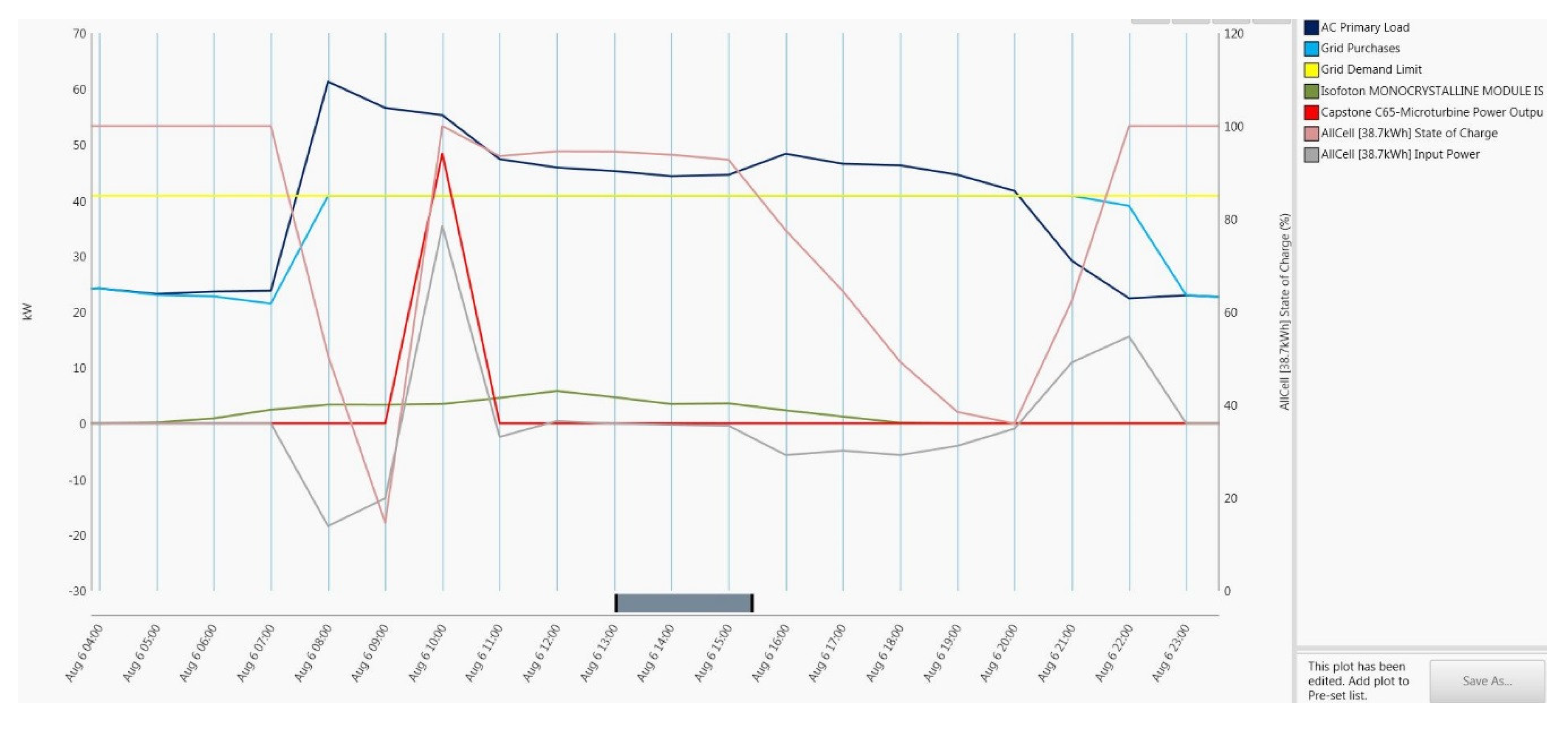
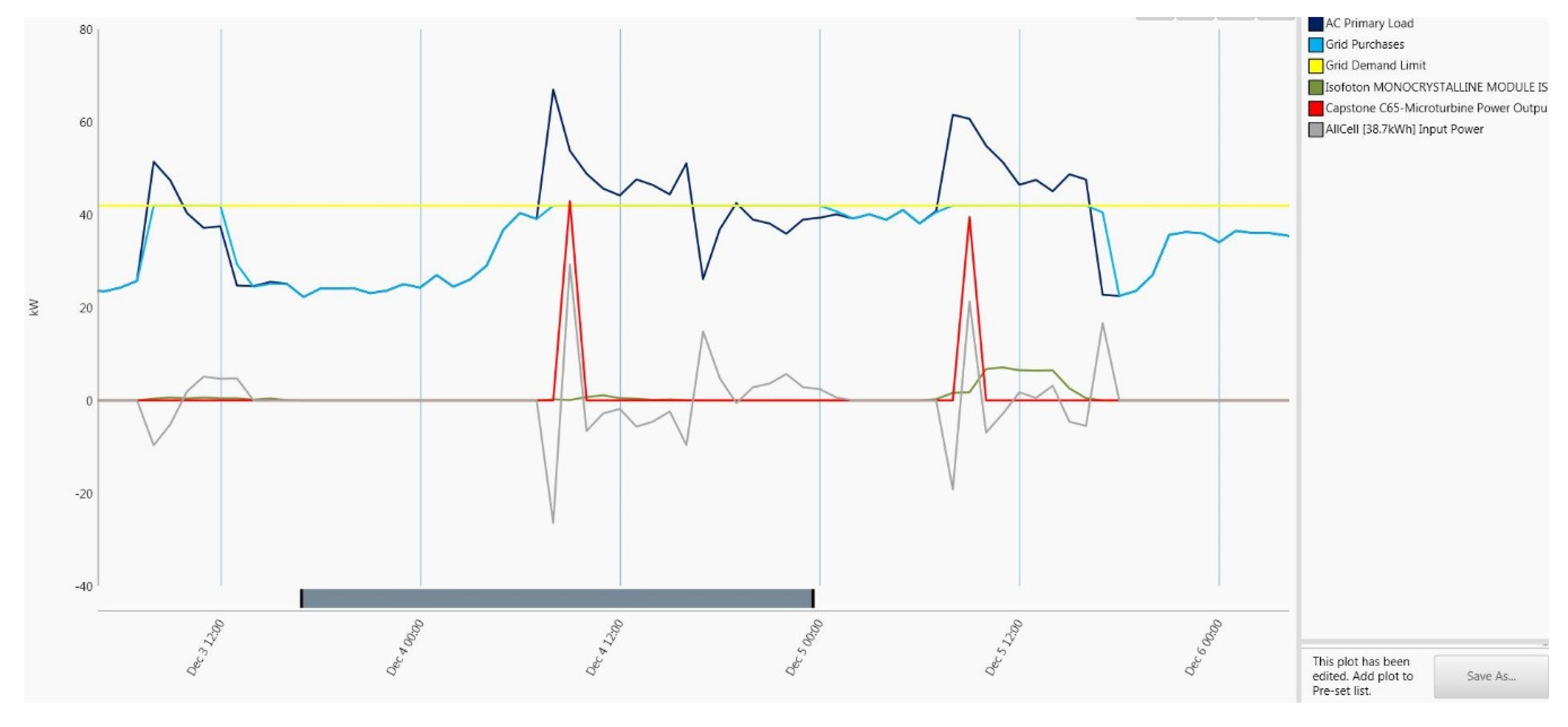
5.2. HOMER Grid Simulation

The main focus in this HOMER Grid simulation [73,74,75] is optimizing distributed energy resource dispatch with the main objective of demand cost reduction. The primary advantage of Homer Grid is its integration with the Genability tariff database [76] to efficiently model the economic effect of various control strategies for distributed energy resources. HOMER Grid aims to limit the monthly demand charges and therefore reduces the total operational cost.
HOMER simulates optimal control strategies with the goal of the most economic DER (i.e., solar, batteries, and microturbine CHP) dispatch to avoid significant demand charges. The CHP can operate only if it is loaded to at least 30% of its nominal capacity—a constraint taken into account by the software. The natural gas price is $0.4384/m3. The initial cost, replacement cost, and operation and maintenance (O&M) cost of this CHP unit is $75,000, $75,000, and $1.95/hour, respectively. The model setup allows simulating dispatch with and without the CHP generator. The convertor model has an efficiency of 94% for both inverter and rectifier, while the relative capacity of the rectifier is 100%. The capital cost and replacement cost of the inverter are both $50,000, and this study assumes a $0/year O&M cost. For the storage configuration, the minimum and the initial state of charge are 10.2% and 100%, respectively. The capital and replacement costs are $30,000, and the O&M cost is $0. For the PV panels, this simulation assumes a derating factor of 80% with initial and replacement cost of $20,000 and O&M cost of $390 per year.
The utility rates are (i) the energy efficiency charge of 0.00223 $/kWh net purchase, (ii) the variable distribution service charge of 0.0006 $/kWh net meter, and (iii) the flat generation charge of 0.12 $/kWh net purchase. The variable distribution service charge is 7.93 $/kW.
Simulation Results
• Summer Peak Demand Reduction
In Figure 16, three consecutive summer days where the grid demand limit of 40 KW was exceeded is depicted. As it can be seen, the software dispatches all three DER’s in the first and second day and only the battery and solar PV in the third day which has a noticeably lower peak compared to the other two days, yet still above the grid demand limit. In all three days, demand charges are avoided as total grid purchases demonstrate in the figure.
• Summer peak demand reduction, a closer look
As it can be observed in Figure 17, on 6 August 2016, DER’s are dispatched optimally by the software avoid a peak demand charge during the period that the building load remains above the grid demand limit starting a little after 7:00 all the way until 20:00. Electrical demand is significantly higher at 8:00 in this summer day compared to 7:00 and as a result, the battery is dispatched maximally from a starting state of charge of 100% while the solar ramps up (it slowly ramps up until noon as normally expected) and as seen in the figure, the state of charge is reduced for the next two hours until the minimum allowed of 12.5%. Although the demand at 10:00 is slightly lower compared to 9:00, the microturbine is fired up and operational at 10:00. Not surprisingly, its operation coincides with charging the battery up to 100% state of charge. Afterward, the battery discharges, first slowly until 15:00 and quickly afterwards as the solar PV generation decreases in the later afternoon hours. Starting at 20:00, as the building exits the grid demand limit interval, the battery is charged with grid power until fully charged at 22:00.
• Winter Peak Demand Reduction
In Figure 18, three consecutive winter days where the grid demand limit of 40 KW was exceeded is depicted. As it can be seen, the software dispatches all three DER’s in the second and third day and only the battery and solar PV in the first day which has a noticeably lower peak compared to the other two days, yet still above the grid demand limit. In all three days, demand charges are avoided as total grid purchases demonstrate in the figure.
• Winter peak demand reduction, a closer look
As observed in Figure 19, on 6 December 2016, DER’s are dispatched optimally by the software to avoid a peak demand charge during the period that the building load remains above the grid demand limit starting at 7:00 and lasting until a little after 16:00. Electrical demand is significantly higher at 8:00 as the building is occupied in this winter day compared to 7:00 and as the result, the battery is dispatched maximally from a starting state of charge of 100% while the solar slowly ramps up (in this particular day, peak PV generation is achieved at 10:00) and as seen state of charge is reduced significantly at 8:00 due to the battery discharge. At this time, even though the building demand is slightly lower than the previous time interval, the microturbine is operational at almost full power. The next time interval (10:00), we can see that the battery is being discharged again and continues to do so until noon when it starts to charge up until 14:00 as the solar PV is steadily available (although noticeably less than that summer peak). It can be seen that solar drops off after 14:00, and as the result, the battery is dispatched again afterward as its state of charge drops until 16:00, after which it is charged again as the building exits the grid demand limit interval a little after 16:00. By 17:00, the battery is fully charged again.

6. Conclusions

The literature on microgrid control was reviewed to highlight an existing gap in design and implementation of microgrids that are small enough in size that can be installed behind the meter of commercial buildings which utilize both renewable and nonrenewable distributed energy resources highlighting the resiliency benefits of the latter, especially in locations where natural gas is abundant. The distributed energy resources consisted of solar PV, natural gas-fired microturbine, lithium-ion energy storage, and associated communication and control components of this recently installed microgrid and their individual functions were explained. For the development of the control platform, the existing, commonly used, hierarchical control architecture of the larger scale feeder level microgrids was reviewed and adapted to the low-voltage setup of a recently constructed energy efficient commercial building. The control layout demonstrates a chain of command from the central microgrid controller to individual DER controllers and bidirectional communication between the central controller and the building automation system, each with its own industry-standard communication protocol.
The control platform enables the DERs to be timely responsive to the microgrid modes of operation and grid and load conditions. The implementation of this platform included mapping the microgrid modes of operation to the microturbine and inverter (managing solar PV and batteries). The functioning of both the microturbine and the inverter was tested and documented with collected data for the grid-connected mode. Finally, using the recently released HOMER Grid software, dispatch optimization for a year-long simulation of the system operation was presented.
The simulation of the grid-connected mode of operation highlighted the benefits of the hybrid solar PV, battery energy storage, and natural gas setup in avoiding utility peak demand charges. Specifically, it was demonstrated how optimal dispatch could dictate efficient coordination between the three DER’s to avoid rates associated with exceeding the utility’s demand limit. In the context of real building data, it was demonstrated how the microturbine can mitigate the intermittency of solar PV when the battery is no longer able to sustain this function and how the combination of the three enables the microturbine to operate at peak efficiency for a fewer number of hours as opposed to more frequent less efficient operation if it were the sole DER of the microgrid. Investigating how these findings would apply to a larger scale, a topic for future research, is increasingly applicable to grid modernization efforts as both natural gas-powered distributed generation and battery energy storage are projected to grow, and their interplay is of interest to grid operators, especially during peak demand periods.
The next step in the implementation of the microgrid is completing developing control modules for other modes of operation and programming existing and new control modules to enforce optimized dispatch under different modes of operation as detailed in the future directions section, below.

7. Future Directions

The next step based on the simulation results is utilizing the HOMER controller API (application programming interface; Figure 20) to develop, test, and validate optimizer-layer algorithms, including those based on the scenarios discussed below. HOMER utilizes a proprietary “derivative-free” optimization algorithm, and as the result, is computationally advantageous compared to other alternatives in this area.
Building automation systems (BAS) can be fine-tuned to optimize their participation in energy and ancillary services such as frequency regulation and demand response. For example, one way to accomplish this is to program and operate the building under a special demand curtailment mode with new temperature set points, mapped to lower demand levels [77] at the expense of minimal occupant discomfort to reduce demand map. The microgrid controller can be programmed to communicate lower demand levels to the building automation system where the latter can accordingly map to a new set point. In other words, the combination of the microgrid controller and BAS can dispatch building loads in tandem with distributed energy resources (as detailed earlier in the simulation section). An integrative (BAS + DER dispatch) approach to improving network security (addressed briefly in Section 2) should be implemented as well.
In the optimizer layer, a schedule (lookahead) optimization can be programmed in the microgrid controller based on forecasting building load and meteorological conditions. In [78], the authors propose a method, implemented through simulation, for coordinating controls between the two layers for both grid-connected and stand-alone modes by maximizing revenue according to the DER bids and market price in grid-connected mode and by maximizing satisfaction rate of the load with minimum operation cost in the stand-alone mode. A similar double-layer setup is proposed in [79] in the context of an experimental setup with solar PV and batteries as DERs. Utilizing the implemented control platform in this work to execute a similar control scheme adds the value of also including a natural gas-powered microturbine. The approach presented in [80] where two different horizons were considered for optimization is applicable to the next phase of this work as prediction based on the long-term horizon can be applied to the battery state of charge and a fuzzy-based approach can be used in the short-term horizon. Also, electric vehicle charging facilities, planned for installation when additional funding is secured, can be utilized as a DER and be dispatched in the optimizer layer to participate in grid ancillary services, as an advanced version of a setup tested in a nearby facility [81].
Finally, utilizing other software such as Distributed Energy Resources-Customer Adoption Model (DER-CAM) [82] for solving the optimal dispatch problem is an area that can be investigated using this control platform. Although DER-CAM has been integrated off-line with a number of microcontrollers [15,61], integrating it with the microgrid controller in real-time, similar to the setup introduced in [83] is a potential new direction for this project as additional funding becomes available as a more extensive software option compared to HOMER for integration with this behind-the-meter building-scale microgrid controller. Last but not least is the installation and configuration of high-accuracy meters in addition to the built-in meters in the DERS so that the controller receives energy generation and consumption from multiple points and can factor those into computing the overall efficiency of the system.

Author Contributions

Conceptualization, P.D. and J.D.F.; methodology, P.D.; resources, J.D.F.; writing—original draft preparation, P.D.; writing—review and editing, P.D.; visualization, P.D.; funding acquisition, J.D.F.

Funding

This work was supported by the U.S. Department of Energy, Office of Energy Efficiency and Renewable Energy (EERE), under the State Energy Program Award Number DE-EE0006994 through a grant from the Pennsylvania Department of Environmental Protection.

Conflicts of Interest

The authors declare no conflict on interest.

References

  1. Microgrid Definitions. Available online: https://building-microgrid.lbl.gov/microgrid-definitions (accessed on 16 August 2019).
  2. Fu, Q.; Nasiri, A.; Solanki, A.; Bani-Ahmed, A.; Weber, L.; Bhavaraju, V. Microgrids: Architectures, Controls, Protection, and Demonstration. Electr. Power Compon. Syst. 2015, 43, 1453–1465. [Google Scholar] [CrossRef]
  3. U.S. Solar Photovoltaic System Cost Benchmark: Q1 2018. Available online: https://www.nrel.gov/docs/fy19osti/72399.pdf (accessed on 16 August 2019).
  4. Riley, D.; Wright, K.; Mohammadpour, A.; Delgoshaei, P. Challenges and Opportunities in Microgrid and Solar Photovoltaic System Construction. In Proceedings of the Construction Research Congress 2016, San Juan, PR, USA, 31 May–2 June 2016; pp. 1092–1101. [Google Scholar]
  5. Schittekatte, T.; Stadler, M.; Cardoso, G.; Mashayekh, S.; Sankar, N. The Impact of Short-Term Stochastic Variability in Solar Irradiance on Optimal Microgrid Design. IEEE Trans. Smart Grid 2018, 9, 1647–1656. [Google Scholar] [CrossRef]
  6. Wan, C.; Zhao, J.; Song, Y.; Xu, Z.; Lin, J.; Hu, Z. Photovoltaic and solar power forecasting for smart grid energy management. CSEE J. Power Energy Syst. 2015, 1, 38–46. [Google Scholar] [CrossRef]
  7. Bracale, A.; Caramia, P.; Carpinelli, G.; Di Fazio, A.; Ferruzzi, G. A Bayesian Method for Short-Term Probabilistic Forecasting of Photovoltaic Generation in Smart Grid Operation and Control. Energies 2013, 6, 733–747. [Google Scholar] [CrossRef] [Green Version]
  8. Chu, Y.; Pedro, H.T.C.; Li, M.; Coimbra, C.F.M. Real-time forecasting of solar irradiance ramps with smart image processing. Sol. Energy 2015, 114, 91–104. [Google Scholar] [CrossRef]
  9. Zhu, H.; Li, X.; Sun, Q.; Nie, L.; Yao, J.; Zhao, G. A Power Prediction Method for Photovoltaic Power Plant Based on Wavelet Decomposition and Artificial Neural Networks. Energies 2016, 9, 11. [Google Scholar] [CrossRef]
  10. Kaun, B.; Chen, S.; Willard, S. Integration Guidelines for Energy Storage: A Project Management Handbook for Distribution-Connected Energy Storage Developed by the Energy Storage Integration Council; Electric Power Research Institute: Palo Alto, CA, USA, 2015. [Google Scholar]
  11. Maitra, A. Microgrid Controller Requirements and Relationship with DMS; National Renewable Energy Laboratory: Golden, CO, USA, 2015. [Google Scholar]
  12. Riley, D.; Delgoshaei, P. Energy storage and microgrid construction. In Proceedings of the 6th CSCE-CRC International Construction Specialty Conference 2017—Held as Part of the Canadian Society for Civil Engineering Annual Conference and General Meeting 2017, Vancouver, BC, Canada, 31 May–1 June 2017; pp. 572–581. [Google Scholar]
  13. Hampson, A.; Rackley, J. Guide to Using Combined Heat and Power for Enhancing Reliability and Resiliency in Buildings; ICF International: Vairfax, VA, USA, 2013. [Google Scholar]
  14. Mid-Atlantic CHP Technical Assistance Partnership. Available online: https://betterbuildingssolutioncenter.energy.gov/chp/mid-atlantic-chp-technical-assistance-partnership (accessed on 16 August 2019).
  15. Alegria, E.; Ma, A.; Idrees, O. Certs Microgrid Demonstration with Largescale Energy Storage and Renewables at Santa Rita Jail; Chevron Energy Services Company: San Ramon, CA, USA, 2014. [Google Scholar]
  16. Bose, S. Smart Microgrid Energy Management Controls for Improved Energy Efficiency and Renewables Integration at DoD Installations; GE Global Research: Niskayuna, NY, USA, 2013. [Google Scholar]
  17. Bose, S.; Krok, M. Microgrid Design, Development and Demonstration; GE Global Research Center: Niskayuna, NY, USA, 2011. [Google Scholar]
  18. Lasseter, R.H.; Eto, J.H.; Schenkman, B.; Stevens, J.; Vollkommer, H.; Klapp, D.; Linton, E.; Hurtado, H.; Roy, J. CERTS Microgrid Laboratory Test Bed. IEEE Trans. Power Deliv. 2011, 26, 325–332. [Google Scholar] [CrossRef]
  19. Panora, R.; Gehret, J.E.; Furse, M.M.; Lasseter, R.H. Real-World Performance of a CERTS Microgrid in Manhattan. IEEE Trans. Sustain. Energy 2014, 5, 1356–1360. [Google Scholar] [CrossRef]
  20. Paquette, A.; Harley, R.; Bhavaraju, V.; Krstic, S.; Theisen, P. Design of the Fort Sill Microgrid. In Proceedings of the 2014 IEEE Energy Conversion Congress and Exposition (ECCE), Pittsburgh, PA, USA, 14–18 September 2014. [Google Scholar]
  21. Mienski, R.; Pawelek, R.; Wasiak, I.; Gburczyk, P. Monitoring and Control Systems for Testing Microgrids Operation on the Example of Laboratory of Distributed Generation at the Technical University of Lodz. In Proceedings of the 2009 10th International Conference on Electrical Power Quality and Utilisation, Lodz, Poland, 15–17 September 2009. [Google Scholar]
  22. Pawelek, R.; Wasiak, I.; Gburczyk, P.; Mienski, R. Study on Operation of Energy Storage in Electrical Power Microgrid—Modeling and Simulation. In Proceedings of the 14th International Conference on Harmonics and Quality of Power—ICHQP 2010, Bergamo, Italy, 26–29 September 2010. [Google Scholar]
  23. Torres, E.; Larragueta, J.M.; Eguía, P.; Mazón, J.; San Martín, J.I.; Zamora, I. Dynamic performance of a microturbine connected to a low voltage network. Renew. Energy Power Qual. J. 2008, 1, 468–473. [Google Scholar] [CrossRef]
  24. Wasiak, I.; Pawelek, R.; Mienski, R.; Gburczyk, P. Using Energy Storage for Energy Management and Load Compensation in LV Microgrids. In Proceedings of the 2012 IEEE 15th International Conference on Harmonics and Quality of Power, Hong Kong, China, 17–20 June 2012. [Google Scholar]
  25. Engler, A.; Osika, O.; Barnes, M.; Jenkins, N.; Arulampalam, A. Large Scale Integration of Micro-Generation to Low Voltage Grids; University of Kassel: Kassel, Germany, 2004. [Google Scholar]
  26. Mahmoud, M. Microgrid; Elsevier: Oxford, UK, 2016. [Google Scholar]
  27. Agile Digital Substations 2.0 Handbook; Alstom: Saint-Ouen, France, 2015.
  28. DS Agile A301 Substation Gateway; Alstom: Saint-Ouen, France, 2014.
  29. Duke Energy Builds Microgrid Control System with Standard Power System Components; Schweitzer Engineering Laboratories: Pullman, WA, USA, 2017.
  30. Li, Y.; Nejabatkhah, F. Overview of control, integration and energy management of microgrids. J. Mod. Power Syst. Clean Energy 2014, 2, 212–222. [Google Scholar] [CrossRef] [Green Version]
  31. Olivares, D.E.; Mehrizi-Sani, A.; Etemadi, A.H.; Canizares, C.A.; Iravani, R.; Kazerani, M.; Hajimiragha, A.H.; Gomis-Bellmunt, O.; Saeedifard, M.; Palma-Behnke, R.; et al. Trends in Microgrid Control. IEEE Trans. Smart Grid 2014, 5, 1905–1919. [Google Scholar] [CrossRef]
  32. Bidram, A.; Davoudi, A. Hierarchical Structure of Microgrids Control System. IEEE Trans. Smart Grid 2012, 3, 1963–1976. [Google Scholar] [CrossRef]
  33. Du, W.; Jiang, Q.; Erickson, M.J.; Lasseter, R.H. Voltage-Source Control of PV Inverter in a CERTS Microgrid. IEEE Trans. Power Deliv. 2014, 29, 1726–1734. [Google Scholar] [CrossRef]
  34. Hoogenboezem, J. Distributed Network Protocols—The Old and the New DNP3, IEC 60870-5 and IEC 61850. Available online: https://pdfs.semanticscholar.org/dd4b/7f2f9a3b1203137ec8dd039430d1389fac39.pdf (accessed on 20 September 2019).
  35. EtherNet/IP to IEC60870-5-104 Client Communication Gateway. Available online: https://www.prosoft-technology.com/Products/Gateways/EtherNet-IP/EtherNet-IP-to-IEC60870-5-104-Client-Communication-Gateway (accessed on 20 September 2019).
  36. Maitra, A.; Simmins, J. Grid Interactive Microgrid Controllers and the Management of Aggregated Distributed Energy Resources (DER); Electric Power Research Institute: Palo Alto, CA, USA, 2015. [Google Scholar]
  37. Wang, J.; Lu, X.; Chen, C. Guidlines for Implementing Advanced Distribution Management Systems: Requirements for DMS Integration with DERMS and Microgrids; U.S. Department of Energy: Washington, DC, USA, 2015. [Google Scholar]
  38. Mlynek, P.; Misurec, J.; Fujdiak, R.; Kolka, Z.; Pospichal, L. Heterogeneous networks for smart metering–power line and radio communication. Elektronika Ir Elektrotechnika 2015, 21, 85–91. [Google Scholar] [CrossRef]
  39. Li, Y.; Cheng, X.; Cao, Y.; Wang, D.; Yang, L. Smart Choice for the Smart Grid: Narrowband Internet of Things (NB-IoT). IEEE Internet Things 2018, 5, 1505–1515. [Google Scholar] [CrossRef]
  40. The IEC and Cyber Security. Available online: https://blog.iec.ch/2018/09/the-iec-and-cyber-security-management-structure (accessed on 20 September 2019).
  41. Fujdiak, R.; Mlynek, P.; Blazek, P.; Barabas, M.; Mrnustik, P. Seeking the relation between performance and security in modern systems: Metrics and measures. In Proceedings of the 41st International Conference on Telecommunications and Signal Processing (TSP), Athens, Greece, 4–6 July 2018. [Google Scholar]
  42. Sohn, J.-M.; Yun, S.-Y. Software Functional Requirements and Architectures of Microgrid Energy Management System. Kepco J. Electr. Power Energy 2016, 2, 269–272. [Google Scholar] [CrossRef] [Green Version]
  43. The Center for Building Energy Science (Building 661)—CBEI Headquarters. Available online: http://cbei.psu.edu/the-center-for-building-energy-science-building-661-cbei-headquarters/ (accessed on 16 August 2019).
  44. Consortium for Building Energy Innovation—CBEI: Solving Regional Energy Innovation. Available online: https://www.pidcphila.com/impact/success-stories/success-stories-detail/consortium-for-building-energy-innovation-cbei (accessed on 16 August 2019).
  45. Pennsylvania State University GridSTAR Center: Smart Grid Training and Application Resource Center. Available online: https://www.smartgrid.gov/project/pennsylvania_state_university.html (accessed on 16 August 2019).
  46. Combined Heat and Power (CHP)-Enabled Renewable, Distributed Energy Technology in a Micro-Grid via Leveraged Use of Pennsylvania Marcellus Shale Gas. Available online: https://www.dep.pa.gov/Business/Energy/OfficeofPollutionPrevention/State-Energy-Plan/Pages/CHP_and_Micro-Grid_Technology.aspx (accessed on 16 August 2019).
  47. How can we demonstrate best practices for energy efficiency that can be affordably replicated in buildings across the country? Available online: https://kierantimberlake.com/pages/view/196/consortium-for-building-energy-innovation (accessed on 20 September 2019).
  48. ISOFTON Monocrystalline Module Isf-260. Available online: https://www.altestore.com/static/datafiles/Others/Isofoton%20ISF-250%20Mono%20Datasheet%20USA.pdf (accessed on 16 August 2019).
  49. What Is a Combiner Box? Available online: https://www.solarpowerworldonline.com/2015/06/what-is-a-combiner-box/ (accessed on 16 August 2019).
  50. NexSys Technical Manual. Available online: https://www.enersys.com/NexSys/ (accessed on 16 August 2019).
  51. 38 kWh Li-ion Battery System Technical Datasheet. Available online: http://www.allcelltech.com/index.php/products/battery-packs (accessed on 16 August 2019).
  52. Cellwatch Battery Monitoring System Installation Manual. Available online: http://www.cellwatch.com/manuals/manual.pdf?utm_source=newsletter (accessed on 16 August 2019).
  53. 50 KW MULTI PORT PCS MANUAL Model Number: EMS-7-M00561VNF. Available online: https://www.dynapower.com/products/energy-storage-solutions/dc-coupled-utility-scale-solar-plus-storage (accessed on 16 August 2019).
  54. Combined Heat and Power Technology Fact Sheet Series. Available online: https://www.energy.gov/sites/prod/files/2016/09/f33/CHP-Microturbines_0.pdf (accessed on 16 August 2019).
  55. Capstone MicroTurbine Model C65 User’s Manual. Available online: https://www.capstoneturbine.com/products/c65 (accessed on 16 August 2019).
  56. Product Specification Model C65—Capstone MicroTurbine. Available online: https://www.capstoneturbine.com/products/c65 (accessed on 16 August 2019).
  57. Capstone Technical Reference Dual Mode System Controller (DMSC). Available online: https://www.capstoneturbine.com/products/c65 (accessed on 16 August 2019).
  58. Bialek, T. Borrego Springs Microgrid Demonstration Project; California Energy Commission: San Diego, CA, USA, 2013. [Google Scholar]
  59. Heckmann, W. Overview of Microgrids in Europe. In Proceedings of the Niagara 2016 Symposium on Microgrids, Niagara-on-the-Lake, ON, Canada, 20–21 October 2016. [Google Scholar]
  60. Microgrids for Critical Facility Resiliency in New York State; New York State Energy Research and Development Authority: Albany, NY, USA, 2014.
  61. Wiegman, H. Microgrid Plant Control Design and Development; GE Global Research: Niskayuna, NY, USA, 2017. [Google Scholar]
  62. Zadeh, M.R.D.; Hajimiragha, A.; Adamiak, M.; Palizban, A.; Allan, S. New Control and Automation System for an Islanded Microgrid with Energy Storage Systems. In Proceedings of the 2011 IEEE PES Conference on Innovative Smart Grid Technologies—Middle East, Jeddah, Saudi Arabia, 17–20 December 2011. [Google Scholar]
  63. ProtoGen Distributed Energy Consulting, Training, and Technical Services. Available online: https://protogenenergy.com/ (accessed on 16 August 2019).
  64. Bushby, S.T. Back to the Basics about BACnet; National Institute of Standards and Technology: Gaithersburg, MD, USA, 1993. [Google Scholar]
  65. Energy IQ Advanced Energy Solutions. Available online: https://energyiq.com/en/ (accessed on 16 August 2019).
  66. Niagara Framework Compatible Drivers and Applications. Available online: https://www.tridium.com/~/media/tridium/library/documents/collateral/brochures/niagara%20compatible%20drivers%20and%20applications_jan%202019.ashx?la=en (accessed on 16 August 2019).
  67. Microturbine Interface Module (mTIM). Available online: http://www.e-finity.com/products/brochures/ControlSystem_ERMS_lowres.pdf (accessed on 16 August 2019).
  68. Eaton Circuit Protection & Control Products. Available online: https://www.eaton.com/ecm/groups/public/@pub/@seasia/@elec/documents/content/pct_1199597.pdf (accessed on 16 August 2019).
  69. Operation and Maintenance Manual, Automatic Transfer Switch Controller, ATC-900. Available online: https://www.eaton.com/content/dam/eaton/products/low-voltage-power-distribution-controls-systems/ats/resources/atsc9-ib140012en.pdf (accessed on 16 August 2019).
  70. SEL-547 Distributed Generator Interconnection Relay. Available online: https://selinc.com/products/547/ (accessed on 16 August 2019).
  71. Delgoshaei, P.; Heidarinejad, M.; Xu, K.; Wentz, J.R.; Delgoshaei, P.; Srebric, J. Impacts of building operational schedules and occupants on the lighting energy consumption patterns of an office space. Build. Simul. 2017, 10, 447–458. [Google Scholar] [CrossRef]
  72. Manwell, J.; McGowan, J.; Baring-Gould, E.; Leotta, A. Evaluation of battery models for wind/hybrid powersystem simulation. In Proceedings of the fifth European Wind Energy Association Conference (EWEC ’94), Thessaloniki, Greece, 10–14 October 1994; pp. 1182–1187. [Google Scholar]
  73. HOMER Grid 1.5 Manual. Available online: https://www.homerenergy.com/products/grid/docs/latest/index.html (accessed on 16 August 2019).
  74. HOMER Pro 3.13 Manual. Available online: https://www.homerenergy.com/products/pro/docs/latest/index.html (accessed on 16 August 2019).
  75. Lambert, T.; Gilman, P.; Lilienthal, P. Micropower System Modeling with HOMER. In Integration of Alternative Sources of Energy; Farret, F.A., Simoes, M.G., Eds.; John Wiley & Sons: Hoboken, NJ, USA, 2006; pp. 379–418. [Google Scholar]
  76. GENABILITY Tariff APIs. Available online: https://developer.genability.com/api-reference/tariff-api/ (accessed on 16 August 2019).
  77. Pavlak, G.S.; Henze, G.P.; Cushing, V.J. Optimizing commercial building participation in energy and ancillary service markets. Energy Build. 2014, 81, 115–126. [Google Scholar] [CrossRef]
  78. Jiang, Q.; Xue, M.; Geng, G. Energy Management of Microgrid in Grid-Connected and Stand-Alone Modes. IEEE Trans. Power Syst. 2013, 28, 3380–3389. [Google Scholar] [CrossRef]
  79. Hooshmand, A.; Asghari, B.; Sharma, R.K. Experimental Demonstration of a Tiered Power Management System for Economic Operation of Grid-Tied Microgrids. IEEE Trans. Sustain. Energy 2014, 5, 1319–1327. [Google Scholar] [CrossRef]
  80. Jafari, M.; Malekjamshidi, Z.; Zhu, J.; Khooban, M.H. A Novel Predictive Fuzzy Logic-Based Energy Management System for Grid-connected and Off-grid Operation of Residential Smart Micro-grids. IEEE J. Emerg. Sel. Top. Power Electron. 2018. [Google Scholar] [CrossRef]
  81. Kydd, P.H.; Martin, C.A.; Komara, K.J.; Delgoshaei, P.; Riley, D. Vehicle-Solar-Grid Integration II: Results in Simulated School Bus Operation. IEEE Power Energy Technol. Syst. J. 2016, 3, 198–206. [Google Scholar] [CrossRef]
  82. Marnay, C.; Venkataramanan, G.; Stadler, M.; Siddiqui, A.S.; Firestone, R.; Chandran, B. Optimal Technology Selection and Operation of Commercial-Building Microgrids. IEEE Trans. Power Syst. 2008, 23, 975–982. [Google Scholar] [CrossRef]
  83. Stadler, M.; Marnay, C.; DeForest, N.; Eto, J.; Cardoso, G.; Klapp, D.; Lai, J. Web-Based Economic and Environmental Optimization of Microgrids. In Proceedings of the 2012 IEEE PES Innovative Smart Grid Technologies (ISGT), Washington, DC, USA, 16–18 January 2012. [Google Scholar]
Figure 1. Multilevel control of microgrids.
Energies 12 04202 g001
Figure 2. Architecture of the control layers for the resilient microgrid controller reprinted by permission of the publisher (Taylor & Francis Ltd, http://www.tandfonline.com) [2].
Energies 12 04202 g002
Figure 3. Configuration of an example microgrid communication reprinted by permission of the publisher (Taylor & Francis Ltd, http://www.tandfonline.com) [2].
Energies 12 04202 g003
Figure 4. 7R Microgrid System Schematic.
Energies 12 04202 g004
Figure 5. (a). The case study building energy efficiency and sustainability features Reproduced with permission from [47]. Kieran Timberlake, 2019; (b) The case study building: brick screen and translucent glazing panels.
Energies 12 04202 g005aEnergies 12 04202 g005b
Figure 6. The 10 kW installed PV panels.
Energies 12 04202 g006
Figure 7. Combiner box.
Energies 12 04202 g007
Figure 8. (a) The lead-acid BESS utilizing Enersys Nexsys 12NXS186 batteries and (b) Lithium-ion BESS, manufactured by ALLCell.
Energies 12 04202 g008
Figure 9. (a) Capstone C65 Microturbine and (b) E-finity Dual Mode Integrator.
Energies 12 04202 g009
Figure 10. Microgrid Control Component Interconnection. Reproduced with permission from [63]. ProtoGen (project contractor), 2018.
Energies 12 04202 g010
Figure 11. Block diagram of data and command flow in a microgrid controller (RT stands for Real-Time). Reprinted by permission of the publisher (Taylor & Francis Ltd, http://www.tandfonline.com) [2].
Energies 12 04202 g011
Figure 12. Positive set point assigned by the controller (baseload mode).
Energies 12 04202 g012
Figure 13. Negative set point assigned by the controller (baseload mode).
Energies 12 04202 g013
Figure 14. Building load and microturbine power delivery.
Energies 12 04202 g014
Figure 15. Kinetic storage model.
Energies 12 04202 g015
Figure 16. Simulation results for three consecutive summer days.
Energies 12 04202 g016
Figure 17. Simulation results for a summer day.
Energies 12 04202 g017
Figure 18. Simulation results for three consecutive winter days.
Energies 12 04202 g018
Figure 19. Simulation results for a winter day.
Energies 12 04202 g019
Figure 20. HOMER Controller API. Reproduced with permission from [74]. HOMER Energy, 2019.
Energies 12 04202 g020

