Article

Coupling Coefficient Measurement Method with Simple Procedures Using a Two-Port Network Analyzer for a Multi-Coil WPT System

Department of Radio Communication Engineering, Korea Maritime and Ocean University (KMOU), 727 Taejong-ro, Yeongdo-gu, Busan 49112, Korea
*
Author to whom correspondence should be addressed.
Energies 2019, 12(20), 3950; https://doi.org/10.3390/en12203950
Submission received: 10 September 2019 / Revised: 10 October 2019 / Accepted: 16 October 2019 / Published: 17 October 2019
(This article belongs to the Special Issue Modelling of Wireless Power Transfer)

Abstract

:
In this paper, we propose a measurement method with a simple procedure based on the definition of the impedance parameter using a two-port network analyzer. The main advantage of the proposed measurement method is that there is no limit on the number of measuring coils, and the method has a simple measurement procedure. To verify the proposed method, we measured the coupling coefficient among three coils with respect to the distance between the two farthest coils at 6.78 and 13.56 MHz, which are frequencies most common for a wireless power transfer (WPT) system in high-frequency band. As a result, the proposed method showed good agreement with results of the conventional S-parameter measurement methods.

Graphical Abstract

1. Introduction

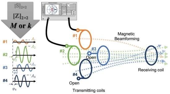
The conventional wireless power transfer (WPT) system with two coils has obvious limits; the system is very sensitive to the transmission distance and alignment between the coils [1,2]. To resolve these problems, adaptive or tunable matching networks have been adopted [3,4], and a transmitting module not with a single coil, but with multiple coils has been also introduced into the WPT system [5,6]. Especially, the magnetic beamforming, which focuses magnetic fields from the multiple transmitting coils to the receiving coil, has recently attracted lots of attention. For an ideal multi-coil WPT system, the coupling coefficients among transmitting coils should be zero, but in reality, they are not. The non-zero coupling coefficient among transmitting coils is one of the major causes of deterioration of the power transfer efficiency (PTE) in the magnetic beamforming. To minimize the effect of non-zero coupling coefficients, the phase and magnitude of signals input to transmitting coils should be adjusted to the optimum values that are estimated from the measured coupling coefficients among coils. The adjustment makes the all current of transmitting coils in phase, and results in a maximum receiver current and maximum PTE [5,6]. Therefore, the accurate and simple procedures for measurement of the coupling coefficient among multiple coils is essential for implementing the magnetic beamforming of a multi-coil WPT system.
For a WPT system with an operating frequency of a low-frequency (LF) band such as 110 to 205 kHz, the coupling coefficient (or mutual inductance) is usually measured by an LCR meter [7] or an impedance analyzer [8]. On the other hand, in a high-frequency (HF) band such as 6.78 or 13.56 MHz, most coils have a frequency-dependent characteristic due to the effect of ac resistance and parasitic elements. Therefore, a vector network analyzer is commonly used to measure the coupling coefficient in HF bands [9]. In the case of multi-coil WPT systems, the measurement issue arises primarily from the common vector network analyzer (VNA) having only two ports. Although a multiport VNA can measure the coupling coefficient among a greater number of coils, it is still only available for coils with equal or less than the number of ports.
In this paper, we simulate the effect of inaccurately measured coupling coefficients on the PTE of a multi-coil WPT system, and propose a method to readily measure the coupling coefficients among multiple coils using a two-port VNA based on the definition of the impedance matrix. In addition, this measurement method can overcome the limitation of the performance of a multi-port VNA for more coils than the number of ports. We verify the validity of the proposed method from the results that the proposed method has the same performance as conventional measurement methods according to distance.

2. Effect of Inaccurate Coupling Coefficient on PTE of a Multi-Coil WPT System

In this section, we simulate the PTE of a multi-coil WPT system with magnetic beamforming by applying inaccurate coupling coefficient information to examine the importance of an accurate coupling coefficient measurement.
Consider the multiple-input single-output (MISO) WPT system configured as four transmitting coils and a single receiving coil, where all transmitting coils are modeled as an inductance of 1.1 μH and a parasitic resistance of 0.4 ohm. Additionally, we assume that all coupling coefficients among transmitting coils are fixed to 0.05, and coupling coefficients between transmitting and receiving coils are also fixed to 0.05. The assumption that all coupling coefficients among transmitting coils are the same for all transmitting coils is difficult to realize in practice, but this assumption is effective in simulating the PTE of a multi-coil WPT system, because the input signals of all transmitting resonators have the same value when the magnetic beamforming algorithm is applied. Figure 1 shows the schematic diagram of the MISO WPT system for circuit simulation using the Keysight’s ADS (Advanced Design System).
To apply magnetic beamforming to the MISO WPT system, the voltage of transmitting coils must be given by [6]:
v T b f = ( Z T + ω 2 M T M R R ) i T b f ,
where M is the mutual inductance matrix between the transmitting and receiving coils; RR is the total resistance of the receiving resonator; i T b f is the transmit current and is proportional to M; and ZT is the inter-coupling matrix among transmitting coils and is constructed as the coupling coefficients (or mutual inductances) among transmitting coils. That is, the amplitude and phase of the transmit voltage is dominantly determined by coupling coefficient information. Therefore, the more accurate the coupling coefficient is, the more accurately the transmit voltage for the magnetic beamforming is obtained.
By applying the coupling coefficient with error term to the magnetic beamforming, we simulated the PTE degradation of the MISO WPT system at 13.56 MHz. The simulated results are shown in Figure 2. When the exact coupling coefficient of 0.05 is used for the beamforming, the PTE achieves about 77%. As the error rate of the coupling coefficient increases, the PTE decreases. Coupling coefficient error rates of 10% and 20% result in PTE degradations of 7% and 15%, respectively, compared with no error. Since the coupling coefficient among coils usually has a low level with 10−2 order, error rate of 10% means 10−3 order that is quite challenging to measure. Additionally, the larger the number of coils used in the HF band, the more difficult and cumbersome it is to measure the coupling coefficients. Therefore, a highly accurate measurement method of coupling coefficients with simple procedures is very important to achieve the ideal PTE of a multi-coil WPT system.

3. Conventional and Proposed Methods

This section presents conventional and proposed measurement methods of coupling coefficients among multiple coils. For the measurement of coupling coefficients, we use some assumptions. First, the measured coupling coefficient is not by electrical coupling but by magnetic coupling. In the case of the radio-frequency identification (RFID) with a few millimeters distance between coils, electrical coupling should be considered [10]. However, a WPT system in HF band with the transmission distance of several tens of centimeters usually considers only magnetic coupling. Second, the measured mutual inductance is not the ideal inductance, but the mutual inductance affected by the frequency and surrounding objects by parasitic elements. This is because the values used for the magnetic beamforming of the multi-coil WPT system are the mutual inductance affected by parasitic elements.

3.1. Conventional Measurement Methods

In HF bands, the conventional methods to measure coupling coefficients among three or more coils can be categorized into two types, namely, those that use multi-port and those that use two-port VNAs. The former method simply measures the n × n [S] matrix for n coils that are directly connected to ports of a multi-port VNA without an additional resonant capacitor. Then, the measured [S] matrix is converted into the [Z] matrix on an external PC. Consequently, the coupling coefficient between the ith and jth coils is obtained by:
k i j = M i j L i L j = Im { Z i j } Im { Z i i } Im { Z j j } ,
where Mij is the mutual inductance between the ith and jth coils, and Li and Lj are the self-inductances of the coils, respectively. Here, Zij is the ij entry of the [Z] matrix, and it is often referred to as the transfer impedance for i × j. The other conventional method repeatedly measures 2 × 2 [S] matrices for all possible sets of two coils, where the other coils must be terminated with a 50 ohm load from the definition of the S parameter, and then synthesize the n × n [S] matrix for the total n coils. This method is theoretically equivalent to the former method [11,12].

3.2. Proposed Measurement Method

From Equation (2), it is confirmed that the coupling coefficient is calculated using only elements of the [Z] matrix without the need for the [S] matrix. Furthermore, the calculation of kij requires only impedance parameters related to the ith and jth coils. The Z parameters, often called open-circuit impedance parameters, are measured or calculated by applying current to one port and measuring the resulting voltages at all other ports opened. That is, to obtain the impedance parameters related the ith and jth coils, the others port must be open-circuited. In addition, the required Z parameters can be obtained by converting the measured 2 × 2 [S] matrix into the 2 × 2 [Z] matrix.
Consider a transmitter array configured as four coils, as shown in Figure 3. To measure the coupling coefficient (k14) between coils 1 and 4, both the coils 1 and 4 are connected to a two-port network without any resonant capacitor, and all other coils are open-terminated. Because most VNAs provide a function to mathematically manipulate measured data, such as Keysight’s equation editor, we can immediately check the coupling coefficient between coils 1 and 4 on the display of the two-port VNA by converting a 2 × 2 [S] matrix to a 2 × 2 [Z] matrix and applying Equation (2).

3.3. Simplicity of the Proposed Method

Figure 4 shows the measurement procedures of the proposed method and two conventional methods for coupling coefficients among multiple coils. Method I using a multi-port VNA is very convenient because all relationships among coils are measured at once. However, if the number of coils is larger than the number of ports of the network analyzer, this method cannot be applied. Additionally, the measured high-order [S] matrix is not instantaneously converted to the corresponding [Z] matrix on the common VNA, so the [S] matrix should be saved in an SnP (touchstone) file format and converted on an external PC. Method II using a two-port VNA requires repetitive two-port measurements nC2 times for all possible sets of two coils and all unconnected coils terminated with a 50 ohm load. In addition, the total n × n [S] matrix should be synthesized using 2 × 2 [S] matrices. On the other hand, in the proposed method, only two coils are connected with a two-port VNA, and the coupling coefficient obtained from Equation (2) can be immediately checked on the display of the VNA according to the distance between coils. Additionally, this method is not limited to the number of coils. Therefore, the proposed method has very simple procedures.

4. Experimental Setup and Results

This section presents experimental setup and results to validate the proposed method.

4.1. Experimental Setup for Measurement

To simplify the problem, consider that there are three coils mutually coupled with each other. Figure 5 shows the experiment setup to verify the performance of the proposed method. Three coils were aligned co-axially. The coupling coefficients between the first and third coils were measured by changing the distance between the two coils in the HF band, in which the second coil was always located in the middle of the two coils. The parameters of the coils are summarized in Table 1. The coil with the inductance of 1.1 μH was designed to have an high quality factor of about 250 at 6.78 MHz, and it has three turns and a single layer printed on the FR-4 substrate, of which the dimension is 95.7 mm × 105.7 mm. The coil of 3.8 μH was fabricated to verify the proposed method for coils with high inductance, and it has six turns and two layers printed on the FR-4 substrate of the same dimension as the coil of 1.1 μH.

4.2. Changing Coupling Coefficient between Coils

Figure 6 shows the results measured by Method I using Keysight’s four-port VNA, E5071C, for Cases #1, #2, and only two coils without a middle coil. Ideally, the coupling coefficient between two coils must maintain a constant value regardless of the frequency and existence of other coils. However, as the distance between the farthest coils decreases, the measured coupling coefficients deviate from that of the two coils without a middle coil. The deviation increases further as the frequency increases and the inductance of the middle coil increases.

4.3. Comparison Results and Discussion

The coupling coefficients measured by the conventional and proposed methods with respect to the distance between the farthest coils are shown in Figure 7. We can notice that the proposed method produces almost the same results as the conventional methods. For a more accurate comparison, we calculated the mean and standard deviation of difference between the results of Method I and the proposed method, and the statistical results are summarized in Table 2. It is confirmed that both the mean and standard deviation are less than 0.001. This means that the proposed method provides precise and repeatable coupling coefficients among multiple coils.
Figure 8 shows the reactance of transfer impedances measured by the conventional and proposed methods with respect to the frequency at the distance of 8 cm and 16 cm between the farthest coils. In spite of the simple measurement procedure, the proposed method provides accurate results that are similar to those of the conventional methods. That is, the proposed method can be used to measure the transfer impedance, as well as the coupling coefficient.
Because the transfer impedance is ideally represented by Zij = jωMij, the transfer impedance should be proportional to the frequency. However, in reality, the transfer impedance is not linear for the frequency because of the effect of the parasitic components of the coil. These effects become stronger in Case #2 than Case #1 and at higher frequency than at lower frequency.
To validate the accuracy of the proposed procedure, the measured Z parameters were converted into the S parameters and they were compared with the results obtained from Methods I and II. First, in order to obtain a 3 × 3 [S] matrix from the proposed measurement method, a set of two coils was connected to a two-port VNA, and a 2 × 2 [Z] matrix was measured with the other coils open-circuited. For the other set of coils, 2 × 2 [Z] matrices were measured, and a 3 × 3 [Z] matrix was constructed by combining three 2 × 2 [Z] matrices. Finally, a 3 × 3 [S] matrix was obtained from a 3 × 3 [Z] matrix by applying conversion equations. Figure 9a,b shows the S13 from Methods I and II, and converted from the proposed method in a range from 1 to 15 MHz on the Smith chart and rectangular plot, respectively. S13 is the transmission coefficient from port 3 to port 1 when all other coils are terminated in matched load of 50 ohms. However, in reality, the coils of a WPT systems are not terminated with 50 ohms, and then S13 has no special physical meaning. Neverthless, the [S] matrix converted from the [Z] matrix obtained by the proposed method is in good agreement with the [S] matrix obtained by the conventional methods in the frequency range from the LF to HF band. This means that the proposed method provides accurate measurement results.
In the proposed method, the critical assumption is that unconnected coils with a two-port network analyzer must be perfectly open-terminated. In the measurement, we realized the open condition by un-connecting anything from the coil’s SMA connector. This method does not fully satisfy the assumption for wide frequency band or high frequency due to the parasitic capacitance of the SMA connector, whereas the un-connecting method can be still powerful at a low frequency, including LF and HF bands used in most WPT systems.
In order to investigate the effect of non-perfect open, we applied the proposed method to the measurement of the transfer impedance of three coils with open-termination and without any termination. The used open termination is the OPEN part of the Keysight’s 85052C, of which the error is less than ±0.65° for DC to 3 GHz. Figure 10 shows the normalized coupling coefficients with respect to frequencies that were obtained from the measured transfer impedance using Equation (2) and normalized to the maximum coupling coefficient for comparison of the effect of the open termination. The difference between the coupling coefficients of the two cases is within approximately 5%, except for around 20 MHz and 50 MHz, which are the self-resonant frequencies of the coils of 3.8 μH and 1.1 μH, respectively. In other words, this means that the proposed method provides reliable results without ideal open termination, but must not be used near the SRF of the coils. Since it is common to operate WPT systems at a lower frequency than the SRFs of coils, the proposed method can be effectively applied to measure the coupling coefficient or mutual inductance between the coils used in WPT systems.

5. Conclusions

In this paper, a coupling coefficient measurement method with a simple procedure was proposed to overcome the inconvenience and limitation of conventional measurement methods of coupling coefficients among coils in multi-coil WPT systems. To verify the potential of the proposed measurement method, a comparative analysis was performed by graph and mean and standard deviation values with the conventional measurement methods with respect to distance. As a result, the proposed method was demonstrated to achieve competitive performance with good accuracy. If the proposed method is applied to the magnetic beamforming of a multi-coil WPT systems, it can be a very powerful alternative to obtain prompt results.

Author Contributions

Conceptualization, D.-W.S.; methodology, D.-W.S.; software, S.-J.J.; validation, S.-J.J.; formal analysis, S.-J.J.; investigation, S.-J.J.; resources, S.-J.J.; data curation, D.-W.S.; writing—original draft preparation, D.-W.S.; writing—review and editing, D.-W.S.; visualization, S.-J.J.; supervision, D.-W.S.; project administration, D.-W.S.; funding acquisition, D.-W.S.

Funding

This work was supported by a National Research Foundation of Korea (NRF) grant funded by the Korea Government (MSIT) (No. 2018R1C1B6003854).

Conflicts of Interest

The authors declare no conflicts of interest.

References

  1. Kalwar, K.A.; Aamir, M.; Mekhilef, S. A design method for developing a high misalignment tolerant wireless charging system for electric vehicles. Measurement 2018, 118, 237–245. [Google Scholar] [CrossRef]
  2. Mao, S.; Wang, H.; Zhu, C.; Mao, Z.-H.; Sun, M. Simultaneous wireless power transfer and data communication using synchronous pulse-controlled load modulation. Measurement 2017, 109, 316–325. [Google Scholar] [CrossRef] [PubMed]
  3. Anowar, T.I.; Barman, S.D.; Reza, A.W.; Kumar, N. High-Efficiency Resonant Coupled Wireless Power Transfer via Tunable Impedance Matching. Int. J. Electron. 2017, 104, 1607–1625. [Google Scholar]
  4. Lee, J.H.; Seo, D.W. Adaptive Wireless Power Transfer System without Feedback Information using Single Matching Network. IEICE Trans. Commun. 2019, E102-B, 257–265. [Google Scholar] [CrossRef]
  5. Jadidian, J.; Katabi, D. Magnetic MIMO: How To Charge Your Phone in Your Pocket. In Proceedings of the 20th Annual International Conference on Mobile Computing and Networking (MOBICOM), Maui, HI, USA, 7–11 September 2014; pp. 495–506. [Google Scholar]
  6. Shi, L.; Kabelac, Z.; Katabi, D.; Perreault, D. Wireless Power Hotspot that Charges All of Your Devices. In Proceedings of the 21th Annual International Conference on Mobile Computing and Networking (MOBICOM), Paris, France, 7–11 September 2015; pp. 2–13. [Google Scholar]
  7. Acero, J.; Carretero, C.; Lope, I.; Alonso, R.; Lucia, O.; Burdio, J.M. Analysis of the mutual inductance of planar-lumped inductive power transfer systems. IEEE Trans. Ind. Electron. 2013, 60, 410–420. [Google Scholar]
  8. Theodoulidis, T.; Ditchburn, R.J. Mutual impedance of cylindrical coils at an arbitrary position and orientation above a planar conductor. IEEE Trans. Magn. 2007, 43, 3368–3370. [Google Scholar] [CrossRef]
  9. Fu, M.; Zhang, T.; Ma, C.; Zhu, X. Efficiency and optimal loads analysis for multiple-receiver wireless power transfer systems. IEEE Trans. Microw. Theory Tech. 2015, 63, 801–812. [Google Scholar]
  10. Hackl, S.; Lanschutzer, C.; Raggam, P.; Randeu, W.L. A Novel Method for Determining the Mutual Inductance for 13.56 MHz RFID Systems. In Proceedings of the 2008 6th International Symposium on Communication Systems, Networks and Digital Signal Processing, Graz, Austria, 25 July 2008; pp. 297–300. [Google Scholar]
  11. Tippet, J.C.; Speciale, R.A. A rigorous technique for measuring the scattering matrix of a multiport device with a 2-port network analyzer. IEEE Trans. Microw. Theory Tech. 1982, 30, 661–667. [Google Scholar] [CrossRef]
  12. Rolfes, I.; Schiek, B. Multiport method for the measurement of the scattering parameters of n-ports. IEEE Trans. Microw. Theory Tech. 2005, 53, 1990–1996. [Google Scholar] [CrossRef]
Figure 1. Schematic diagram of a multiple-input single-output (MISO) wireless power transfer (WPT) system for the advanced design system (ADS) circuit simulation.
Energies 12 03950 g001
Figure 2. Simulated power transfer efficiency (PTE) with respect to error rate of coupling coefficients between coils in the MISO WPT system.
Energies 12 03950 g002
Figure 3. Circuit diagram for measuring coupling coefficient between coils 1 and 4 for four coils using a two-port vector network analyzer (VNA).
Energies 12 03950 g003
Figure 4. Measurement procedures for the proposed and conventional methods.
Energies 12 03950 g004
Figure 5. Experimental setup for measuring the coupling coefficient of three coils.
Energies 12 03950 g005
Figure 6. Measured coupling coefficient using Method I for three coils of Cases #1, #2, and two coils.
Energies 12 03950 g006
Figure 7. Measured coupling coefficients of three coils as a function of distance using the conventional and proposed methods at 6.78 and 13.56 MHz: (a) Case #1 and (b) Case #2.
Energies 12 03950 g007
Figure 8. Measured transfer impedance Z13 as a function of frequency for the farthest distance of 8 cm and 16 cm using the conventional and proposed methods: (a) Case #1 and (b) Case #2.
Energies 12 03950 g008
Figure 9. S parameter results for three coils from the proposed and conventional methods at 8 cm: (a) Smith chart form and (b) real and imaginary values.
Energies 12 03950 g009
Figure 10. Measured normalized coupling coefficient at distance of 8 cm for open-terminated methods: (a) Case #1 and (b) Case #2.
Energies 12 03950 g010
Table 1. Parameters of coils used in measurement.
Coil 1Coil 2Coil 3
Case #1L = 1.1 μH
Rdc = 0.08 Ω
L = 1.1 μH
Rdc = 0.08 Ω
L = 1.1 μH
Rdc = 0.08 Ω
Case #2L = 1.1 μH
Rdc = 0.08 Ω
L = 3.8 μH
Rdc = 0.19 Ω
L = 1.1 μH
Rdc = 0.08 Ω
Table 2. Mean and standard deviation of difference between the results of Method I and the proposed method.
at 6.78 MHzat 13.56 MHz
MeanSt Dev.MeanSt Dev.
Case #14.1 × 10−45.21 × 10−45.11 × 10−43.75 × 10−4
Case #25.21 × 10−45.94 × 10−412.26 × 10−411.73 × 10⁻⁴