1. Introduction
The advantages of diesel engines are low CO
2 emissions and high fuel efficiency with respect to the output power. In general, ships use diesel engines as propulsion and auxiliary engines because various types of fuels can be employed. However, their emissions contain harmful particulate matter (PM) and NO
x (NO + NO
2). Therefore, exhaust purification requires aftertreatment technologies [
1]. These technologies have been extensively studied and developed in recent years, e.g., in our previous studies [
2,
3].
Reduction of NO
x from diesel emissions is difficult. However, emissions requirements have become increasingly stringent in recent years. The improvement of fuel injection in these engines has been investigated [
4]. To reduce NO
x emissions in O
2-rich environments, selective catalytic reduction (SCR) using urea solution or ammonia has been utilized [
5,
6,
7,
8,
9,
10,
11]. Some methods combine SCR with nonthermal plasma (NTP) [
12,
13,
14,
15,
16]. However, SCR requires a high temperature of 300 °C for catalyst activation, and there are issues regarding the production of nanoparticles, leakage of harmful ammonia, use of harmful heavy-metal SCR catalysts, and storage of the urea solution. Additionally, NO
x reduction technologies using NTP without a catalyst have been investigated [
17,
18].
Marine diesel engines are the next target of regulations. Normally, NO
x concentrations in the emissions of marine diesel engines are relatively high (500–1000 ppm), and the emissions contain SO
x (typically 100 ppm) in addition to PM [
2].
The regulations that govern marine diesel engines are specified by the International Maritime Organization (IMO) as explained for a rotation speed of 900 rpm in [
2]. In these regulations, the emission is restricted by the mass of NO
x emitted per unit of engine output energy for a given engine rotation speed, and is divided into Tiers I, II, and III according to the enforcement period. For a marine diesel engine with a rotation speed of 900 rpm, which is the target engine type in this study, NO
x emissions should be <11.5 g/kWh for Tier I in 2000, 9.20 g/kWh for Tier II in 2011, and 2.31 g/kWh in a NO
x- regulated emission area for Tier III in 2016. Therefore, a NO
x reduction of 6.89 g/kWh is required from Tier II to the current Tier III applied in 2016. This corresponds to a 75% reduction. Given the importance of NO
x emissions, more stringent regulations may be imposed on marine diesel engines in the future, which could require a similar amount of NO
x reduction.
Considering the circumstances of marine diesel emission and the emission regulations, NO
x treatment, as well as the removal of PM, must be urgently addressed [
19,
20,
21,
22]. In 2011, the main manufacturers of marine diesel engines were able to successfully satisfy the Tier II NO
x emission standards via combustion improvements. However, to satisfy the more stringent Tier III, an effective aftertreatment technology is indispensable. Urea-SCR technology is presently the most promising approach. However, it requires the storage of large amounts of urea solution inside the vessels. NO
x reduction via wet scrubbing using a chemical solution has also been investigated [
23]. However, it requires a tank of chemical solution in the ship, which has limited space.
In this study, an aftertreatment technology for NO
x reduction and PM treatment using NTP for a marine diesel engine is developed on the basis of our previous studies in a laboratory-scale experiment [
24,
25]. Considering practical use, experiments are performed for a larger number of cycles compared with our previous study to obtain more data. The objective is to obtain a more accurate relationship between the mass of desorbed NO
x and the mass of NO
x reduced by NTP with the data. The amount of adsorbent is 80 kg. Compared with SCR, this technology offers the advantages of eliminating the requirement of urea solution or harmful heavy-metal catalysts and operation at a temperature of <150 ºC. In our previous investigation [
3], PM and NO
x reductions were studied in the aftertreatment for a marine diesel engine with an output power of 610 kW. In another one of our previous studies [
2], NO
x reduction with NO
x adsorbents unused in the aftertreatment was investigated for a marine diesel engine with an output power of 1071 kW. In the present study, according to the results of our previous investigations regarding NO
x reduction [
2], experiments involving aftertreatment for a marine diesel engine with an output power of 1071 kW are repeated for a longer period (up to 19 cycles). In the aftertreatment, estimation of the NO
x reduction efficiency is significant for the design and operation of the system. Compared with the previous studies, considerably more data are obtained to provide a highly accurate estimation of the efficiency of NO
x reduction via NTP.
2. Operating Principle of NOx Reduction in Aftertreatment
In the previously reported technology [
2,
24,
25], given that NO
x cannot be efficiently and directly reduced by NTP under O
2-rich conditions, it is first adsorbed by adsorbents under O
2-rich conditions. After the adsorption, NO
x is desorbed by heating the adsorbents under O
2-lean (preferably O
2 < 2%) and fuel-rich (CO and hydrocarbon-rich) gaseous conditions. Switching the different processes is achieved by changing the exhaust path flows and by using the waste-heat recovery of the engine. The high-concentration NO
x desorbed from the adsorbents is effectively reduced to N
2 and N radicals by NTP. O
2-lean or N
2 gaseous conditions can be achieved using an O
2 penetration membrane or by controlling the engine operating mode (fuel-injection mode). The following chemical reaction for NO
x reduction is performed under O
2-lean conditions with NTP:
The NTP reactors should only be turned on when high concentrations of NO
x are desorbed and only during the short desorption period, reducing the required plasma energy. Laboratory-scale experiments based on this procedure in which NO
x was treated with a high energy efficiency were reported in our previous papers [
26,
27,
28,
29], and a related patent was filed [
30].
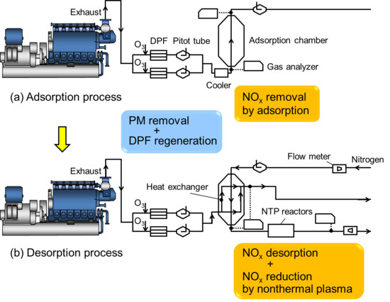
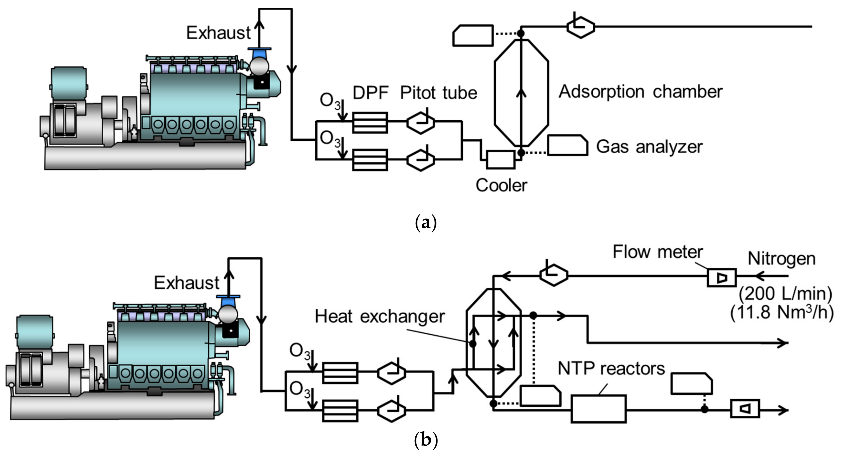
Figure 1 shows process diagrams of the PM and NO
x simultaneous reduction system for a marine diesel engine. Because the objective of the present study is to investigate the NO
x reduction efficiencies in a larger number of cycles compared with our previous study [
2], the experimental setup and processes are the same. The system mainly consists of the marine diesel engine, diesel particulate filters (DPFs), an adsorption chamber, and NTP reactors. PM reduction is first performed with a pair of DPFs, and the DPFs are regenerated via ozone injection. Next, NO
x reduction is achieved through two flow processes: an adsorption process followed by a desorption process combined with the NTP reaction. The sequential application of these two processes in the same adsorption chamber realizes continuous NO
x reduction. In the adsorption process, the flow rate of the exhaust gas determines the flow velocity, which is measured by pitot tubes. After the exhaust gas is cooled using a water-cooling-type cooler, it passes through the adsorption chamber, where NO
x is adsorbed by adsorbents. The NO
x concentrations are measured at the inlet and outlet of the chamber. In the desorption process, the exchanged waste heat is added to the adsorbent pellets via a heat exchanger to induce the thermal desorption of NO
x. Simultaneously, N
2 gas flows over the packed adsorbent pellets. Then, high concentrations of NO
x are desorbed from the chamber. The desorbed NO
x is reduced in the NTP reactor. Thus, the simultaneous reduction of PM and NO
x is achieved [
2]. In the next section, the experimental apparatus and results are presented.
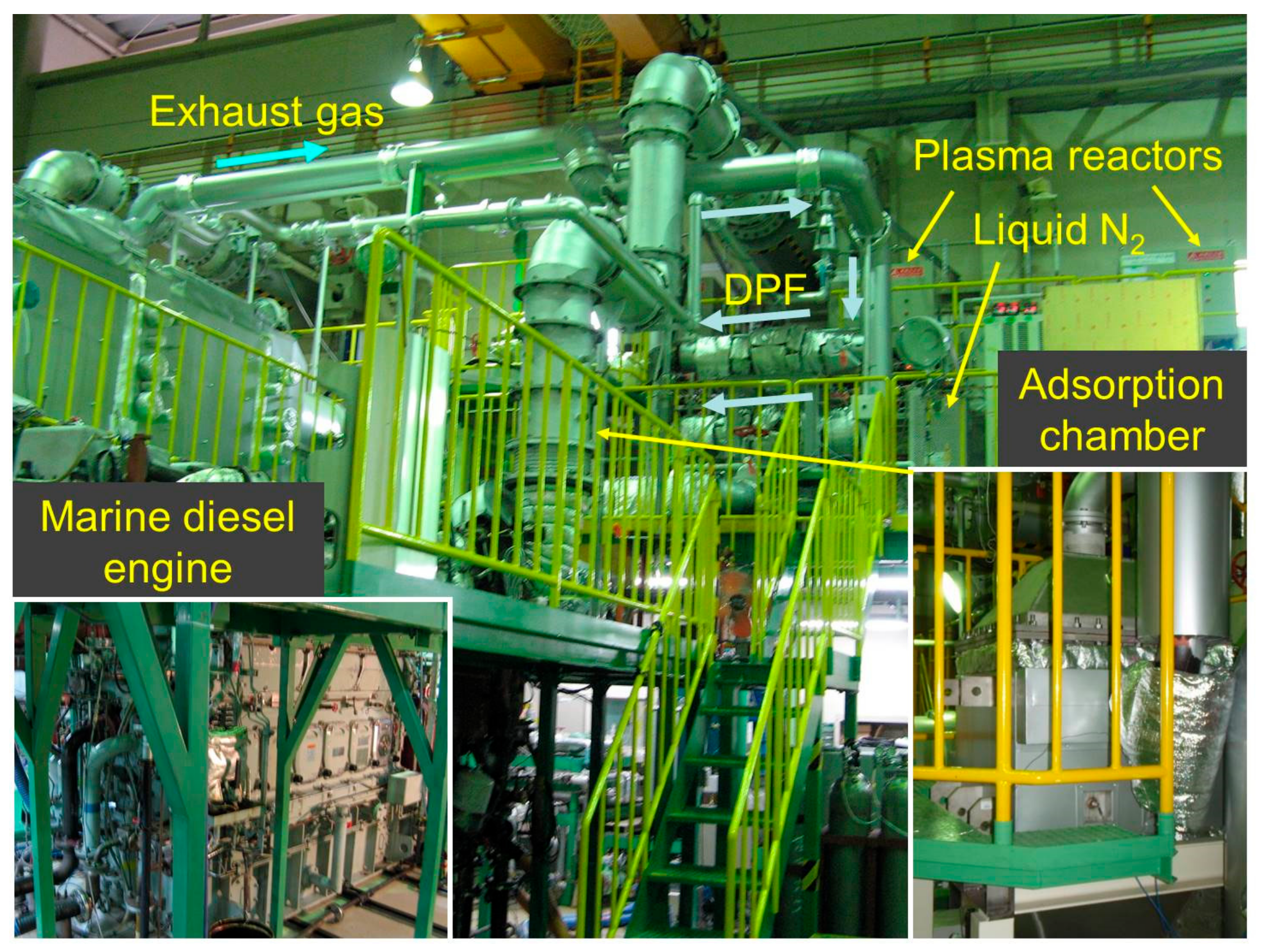
3. Experimental Apparatus
A photograph of the diesel engine (6DK-20e, Daihatsu Diesel MFG Co. Ltd., Japan) is shown in
Figure 2. Experiments are performed using an electrical sub-power generation marine engine bench in the laboratory.
Table 1 shows the specifications of the engine. The specifications are four strokes, six cylinders with a cylinder bore of 200 mm and a stroke of 300 mm, and a constant rotation rate of 900 rpm.
Table 2 shows the operating conditions. The maximum (100%) output power is 1071 kW. The fuel was marine diesel oil (A-heavy oil (the same grade as marine diesel oil), sulfur content = 0.075 mass%, nitrogen content = 0.01 mass%, heating value = 45.4 MJ/kg). The exhaust flow rate was 3920 Nm
3/h for 50% load or output power, 5526 Nm
3/h for 75%, and 6815 Nm
3/h for 100% (N denotes the standard state of 0 ºC, 0.1 MPa) [
2].
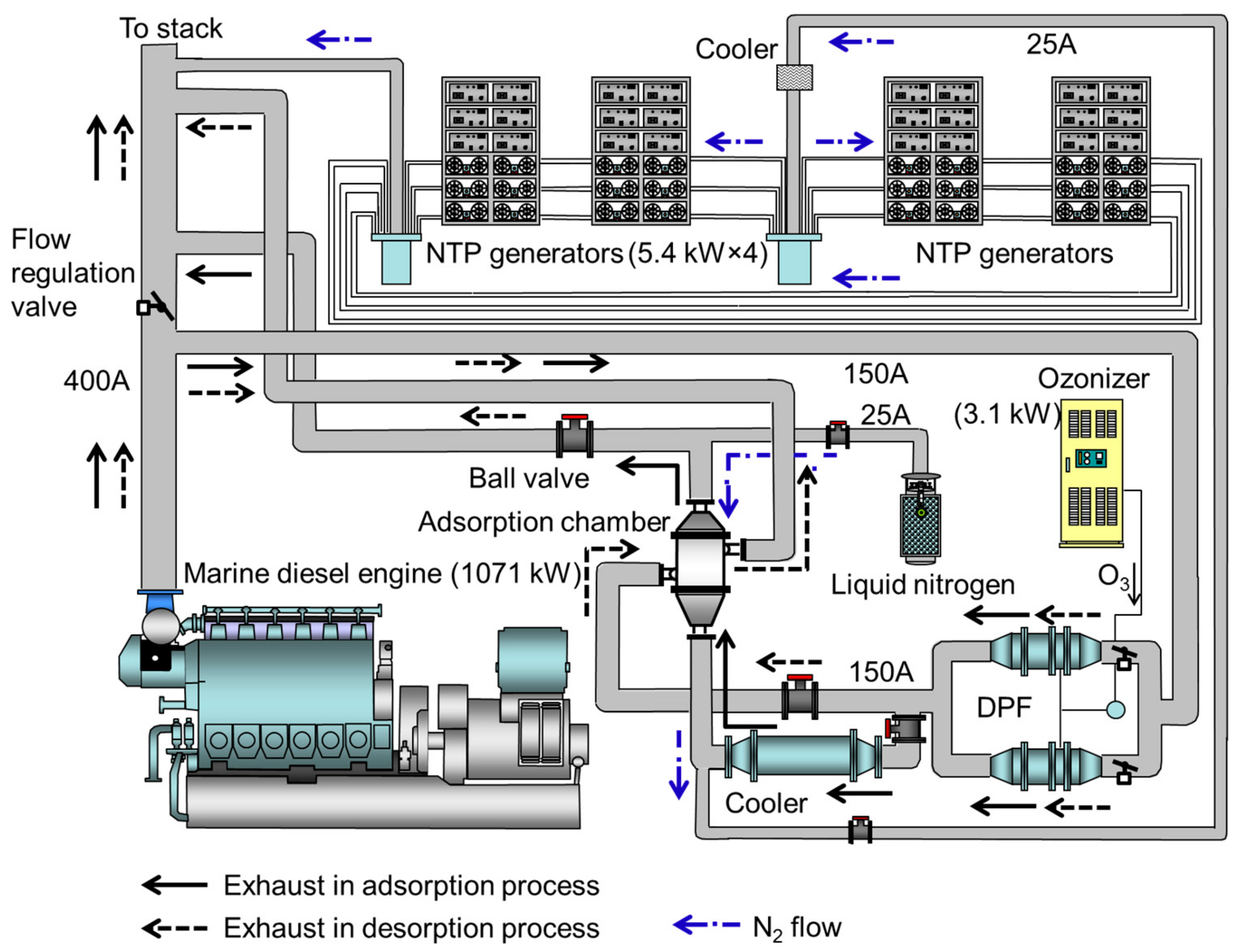
Figure 3 shows a schematic of the experimental setup for the aftertreatment for the marine diesel engine.
Figure 4 shows the experimental setup for exhaust-gas aftertreatment in the marine diesel engine system. Approximately 16% of the bypassed exhaust gas passes into a 150A pipe (in Japanese Industrial Standards; inner diameter = 155.2 mm) and through a set of ceramic DPFs (material: SiC, TYK Corporation, Japan). Here, most of the PM is removed. Subsequently, the flow velocity is measured by a set of pitot tubes (L type, FV-21A, OKANO WORKS, Ltd. Japan). The accumulated PM in the DPF is treated using NTP-induced ozone (O
3) injection technology, as we previously reported [
2,
31]. After the PM removal, the NO
x in the exhaust gas is treated via adsorption and desorption processes with NTP in the same way as the previous experiment [
2] as well as the measurements. The concentration of untreated NO
x from the engine is 400‒760 ppm, and the ratio of NO
2/NO
x is approximately 15%. N
2 gas at a low flow rate in the desorption process is 11.8 Nm
3/h (200 L/min at 5 ºC). A significantly higher concentration (typically 3660‒25,000 ppm) of NO
x compared with that of the previous study (typically 4000 ppm) [
2] flows out of the chamber and enters the NTP reactors, with a total energy consumption of 12.0 kW. NO
x is reduced into N
2 and O
2 according to reaction (1). As the upper limit of the analyzer is 2500 ppm, high-concentration desorbed NO
x gas in excess of 2500 ppm is diluted with atmospheric air. The actual NO
x concentration is estimated by comparing the O
2 concentration of the diluted exhaust gas with that of the raw exhaust.
Figure 5 shows the adsorption chamber equipped with a waste-heat exchanger that is specially designed and manufactured by Sumitomo Precision Products Co. Ltd. (type: XS6083). The directions of gas flow and the dimensions are shown. The same chamber that was used in a previous experiment is employed [
2]. The adsorption chamber is designed optimally based on our results of the laboratory-scale experiment [
25] and the previous pilot-scale ones [
2,
3]. The amount of packed adsorbent pellets is 80 kg, which represents 101 L by volume. Compared with the previous study [
3], the dimensions of the chamber are different, and the cross-sectional area is 3.9 times larger. However, the vertical length is 0.7 times shorter. The volume of the adsorption chamber including relevant externals is approximately 0.5 m
3, which is smaller than the typical volume of 6.0 m
3 of a urea-solution tank. The mass of the adsorbent chamber without adsorbents is almost equal to that of empty urea-solution tank.
Figure 5a shows a cross section of the chamber with two types of flow paths—flow path I (the number is 47, and each gap is 3.2 mm) and flow path II (the number is 48, and each gap is 8.9 mm)—alternately stacked inside.
Figure 5b shows a side view of flow path I, in which the hot exhaust gas flows. Flow path I is empty, and flow path II is packed with adsorbent pellets, as shown in
Figure 5c. In the adsorption process, while exhaust gas flows from the bottom inlet to the top outlet of flow path II, NO
x is adsorbed onto the pellets. In the desorption process, heated exhaust gas travels along flow path I to heat the adsorbent pellets. Simultaneously, N
2 gas from a liquid N
2 cylinder flows from the top inlet to the bottom outlet of flow path II at a low flow rate to achieve O
2-lean condition, as shown in
Figure 5b,c. Switching between these two processes is performed by opening and shutting the ball valves. The adsorbent used in this study is a MnO
x–CuO oxidative compound (N-140, 1.2–2.4 mm-sized granular pellets, Süd-Chemie Catalysts Japan, Inc.). The measurement points for the adsorbent temperature are shown in
Figure 5c. The temperatures measured at these points are averaged for evaluating the efficiencies.
Table 3 presents the design specifications of the adsorption chamber. A counter-flow-type heat exchanger is used in the adsorption chamber. The design specifications are the same as those used in a previous study [
2]. Thus, the total heat-exchange quantity is 61.2 kW. The pressure drop and space velocity are also presented in the table. When the amount of packed adsorbent pellets is 40 kg, the space velocity is higher than that in our previous study [
3], with a ratio of 1.96 (i.e., 16,000/8150).
Figure 6 shows a photograph and schematic of the NTP reactor used for reducing NO
x. The reactor consists of a surface-discharge element (ET-OC70G-C, Masuda Research Inc., Japan), air-cooling fins, and a flange to fix the discharge element to the frame. The structure of surface discharge is also presented in the figure. As shown, NO
x in the N
2 gas flows on the surface-discharge element. NO
x is reduced to the clean gases of N
2 and O
2 with the surface discharge plasma. The surface-discharge element is cooled with an air-cooling fan. The specifications of one unit of the NTP generator in
Figure 3, which includes the power supplies and the NTP reactors, are as follows. Two of these reactors are powered by a single-pulse high-voltage power supply (HCII-70/2, Masuda Research Inc.). The maximum peak-to-peak voltage is 10 kV, with a frequency of 10 kHz. The maximum input power is 450 × 2 = 900 W. A unit of the NTP generator (HCII-OC70×12) consists of 12 NTP reactors and six power supplies. The total input power of a unit is 900 W × 6 = 5.4 kW, and the discharge power is 5.0 kW.
4. Results and Discussion
Experiments are performed for 19 operation cycles. The NOx reduction performance in the aftertreatment is evaluated. The engine operation was stopped once during each process.
Figure 7 shows the time-dependent NO
x emissions before and after the gas passes through the aftertreatment for cycles 16–19. Cycles 16–19 represent the transition of the adsorbent from the unsteady state to the steady state. The engine load is set as 75% for all adsorption processes and 50% for all desorption processes, considering the exhaust-gas temperatures for the adsorption and desorption of NO
x. This setting of the engine load is chosen to investigate the performance in a severe condition because it gives the severe condition for the aftertreatment, that is, high concentration of NO
x in adsorption and lower temperature in desorption processes. The amount of adsorbent pellets in the adsorption chamber is 80 kg. The mass flow rate for NO
x, which is shown on the vertical axis in
Figure 7, is evaluated according to the molecular mass of NO
2, with the unit of g(NO
2)/h. Untreated NO
x in the adsorption process is represented by white circles with lines. Treated NO
x is represented by black circles with lines. NTP is applied only in the desorption processes, and the input power to the NTP generator is 12.0 kW. The mass flow rate of NO
x in the untreated exhaust gas is 1330–1500 g(NO
2)/h in the steady state of engine operation. The engine operation is stopped at
t = 3900 min in the adsorption process of cycle 17 and at
t = 4192 min in the adsorption process of cycle 18. Each stoppage lasts for approximately half a day. It is noted that the difference in the duration of the desorption is just due to the engine operation timing. In the adsorption processes, the mass flow rate of NO
x decreases to 970–1280 g(NO
2)/h. In the desorption processes, the maximum concentrations of desorbed NO
x are 8180, 11,380, 3660, and 17,830 ppm in cycles 16–19, respectively. On average, 49% of the desorbed NO
x is reduced by the application of NTP. For example, considering cycle 19 in the graph, similar to the previous report [
2], the hatched area represents the total mass of adsorbed NO
x, and the area in the desorption process represents the total mass of NO
x reduced by the NTP. The desorption of NO
x is enhanced in cycle 19.
Figure 8 shows the time-dependent temperature of the adsorbent pellets in cycles 16–19. At the beginning of each adsorption process, the adsorbent temperature is high because of residual heat from the previous desorption process. However, the temperature rapidly decreases to 50 ºC under cooling. The exhaust gas is exceptionally uncooled at the beginning and is cooled at
t = 3606 min in the adsorption process of cycle 16. Therefore, the temperature of the adsorbent pellets is high and becomes constant at
t = 3606 min in cycle 16. The temperature decreases at
t = 3900 min in the adsorption process of cycle 17 and at
t = 4192 min in the adsorption process of cycle 18 because the engine is stopped for approximately half a day. Consequently, the appropriate temperatures are achieved for both the adsorption and desorption processes.
Table 4 shows the resulting adsorbed, desorbed, reduced, and treated amounts of NO
x in cycles 16–19, as well as the gaseous flow rates and energy efficiencies in aftertreatment. The adsorbed mass of NO
x,
Wa, ranges from 855 to 1651 g(NO
2). The desorbed mass of NO
x,
Wd, ranges from 41.4 to 160 g(NO
2). The mass of NO
x reduced by the application of NTP,
WNTP, is in the range of 17.3–114 g(NO
2). The total amount of NO
x removed by the system is calculated as
The energy efficiency of the NTP treatment, which shows how to efficiently treat a mass of NO
x per unit of energy, is calculated as follows.
where,
ENTP represents the applied NTP energy.
ηNTP is determined to be 1.1–8.1 g(NO
2)/kWh. The NO
x removal energy efficiency of the system is calculated as
The present technology exhibits the highest system energy efficiency, i.e., ηsystem = 115 g(NO2)/kWh, in cycle 19. The low NTP power of 12.0 kW contributes to this high efficiency. In the adsorption process of cycle 19, the typical concentrations of gaseous NO2, NO, CO, and O2 downstream of the adsorption chamber are 100 ppm, 430 ppm, 69 ppm, and 13.9%, respectively. In the desorption process of cycle 19, the NOx concentrations upstream and downstream of the NTP generator are 5610 and 1620 ppm, respectively.
Figure 9 shows the relationship between the mass of desorbed NO
x and the reduction energy efficiency in the NTP treatment in the desorption processes of cycles 16–19. The data for the desorption processes of cycles 5–12 of the previous experiments [
2] are also shown. Cycles 13–15 are not shown, because NO
x reduction via NTP is not performed. The data plots are presented with the time period of the desorption process. The relationship between the reduction and the mass of desorbed NO
x is approximately given by the line of
The coefficient, 0.0442, is improved compared with that reported in the previous study [
2], because it is determined using a larger amount of data in repeated experiments. Furthermore, a high reduction efficiency of 71% is achieved in cycle 19 for the discharge power of 12.0 kW. The efficiency of reduction via NTP,
ηre, is defined as the ratio of the amount of reduced NO
x to the amount of desorbed NO
x:
The system energy efficiency of
ηsystem = 115 g(NO
2)/kWh is lower than
ηsystem = 161 g(NO
2)/kWh observed in the previous study [
2]. This is because the previous investigation is performed by exploiting the high-adsorption performance of relatively new adsorbents. However, the present study is conducted in the steady state of the adsorption and desorption of NO
x, in which the adsorption performance decreases. However, the desorption performance and efficiency of NO
x reduction via NTP are higher those in the previous study. For a marine diesel engine with a rotation speed of 900 rpm, NO
x emissions should be reduced by 6.89 g/kWh to satisfy the IMO emission standards from Tier II to III. The recorded energy efficiency of the system (
ηsystem = 115 g(NO
2)/kWh) corresponds to only 6.0% (6.89/115 × 100) of the engine output power satisfying the requirement. Thus, the high-performance aftertreatment using the present technology satisfies the most recent IMO emission standards.

 ,
, 


