Article

Enhancement of Mist Flow Cooling by Using V-Shaped Broken Ribs

Department of Mechanical Engineering, National Chiao Tung University, Hsinchu 30010, Taiwan
*
Author to whom correspondence should be addressed.
Energies 2019, 12(19), 3785; https://doi.org/10.3390/en12193785
Submission received: 22 August 2019 / Revised: 26 September 2019 / Accepted: 1 October 2019 / Published: 6 October 2019
(This article belongs to the Special Issue Experimental Heat Transfer in Energy Systems)

Abstract

:
Substantial heat transfer enhancement can be achieved by cooling with air/water mist flow because of droplet impingement and liquid film/fragment evaporation on the heated surface, which leads to a high heat-removal rate. An experimental investigation was conducted in a square channel with continuous and broken V-shaped ribs. To generate a mist flow, micro droplets were introduced into the gas stream. The rib angle of attack was 45°, and the rib spacing-to-height ratios were 10 and 20. The air Reynolds number ranged from 7900 to 24,000, and the water-to-air volume flow ratio was less than 0.1%. The net heat inputs ranged from 1.1–3.1 W/cm2 and 3.4–9.4 W/cm2 for the air and mist flow cases, respectively. Because the deposited liquid fragments produced uneven temperature distribution on the heated surface, steady-state infrared thermography was used to visualize the heat transfer distribution. Two to seven times higher heat transfer was attained for the broken ribs when using the mist flow than when using air flow. This increase was mainly attributed to the broken structure, which facilitated liquid transport and enhanced liquid coverage. In addition, the broken ribs produced a smaller friction factor than continuous ribs. The broken structures were beneficial for higher thermal performance in the mist flow.

1. Introduction

Air/water mist flow is commonly used in engineering applications, such as heat transfer enhancement, evaporating cooling, and steel-making processes. Mist flow cooling is generated by adding micro droplets in the gas stream. Droplet deposition and liquid film evaporation on the heated surface substantially enhance the heat transfer. The mist flow cooling performance is dependent on the droplet size, concentration, temperature, and surface structure. The literature results have indicated that mist cooling outperforms air cooling and that the cooling performance is highly dependent on the droplet size and surface temperature [1,2,3]. In addition to a plane surface, surface roughness is also beneficial for entrapping liquids and increasing the heat transfer area, which leads to an increased heat transfer rate. For the flow over tube banks, a micro-finned tube achieves higher heat transfer coefficients than a smooth tube does [4]. In addition, the mist flow over smooth tubes can be further enhanced with grooved tubes, which promote surface wetting and liquid accumulation on the tube surface [5,6]. To obtain superior cooling performance, thin liquid films are preferred over thick liquid films or a dryout surface. In addition, mist cooling achieves uniform surface temperature distribution. A previous study suggested that an optimum droplet size ranging from 30 to 80 µm could generate desirable thin liquid films [7].
Ribs are commonly used to achieve enhanced convective heat transfer for internal cooling channels, heat exchangers, and solar air heaters. Ribs are generally used for single-phase flow cooling because they promote flow mixing and create an additional heat transfer area. Various parameters affect the rib heat transfer performance, namely the rib shape, rib spacing (P), rib height (e), rib configuration, and channel hydraulic diameter. Among the rib configurations, V-shaped or wavy ribs attain a higher heat transfer and thermal performance than other ribs. For heat transfer in a square channel, the 60° V-shaped ribs have the highest heat transfer at a rib spacing-to-height ratio of 10. Therefore, these ribs are recommended to replace 45° or 60° full ribs for internal cooling [8]. V-shaped ribs produce a higher heat transfer augmentation than parallel ribs, crossed ribs, and 90° ribs [9]. The Nusselt number ratio decreases when the friction factor ratio increases with increasing Reynolds number. In addition, broken ribs produce a higher heat transfer than continuous ribs [10]. The 60° V-shaped ribs exhibit maximal heat transfer enhancement for solar air heaters with an absorber plate [11]. The heat transfer enhancement is mainly caused by flow separation, reattachment, and the generation of secondary flows. V-shaped ribs can enhance the heat transfer coefficient of a rectangular duct by 110−147% compared with that of a smooth duct [12]. The experimental investigation of heat/mass transfer in rectangular channels with V-shaped ribs revealed that a high transfer region was formed at the center of the ribbed wall due to two pairs of counter-rotating vortices generated in the channel [13]. However, a previous study suggested that V-shaped interrupted ribs are less effective compared with V-shaped continuous ribs [14].
The aforementioned studies indicate that V-shaped ribs with attack angles of around 45−60° are effective for heat transfer enhancement. Therefore, including these V-shaped ribs in the mist flow channel can be beneficial for heat transfer improvement because they entrap liquid droplets and increase surface wetting. However, the presence of ribs or fins in the mist flow can block water droplets and hinder liquid film formation on the heated surface [15,16]. The objective of the current study is to investigate a new broken rib pattern which attained higher heat transfer enhancement and lower frictional loss for mist flow condition. The broken region can be used as a drainage passage that can substantially increase surface wetting and liquid film accumulation. A similar concept is useful for enhancing condensation heat transfer because of the enhanced droplet removal [17,18]. Infrared thermography is used to measure the detailed heat transfer distribution for determining the heat transfer variation caused by the impact of a droplet/liquid on the heated surface.

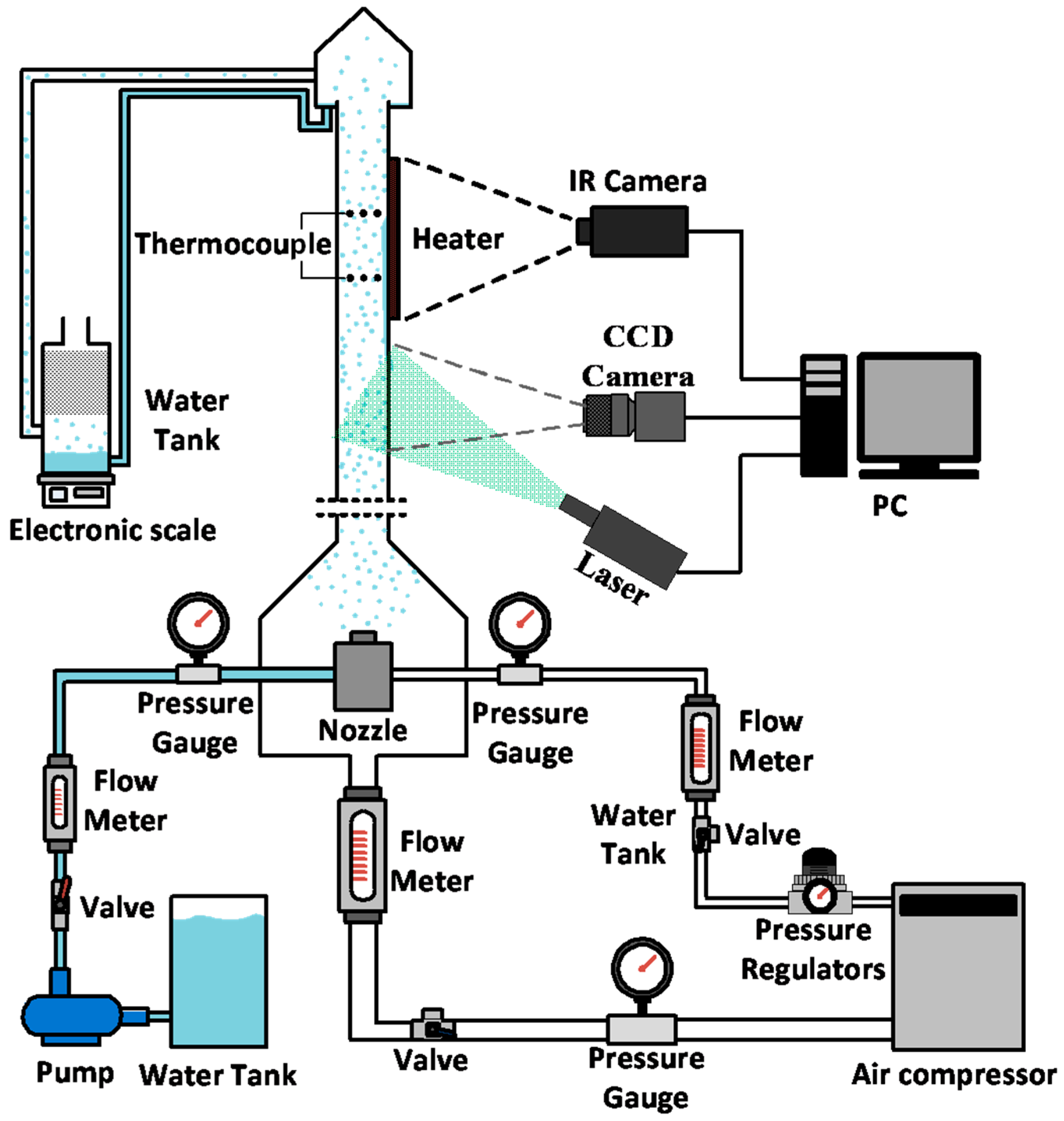
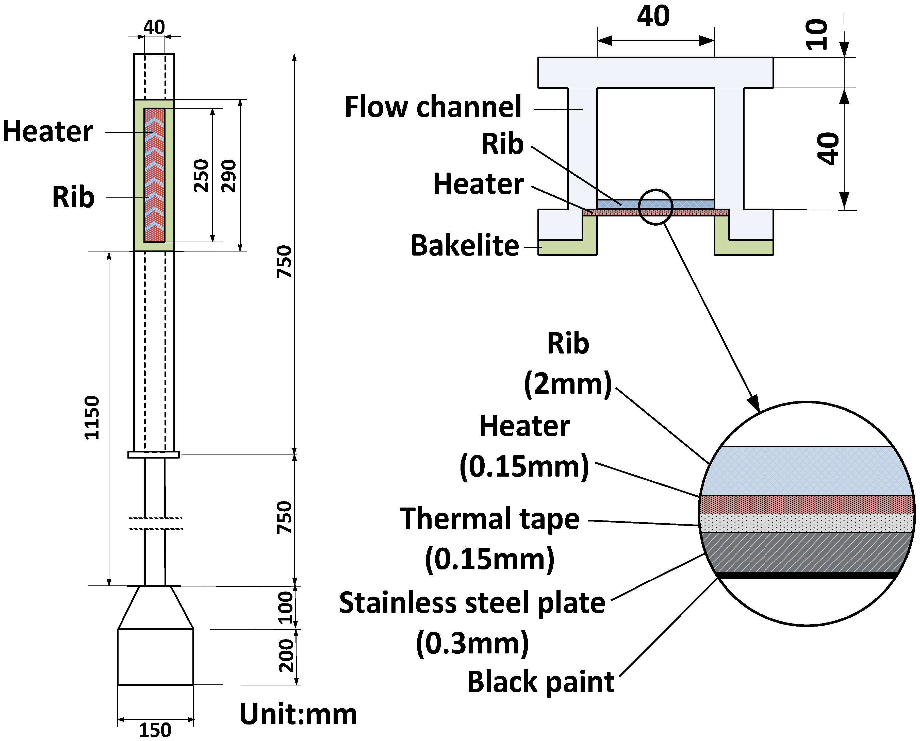
2. Experimental Setup and Methods

The mist flow channel and experimental setup are shown in Figure 1. The test channel is formed of Polyvinylchloride (PVC), which provides direct visualization of the mist/liquid fragments. An atomizing nozzle is used to generate the water spray and is mixed in a chamber at the entrance of the test channel. The droplet characteristics can be varied by adjusting the atomizing pressure. The two atomizing conditions used in this study are presented in Table 1, showing the liquid flow rate of the mist flow at the inlet and outlet of the test section. The two atomizing conditions produce different mist flow conditions and the liquid droplets are carried upward with the mainstream flow. The mainstream flow is collected and estimated at the top end of the channel. The source of the carrier flow is an air compressor, and the air/water mist flow is produced. The water flow into the channel is collected at the inlet and outlet of the channel. A dummy collecting piece is attached to the outlet of the mixing chamber to measure the corresponding water flow rates through the channel. Heat is supplied on one side of the channel, and the temperature is measured using an infrared camera (FLIR A325sc, Wilsonville, Oregon, USA) with a resolution of 320 × 240 pixels. During the heat transfer experiment, the fluid temperature is measured using the thermocouples installed at the inlet and outlet of the test channel. The droplet size within the mist flow is measured using an interferometry-based method, which is called global sizing velocimetry (GSV), at the entrance of the heated region. The GSV was developed using Lorenz-Mie theory and the Finely Stratified Sphere Scattering model, and this technique is not sensitive to the droplet refractive index. The average droplet diameter ranges from 50 to 60 μm.
The test channel has a square cross section with an area of 40 × 40 mm2, as displayed in Figure 2. The mist flow from the mist chamber is passed through a 1,150-mm-long straightener, which promotes the development of the flow. The measurement region downstream of the entrance straightener is 750 mm long, and the heated region is 250 mm long. The channel wall was heated using a resistance foil heater with alternating current. To prevent heater deformation, the heater element is attached to a 0.3-mm-thick stainless-steel foil and a 0.15 mm-thick high-thermal-conductivity tape. The infrared camera captures the surface temperature on the outside of the heater, and the temperature difference within this heating element is estimated using a thermal resistance model [15,16]. The measured difference was within 1.5 °C.
The 45° V-shaped ribs are selected as demonstrated in Figure 3. The rib height is 2 mm, which gives a rib spacing-to-height ratio (P/e) of 10 and 20 for rib pitches of 20 and 40 mm, respectively. The temperature measurement region is marked by a dashed line, which corresponds to the actual size of 65 × 36 mm2. The average surface temperature is maintained at 60 °C for each Reynolds number. The convective heat transfer coefficient is determined using Newton’s law of cooling as follows:
h = Q i n Q l o s s A ( T w T b )
The heater supplies uniform heat flux (Qin) to a heating area of 40 × 250 mm2. The net heat input ranges from 1.1–3.1 W/cm2 for the air flow case and 3.4–9.4 W/cm2 for the mist flow case. The heat loss (Qloss) is estimated using the measured heat input during the no flow condition, which accounts for the primary conduction and external natural convection heat losses. The heat loss is then calculated according to the heat input and the temperature difference between the surface and the surroundings (Tamb) as shown in Figure 4 [15,16], and the maximal heat loss accounts for 30% of the heat input into the test section at the lower Reynolds number (air flow case). The flow temperature is determined using the average temperature from three thermocouples at the inlet and outlet. The local bulk temperature (Tb) is linearly interpolated from the inlet and outlet temperatures along the streamwise direction for each pixel on the measurement plane. The steady-state condition is determined because the wall temperature variation from the infrared measurement is less than 0.5 °C. Therefore, the Nusselt number can be calculated according to the measured heat transfer coefficient as follows:
N u = h D h k a
Because the volume fraction of the disperse phase was extremely low (<0.1%), the effective thermal conductivity was literally equivalent to the thermal conductivity of the continuous phase. The pressure drop was experimentally measured using the pressure difference at the inlet and outlet, and the friction factor was calculated based on the following equation:
f = P ( L / D h ) 1 2 ρ V 2
An uncertainty analysis for the heat transfer measurement was conducted using Moffat‘s [19] method, and the uncertainties in the test parameter were listed in Table 2. The uncertainty in the Nusselt number was evaluated using the following equation:
Δ N u N u = 1 N u [ ( N u h Δ h ) 2 + ( N u D h Δ D h ) 2 + ( N u k a Δ k a ) 2 ] 1 2
The highest uncertainty in the Nusselt number was found to be 6%.

3. Results

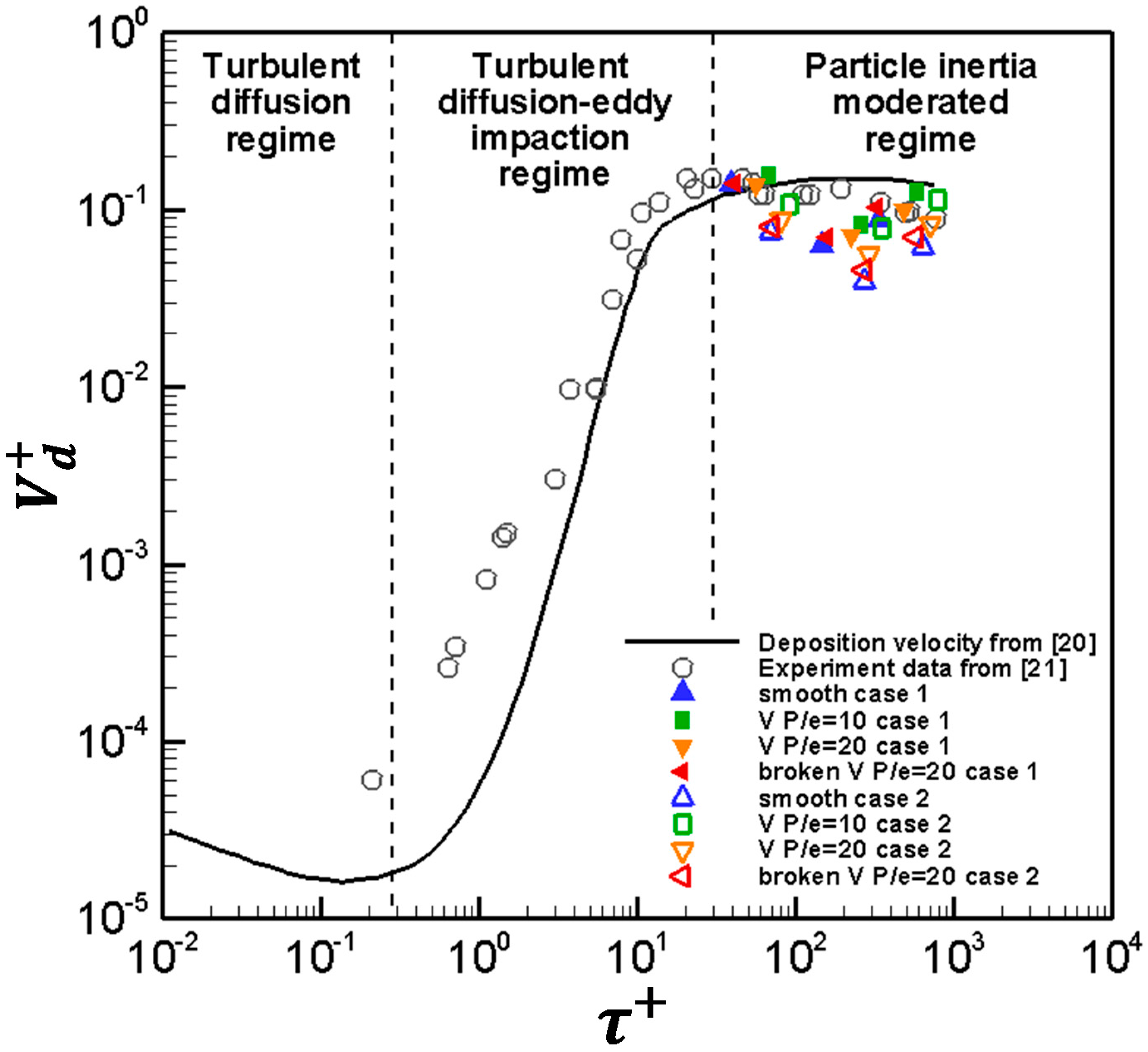
3.1. Mist Flow and Deposition Efficiency Calculation

The mist flow pattern was observed by manipulating the atomizing pressure and flow rate. The deposited droplets accumulated and move toward both sidewalls because of gravity, which resulted in considerable liquid fragments and downward dripping. As the liquid flow rate increased, the entrapped liquid fragments were enlarged. The results indicate that the liquid passing through the channel was affected by the rib structure. The water-to-air volume flow ratio was low (< 0.1%), and the water content was gradually evaporated through the heat transfer process. The excess liquid was collected at the end of the channel, and the broken ribs attained the largest liquid flow rates because of the facilitated liquid transport (Table 1).
To understand the dispersed particle/droplet in a turbulent flow transported towards the solid wall, the droplet deposition and relaxation time are commonly employed. The droplet deposition behavior can be investigated using the dimensionless deposition velocity ( V d + ), which is based on the deposition velocity ( V d ) and frictional velocity (u*) [16].
V d + = V d u * = V 4 D h L l n ( 1 F ) u *
where the deposition velocity is estimated using the air flow velocity (V) in the channel and fractional deposition (F). The factional deposition is calculated using the droplet mass flow rate measured at the inlet ( M i ) and outlet ( M o ) of the channel.
F = M i M o M i
The velocity lag between the droplet and air flow can be expressed using the droplet relaxation time ( τ + ) as follows:
τ + = d p 2 ρ c ρ d u * 2 18 μ 2
where the droplet diameter ( d p ) is obtained from the GSV measurement and the densities of the continuous phase ( ρ c ) and discrete phase ( ρ d ) are accounted for by the air and droplet, respectively. Figure 5 displays the correlation between the deposition velocity and relaxation time in the current study with the literature data from the vertical pipe flow [20,21]. The figure indicates that the results of the current study are mostly within the particle-inertia-moderated regime, where a strong inertia force was generated due to the increased droplet size. This strong inertia contributed to the weakened turbulent diffusion effect and decreased the deposition coefficient. The rib structure was beneficial for droplet deposition, and an intense rib structure increased the deposition efficiency. In addition, the increased liquid flow rate (case 2) caused a higher friction coefficient, which lead to a decreased deposition coefficient and increased relaxation time.

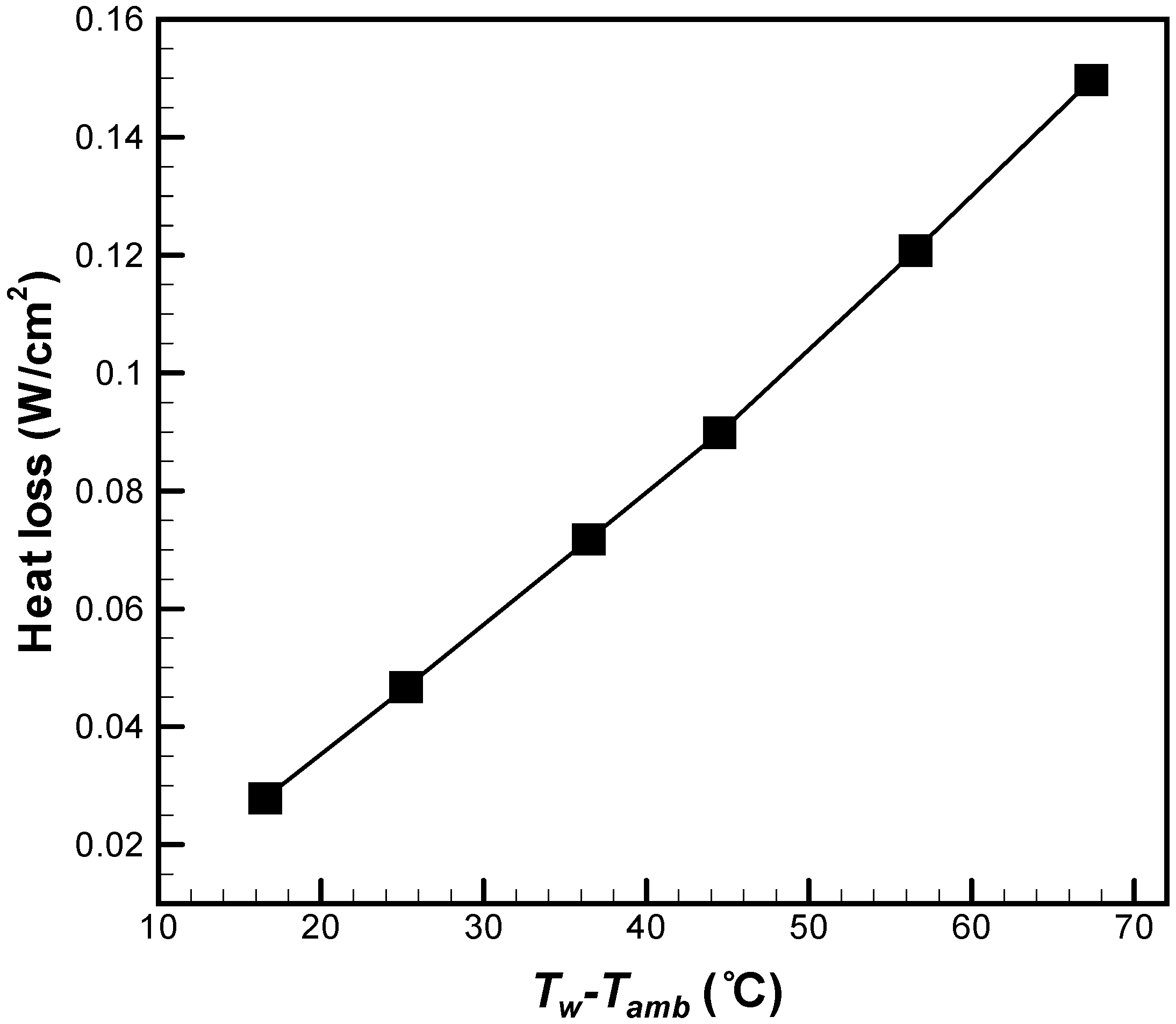
3.2. Heat Transfer Distribution from the Air Flow

To provide a baseline study, the Nusselt number distribution for the air flow was determined (Figure 6). The heat transfer was noticeably enhanced at discrete locations due to the ribs. At a small spacing of the V-shaped ribs (P/e = 10), high Nusselt numbers were observed at the sidewall of the channel, where the secondary flow induced by the ribs began to develop. Consequently, a decreased heat transfer was observed at the middle of the channel. For an increased spacing of the V-shaped ribs (P/e = 20), the secondary flow induced by the ribs was noticeably observed along the rib orientation toward the vertex of the V-rib. Due to the increased spacing, some regions not covered by the secondary flow exhibited lower heat transfer (approximately 13% lower than that in the P/e = 10 case). Generally, a large rib spacing is not beneficial for the overall heat transfer because some of the regions cannot benefit from the secondary flow effect. For the broken V-shaped rib, the augmented heat transfer spots decreased in size because of the shortened rib length, which caused weakened secondary flows. In addition, the broken V-shaped ribs produced a decreased heat transfer along the middle of the heated wall because of the direct flow passing through this region. The overall Nu values were 14% lower than those for the P/e = 20 case. Symmetrical heat transfer distribution was observed for all the ribs.

3.3. Nusselt Number Distribution for the Mist Flow

Mist flow tests were performed at three Reynolds numbers and two liquid-to-air flow ratios. For the V-shaped rib with P/e = 10 (Figure 7), although liquid droplets/fragments were frequently observed on the heated surface, the heat transfer distribution was fairly continuous because of the thermal equilibrium between the droplet and wall. In addition, an increased Reynolds number caused additional droplets to be carried across the vertical channel and promoted liquid film/fragment deposition on the heated surface, which substantially enhanced the heat transfer. The accumulated droplets/fragments occasionally slipped downward due to gravity, which also improved the heat transfer. An increased Reynolds number increased the droplet accumulation rate, which improved the liquid film coverage and promoted heat transfer. On the ribbed surface, spots with enhanced heat transfer were observed at the side wall of the channel because of the accumulated liquid. In the middle of the channel, the vertex of the V-ribs was not beneficial for liquid accumulation. Therefore, a low heat transfer was observed in the middle part.
According to the literature, intense rib patterns may cause strong secondary flow and break the liquid film coverage, which is not beneficial for heat transfer [15]. A higher heat transfer was attained when P/e was 20 than when P/e was 10 because additional liquid was deposited on the smooth wall, as illustrated in Figure 8. However, the flow reattachment region produced decreased Nu values along the rib orientation because it impaired the liquid films on the surface. Liquids were accumulated on the sidewall of the channel, where strong flow mixing did not occur. At the highest Reynolds number of 24,000, the increased liquid content on the surface caused the liquid to move downward, which enlarged the spots with increased heat transfer. In addition, increasing the liquid ratio by either increasing the gas flow rate or by changing the atomizing pressure can suppress the reattachment flow/secondary flow effects from the ribs, which causes increased heat transfer enhancement on the surface.
To improve the liquid film coverage, broken ribs with centerline drainage are proposed (Figure 9). The results for continuous V-shaped ribs indicated that the centerline heat transfer was mediocre because the liquid film did not effectively adhere to the surface. By breaking the ribs from the centerline, a passage for liquid transport was generated, which noticeably improved the heat transfer along the centerline. The mist flow moved along the ribs toward the centerline, and the excess liquid fragments fell downward. These phenomena caused traces of a high-heat-transfer spot. The reattachment region moved further downstream as the Reynolds number varied. This downstream movement may have been caused by the accumulated liquid on the ribs, which increased the rib size. The falling liquid effectively accumulated on the sidewall of the rib corner. At the highest Reynolds number of 24,000, the liquid film coverage area increased, which led to a high level of heat transfer enhancement. When the liquid ratio increased, substantial heat transfer enhancement occurred for each Reynolds number case. The enlarged film coverage area and the liquid rate could suppress the effect from the secondary flow reattachment, which resulted in a decreased number of spots with low heat transfer.

3.4. Streamwise Nusselt Number Distribution

To illustrate the heat transfer variation, the Nusselt number distribution along y/Dh = 0.24 and 0.48 is plotted in Figure 10. The discontinuity spots are the rib locations where no heat transfer measurement was performed. The mist flow produced increased heat transfer variations along the streamwise direction. For the air flow, increased heat transfer enhancement was found after the ribs, where the flow reattached to the surface. However, for the mist flow scenario, a low heat transfer was observed at the reattachment region. Because the ribs promoted the wetting phenomena and the liquids tended to stick on the ribs, increased heat transfer was observed near the ribs. For continuous V-ribs, the centerline (y/Dh = 0.48) region exhibited a low heat transfer distribution for both air flow and mist flow. By breaking the ribs, the heat transfer at the centerline along the streamwise direction noticeably improved.

3.5. Average Nusselt Number and Friction Factor

The average Nusselt numbers from the air flow are plotted against the Reynolds numbers in Figure 11a, and the results are comparable with those obtained from the literature data [22]. The Nu values from the smooth case were compared to the Sieder-Tate correlation:
N u = 0.027 R e 4 / 5 P r 1 / 3 ( μ b μ w ) 0.14
The continuous V-ribs with a small spacing (P/e = 10) produced the highest heat transfer. This finding is consistent with the literature results because the extended spacing produced spots with low heat transfer beyond the reattachment zone. However, the broken ribs produced increased Nu values for the mist flow case, as displayed in Figure 11b. This indicated that the broken structure and mist drainage were effective for enhancing convective heat transfer under the mist flow condition. However, the increased Reynolds number enhanced the liquid transport into the channel and droplet blockage effect from the surface roughness was weakened, leading to a smaller difference in Nu values. A high liquid ratio (case 2) consistently produces high Nu ratios irrespective of the rib configuration.
The heat transfer enhancement ratio (EFmist) was plotted using the ratio of the Nusselt number of the mist flow to the Nusselt number of the air flow, as depicted in Figure 12. For the V-shaped ribs (P/e = 10 and 20), high-enhancement-ratio regions were observed near the sidewall at which the liquids accumulated to generate a wetted region. However, at the middle region and rib vertex, a low enhancement ratio was observed due to strong secondary flow, which prevented the formation of liquid films. For the continuous V-ribs, liquid films were not effectively deposited on the surface due to the strong secondary flow, which decreased the enhancement ratios by two to four times. For the broken ribs, the enhancement ratio significantly increased (up to a maximum value of seven times) at the lowest Reynolds number. As the Reynolds number increased, the flow reattachment phenomenon intensified, which decreased the enhancement ratios to approximately 2–4. Although lower-enhancement-ratio spots were frequently observed in the secondary flow reattachment region, all the locations exhibited an enhancement ratio higher than 1.0, which indicated that the mist flow always produces higher convective heat transfer than the air flow.
The pressure drop and friction factor of the mist flow was obtained using the same heating condition as in the heat transfer measurement (Figure 13). A small rib spacing (P/e = 10) contributed to a high friction factor because additional rib elements on the surface promoted droplet deposition. The lowest friction factor was attained for the broken ribs, which indicated that the broken structure was effective in decreasing the blockage effect from the droplets and rib elements. All the cases indicate that a high liquid ratio contributes to a high friction factor because of the increased droplets/liquid fragments on the target surface.

4. Conclusions

An experimental investigation was conducted of air/water mist flow in a channel with V-shaped ribs. The effects of broken ribs and the rib spacing were studied for both air flow and air/water mist flow. The conclusions can be summarized as follows:
  • For air cooling, the flow reattachment caused by the ribs produced substantial heat transfer enhancement on the surface. The continuous V ribs with smaller spacing (P/e= 10) contributed to the highest heat transfer because of more secondary flow cells generated between the ribs.
  • For the mist flow, the reattachment was not beneficial for heat transfer enhancement because of the blockage of the liquid films on the surface. The ribs were effective for increasing the surface liquid wetting.
  • In the mist flow, the droplets accumulated on the vertex of the ribs near the sidewall. Increasing the liquid content of the mist flow could enlarge the high-heat-transfer area and increase the heat transfer enhancement.
  • By breaking the ribs, the low-heat-transfer spots observed for the continuous ribs were eliminated. The broken region served as a drainage channel, which facilitated liquid transport and increased heat transfer. The broken structures were beneficial for enhancing the mist flow heat transfer with a low friction factor.

Author Contributions

Conceptualization, K.-T.H. and Y.-H.L.; Data curation, K.-T.H.; Funding acquisition, Y.-H.L.; Investigation, K.-T.H. and Y.-H.L.; Methodology, K.-T.H. and Y.-H.L.; Project administration, Y.-H.L.; Supervision, Y.-H.L.; Validation, K.-T.H. and Y.-H.L.; Writing—original draft, Y.-H.L.; Writing—review & editing, Y.-H.L.

Funding

This research was funded by the Ministry of Science and Technology in Taiwan under the grant number MOST 107-2221-E-009 -069 -MY2.

Conflicts of Interest

The authors declare no conflicts of interest.

Nomenclature

AHeat transfer area
DhHydraulic diameter
dpDroplet diameter
EFmistHeat transfer enhancement ratio by the mist flow
eRib height
FFractional deposition ( = ( M i M o ) / M i )
fFriction factor
hConvective heat transfer coefficient
kaThermal conductivity of air flow
LLength of the roughened portion
MiDroplet mass flow rate at channel inlet
MoDroplet mass flow rate at channel outlet
NuNusselt number
PRib spacing
PrPrandtl number
ΔPPressure drop across the ribbed surface
QinHeat input
QlossHeat loss
ReReynolds number based on air stream ( = ρ V D h / μ )
TambSurrounding temperature
TwSurface temperature
TbBulk temperature
u*Friction velocity ( = P D h / 4 ρ L   )
VFlow velocity
xStreamwise distance
ySpanwise distance
ρDensity of air
μDynamic viscosity of air
μbDynamic viscosity based on the bulk temperature
μwDynamic viscosity based on the wall temperature
ρcDensity of the continuous phase
ρdDensity of the discrete phase

References

  1. Heyt, J.W.; Larsen, P.S. Heat transfer to binary mist flow. Int. J. Heat Mass Transf. 1970, 14, 1395–1405. [Google Scholar] [CrossRef]
  2. Toda, S. A study of mist-cooling (1st report: Investigation of mist cooling. Heat Transf. Jpn. Res. 1972, 1, 39–50. [Google Scholar]
  3. Trela, M. An approximation calculation of heat transfer during flow of an air-water mist flow along a heated flat plate. Int. J. Heat Mass Transf. 1981, 24, 749–755. [Google Scholar] [CrossRef]
  4. Nakayama, W.; Kuwahara, H.; Hirasawa, S. Heat transfer from tube banks to air/mist flow. Int. J. Heat Mass Transf. 1988, 31, 449–460. [Google Scholar]
  5. Hayashi, Y.; Takimoto, A.; Matsuda, O.; Kitagawa, T. Study on mist cooling for heat exchanger. JSME Int. J. 1990, 33, 333–339. [Google Scholar]
  6. Hayashi, Y.; Takimoto, A.; Matsuda, O. Heat transfer from tubes in mist flows. Exp. Heat Transf. 1991, 4, 291–308. [Google Scholar] [CrossRef]
  7. Lee, S.L.; Yang, Z.H.; Hsyua, Y. Cooling of a heated surface by mist flow. J. Heat Transf. 1994, 116, 167–172. [Google Scholar] [CrossRef]
  8. Lau, S.C.; Kukreja, R.T.; Mcmillin, R.D. Effects of V-shaped rib arrays on turbulent heat transfer and friction of fully developed flow in a square channel. Int. J. Heat Mass Transf. 1991, 34, 1605–1616. [Google Scholar] [CrossRef]
  9. Han, J.C.; Zhang, Y.M.; Lee, C.P. Augmented heat transfer in square channels with parallel, crossed, and V-shaped angled ribs. J. Heat Transf. 1991, 113, 590–596. [Google Scholar] [CrossRef]
  10. Han, J.C.; Zhang, Y.M. High performance heat transfer ducts with parallel broken and V-shaped broken ribs. Int. J. Heat Mass Transf. 1992, 35, 513–523. [Google Scholar] [CrossRef]
  11. Momin, A.M.E.; Saini, J.S.; Solanki, S.C. Heat transfer and friction in solar air heater duct with V-shaped rib roughness on absorber plate. Int. J. Heat Mass Transf. 2002, 45, 3383–3396. [Google Scholar] [CrossRef]
  12. Karwa, R. Experimental studies of augmented heat transfer and friction in asymmetrically heated rectangular ducts with ribs on the heated wall in transverse, inclined, V-continuous and V-discrete pattern. Int. Commun. Heat Mass Transf. 2003, 30, 241–250. [Google Scholar] [CrossRef]
  13. Lee, D.H.; Rhee, D.H.; Kim, K.M.; Cho, H.H.; Moon, H.K. Detailed measurement of heat/mass transfer with continuous and multiple V-shaped ribs in rectangular channel. Energy 2009, 34, 1770–1778. [Google Scholar] [CrossRef]
  14. Peng, W.; Jiang, P.X.; Wang, Y.P.; Wei, B.Y. Experimental and numerical investigation of convection heat transfer in channels with different types of ribs. Appl. Therm. Eng. 2011, 31, 2702–2708. [Google Scholar] [CrossRef]
  15. Huang, Y.H.; Chen, C.H.; Liu, Y.H. Nonboiling heat transfer and friction of air/water mist flow in a square duct with orthogonal ribs. J. Therm. Sci. Eng. Appl. 2017, 9, 041014. [Google Scholar] [CrossRef]
  16. Wang, S.K.; Liu, Y.H. Heat transfer and friction measurement in pin-fin arrays under mist flow condition. J. Therm. Sci. Eng. Appl. 2019, 11, 021012. [Google Scholar] [CrossRef]
  17. Grooten, M.H.M.; Van der Geld, C.W.M. Surface property effects on dropwise condensation heat transfer from flowing air-steam mixtures to promote drainage. Int. J. Therm. Sci. 2012, 54, 220–229. [Google Scholar] [CrossRef]
  18. Yang, K.S.; Lin, K.H.; Tu, C.W.; He, Y.Z.; Wang, C.C. Experimental investigation of moist air condensation on hydrophilic, hydrophobic, superhydrophilic, and hybrid hydrophobic-hydrophilic surfaces. Int. J. Heat Mass Transf. 2017, 115, 1032–1041. [Google Scholar] [CrossRef]
  19. Moffat, R.J. Describing the uncertainties in experimental results. Exp. Therm. Fluid Sci. 1988, 1, 3–17. [Google Scholar] [CrossRef] [Green Version]
  20. Guha, A. A unified Eulerian theory of turbulent deposition to smooth and rough surfaces. J. Aerosol Sci. 1997, 28, 1517–1537. [Google Scholar] [CrossRef]
  21. Liu, B.Y.H.; Agarwal, J.K. Experimental observation of aerosol depfosition in turbulent flow. Aerosol Sci. 1974, 5, 145–155. [Google Scholar] [CrossRef]
  22. Liu, Y.H.; Lo, Y.H.; Li, X.X. Heat transfer and friction in a square channel with ribs and grooves. J. Thermophys. Heat Transf. 2016, 30, 144–151. [Google Scholar] [CrossRef]
Figure 1. Schematic of the experimental setup.
Energies 12 03785 g001
Figure 2. Drawing of the test channel.
Energies 12 03785 g002
Figure 3. Configuration of the ribs with: (a) continuous (P/e = 10); (b) continuous (P/e = 20) and (c) broken-V (P/e = 20) patterns.
Energies 12 03785 g003
Figure 4. Heat loss with respect to the temperature difference.
Energies 12 03785 g004
Figure 5. Deposition velocity and relaxation time of the mist flow.
Energies 12 03785 g005
Figure 6. Nusselt number distribution for the air flow.
Energies 12 03785 g006
Figure 7. Nusselt number distribution of the mist flow on the V-shaped ribbed surface (P/e = 10).
Energies 12 03785 g007
Figure 8. Nusselt number distribution of the mist flow on the V-shaped ribbed surface (P/e = 20).
Energies 12 03785 g008
Figure 9. Nusselt number distribution of the mist flow on the broken V-shaped ribbed surface.
Energies 12 03785 g009
Figure 10. Streamwise Nusselt number distribution.
Energies 12 03785 g010
Figure 11. Overall-averaged Nusselt numbers for (a) air flow and (b) mist flow.
Energies 12 03785 g011
Figure 12. Heat transfer enhancement ratio.
Energies 12 03785 g012
Figure 13. Pressure drop and Friction factor.
Energies 12 03785 g013
Table 1. Experimental parameters of the liquid flow rate (LPM) in the mist flow.
Inlet Water Flow Rate (LPM)
Case 1Case 2
Re790016.00024,000790016,00024,000
0.07460.08760.09960.14460.1890.222
Outlet Water Flow Rate (LPM)
Case 1Case 2
Re790016,00024,000790016,00024,000
V Ribs (P/e = 10)0.0460.06860.0690.10030.14660.1563
V Ribs (P/e = 20)0.05060.0720.07660.1090.160.174
Broken V0.0530.07460.07930.1120.16460.181
Table 2. Uncertainties in the test parameters.
ParameterUncertainty
Voltage±1 V
Resistance±1 Ω
Bulk Temperature (thermocouple)±0.5 °C
Surface Temperature (Infrared)±0.6 °C
Mass flow rate ±4%

