1. Introduction
The development of distributed generations (DGs) provides us with a valuable opportunity to utilize the electrical energy in a more environmentally-friendly way. For integration of DGs in power system, it is no doubt that the microgrid is a reasonable and effective technology. The DC microgrids, as a new form of microgrid, are attracting increasing interests all over the world. The less converter stages mean DC microgrids possess less grid losses than AC ones [
1], and their control systems are much simpler, because there is no need to take the reactive power balance and frequency control into consideration [
2]. In addition, the DC microgrids are more convenient and effective for DC loads, therefore, with the increasing of the DC loads, advantages of DC microgrids are becoming more and more remarkable [
3].
However, the lack of mature protection schemes is a huge obstacle for development of DC microgrids [
4,
5]. One of serious issues is the contradiction between the system protection and control caused by system structures. The ring-bus structures are more reasonable for grid protection, because there are more than one power supply circuit, however, compared with single-bus structure system, the ring-bus system is not only complicated in structure but also difficult for the power flow calculation and power balance [
6].
Furthermore, the protection system has its own troubles. At first, in a DC microgrid, there are usually a large number of converters for both the DGs and loads, while the vulnerable power electronics components in converters are only able to bear the overcurrent for less than 10 milliseconds [
7,
8]. Therefore, the speed requirements for protection are very rigid and not easy to be met.
What should be mentioned next is the existing methods of DCCBs (DC circuit breakers) installation [
9], which are not appropriate for DC microgrids development.
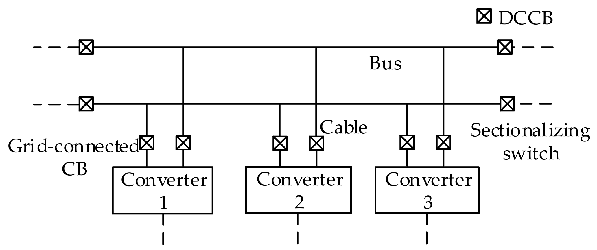
As shown in
Figure 1 [
10], equipment needing three groups of DCCBs and two groups were installed in the bus, as a result, if there are large numbers of DGs and loads, the number of the expensive DCCBs would be huge, which means much more cost [
11]. Meanwhile, when new equipment is needed to be added into a microgrid, four more CBs in the bus should be installed in bus, which is not beneficial for the system expansion and to be plug-and-play in future.
Some protection methods have been proposed for DC microgrids. In [
12], an event-based protection scheme was presented and has good performance, while, this scheme did not take characteristics of DGs into consideration. In [
13], there was a protection strategy based on the local measurement, where the coordination between converters and bus contactors is employed to limit the fault current and isolate the fault. However, the strategy was only for medium-voltage DC microgrids and could not deal with large transient resistance well. A novel unit fault detection method based superimposed current was proposed in [
14] for a single-bus DC microgrid. The method focused on cable and bus fault detection and did not involve the converters protection. In [
15,
16] protection methods for ring-bus DC microgrids are presented and both employed the conventional ring-bus structure (
Figure 2b). Two methods were mainly proposed for VSC (Voltage Source Converter), therefore, they did not completely consider other converters.
In this paper, an idea about DC microgrid structure is proposed at first, which can combine the advantages of both the conventional single bus and ring bus. Then, based on proposed structure, a protection system is designed, which includes a fast protection and a centralized pilot protection. The fast local protection is proposed for protecting the vulnerable power electronics components, which can meet speed requirements well. The pilot protection is mainly for the fault isolation, whose target is to detect and isolate the faulty zone accurately. The whole protection system is conventional for system expansion and equipment change and has great suitability for different converters.
This paper is divided into five sections.
Section 2 introduces an idea to improve the system structure. In
Section 3, local protection is illustrated, which is based on the fast fault current accumulative sum protection principle. Then, a centralized bus pilot protection strategy for isolating the faulty zone is proposed in
Section 4. Finally, based on PSCAD/EMTDC, the simulation system is established and all the methods are verified in
Section 5.
2. Structure of DC Microgrids
For the DC microgrids, the ring bus and single bus are the most common structures, whose typical structure are shown in
Figure 2 respectively [
17].
As mentioned above, the single-bus is a structure that is suitable for the control system but is not reasonable for the fault isolation, while, the ring-bus structure is opposite. The distribution grids usually have a structure of a ring-bus system and operate in single-bus state. Therefore, this idea is employed here to improve the DC microgrid.
The microgrid also has a ring-bus structure and the bus would be divided into several parts by the sectionalizing switches (SSes), which are all DCCBs. At least one SS remains open in order to avoid forming a ring electrically. An example system is presented in
Section 5. Based on such a principle, the performance of the system control and protection can be balanced.
A protection zone in this structure is defined as a part of bus between two adjacent SSes. The DCCBs for one protection zone is shown in
Figure 3. In this structure, the sectionalizing switches are not determined by operation states or equipment integration and the equipment are integrated into existing protection zones without changing the protection zones or SSes. As a result, the protection strategy based on this structure is more conventional and suitable for system expansion.
3. Local Protection Method
3.1. Protection Targets and Fault Types Classification
The protection in this section is designed for protecting the equipment instead of clearing or isolating all the faults, as a result, the protection only needs to recognize and prevent the situation that may endanger its protection object. Therefore, this protection is only employed for grid-connected CBs and not for SSes.
During a serious fault, the controllable electric electronic components can be turned off by its self-protection immediately after fault, while the uncontrollable component would continue bearing the overcurrent and they are also easily damaged [
18]. Those vulnerable devices should be the main protection objects, because only if they can avoid being damaged by faults, the converters can restart soon after fault is cleared.
Considering the damage caused by faults, the different kinds of faults have different impacts for vulnerable devices. Therefore, in this section, the faults are divided into three types, based on existing studies of DC system fault analysis.
For a grid-connected CB, a type 1 fault is the serious short-circuit faults occurring in its grid side (defined as external side), usually in a cable or bus. During such a fault, the fault characteristics are obvious, and the protection should operate in time to protect the equipment from the huge overcurrent [
19,
20]. Normally, if an external fault leading to current peak reaches once bigger than load current, it can be seen as a type 1 fault [
21].
Type 2 fault is the fault occurring inside the protection zone (defined as internal side), which means extremely short fault distance. When a type 2 fault occurs, the aim of protection is to isolate the protection range from the system immediately and satisfies that other parts of the system can operate normally [
22]. However, the damage of the protected object is hard to avoid in such a case.
The type 3 fault is the fault occurring in an external system with a far distance or large transient resistance. Unlike type 1 and 2 faults, this kind of fault does not have clear characteristics and its destructive effect is very limited [
23].
As a result, the protection does not need to operate very soon and there even may be no need to operate for a type 3 fault. Therefore, the type 3 fault should be treated differently from the type 1 and 2 faults. In this paper, the type 3 fault would be handled by the centralized pilot protection of
Section 4.
3.2. Fault Current Accumulative Sum Protection
Based on the above analysis, for the faults of type 1 or 2, it is not hard to find that the main requirements for protection are the speed and reliability. The selectivity is not that important, because the protection only needs to discover threats and isolate the protected object from the system in time and it does not need to decide the fault location.
In this section, the protection based on fault current component is employed for type 1 and 2 faults, as the fault current component can reduce the interferences from the load current. The sampling points of fault current data (
If(
k)) can be calculated as follows,
where,
I(
k) means a measurement data of current.
N is equal to
Tcfs.
Tc is calculation period.
fs is the sampling frequency of protection.
Based on the fault current calculated through Equation (1), a current accumulative sum protection method is proposed here. Compared with only adopting the fault current value directly, the accumulative sum can provide the protection with better speed and reliability. This accumulative sum current data (
Ias(
k)), can be calculated through Equation (2).
where,
N is same with that of Equation (1).
The absolute value is employed in Equation (2), because the method would deal with both the current increasing and decreasing.
Then the protection operation equation is Equation (3).
where,
N is same with that of Equation (1),
krel is the reliable coefficient and according to the existing protection experience, it can be 1.15–1.25.
kcr is the change rate coefficient. It can be seen that this operation equation means the average current variation exceeds
kcr times as large as load current during time
Tc. For improving both the reliability and sensitivity,
kcr is normally 0.4–0.6, which is sensitive enough for the type 1 and 2 faults.
For the value of Tc, this period should be short enough, because a too long calculation period cannot effectively discover the current sudden change. However, a too short period is easy to be influenced by the load current fluctuating. Normally, the Tc is 2–5 ms in DC microgrids.
The accumulative sum can accelerate the protection, which means the more serious the fault is the faster the protection acts. Meanwhile, the method has a dynamic threshold, as a result, there is no conventional setting value. Therefore, the protection suitability is improved, and complicated setting calculation is avoided.
4. Centralized Pilot Protection
The task of this protection is to detect and isolate the faulty zone and adjust the conditions of SSes after the fault is cleared. The pilot protection is employed here. A centralized protection also can be combined with proposed structure well, because the centralized protection possesses an obvious advantage of protecting the system from global perspective.
4.1. System Modeling
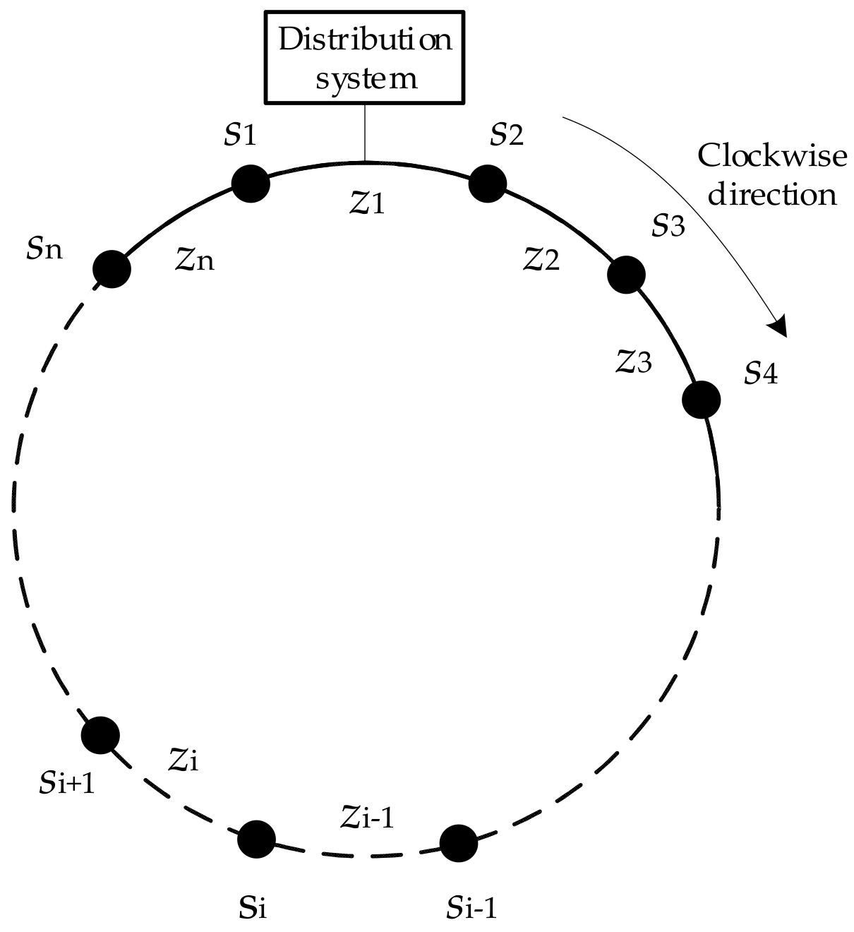
The topological information is the foundation for this centralized protection scheme, so it is necessary to number the protection zones and sectionalize switches at first.
The protection zone, which is connected with distribution system directly, is numbered as z1, and other zones should be named as z2 to zn successively in a clockwise direction.
For the sectionalizing switches, their current positive direction is also defined as clockwise direction. Their numbers are same with the adjacent protection zones located at their positive direction and are named as
s1,
s2,
s3…
sn. This system modeling method is illustrated in
Figure 4.
Besides, based on the numbers and current positive direction of positive pole, it is easy to create a current direction incidence matrix (matrix
A). In this matrix, there are relations between the protection zones and current of their adjacent SSes. The forming principle of the matrix
A is shown in Equation (4)
Matrix A is shown in Equation (5).
4.2. Directional Element and Direction Information
The fault current direction information of the whole bus is necessary, so every position where SSes are installed should be a measurement point. For improving the protection reliability and sensitivity, all the directional elements include two parts, which are the starting element and the fault direction measurement element.
Based on the positive direction, the direction principle of fault current component is not hard to be established. For the positive pole, the positive fault current component means the positive fault. While, it is opposite for the negative pole. As a result, faulty pole selection is necessary for the directional element.
4.2.1. Directional Element for Grid-Connected CBs
For the grid-connected CBs, their directional elements are mainly based on the local protection of
Section 3. Both the starting and fault direction are calculated through the fault current component. Their positive direction is defined as internal side and the microgrid side is the negative direction.
Those directional elements only send an internal fault message to the information center and block itself when there is a positive fault. They do not send any messages when there are external faults. A workflow for this directional element is shown in
Figure 5.
Where, ifp and ifn are fault current component of positive and negative pole respectively, which are both calculated through Equation (1). iasp and iasn are accumulative sum current from the positive and negative poles respectively, which are both calculated through Equation (2). It can be seen that this workflow has included the starting element, faulty pole selection, and direction measurement.
4.2.2. Starting Elements for the SSes
Unlike the local protection which only needs to deal with the dangers for the protected object, the pilot bus protection should be able to deal with all the faults, even the faults with very small fault current.
In addition, the pole-to-pole fault and pole-to-ground fault have different characteristics. The pole-to-pole faults are usually metallic and easy to be discovered, while, when it comes to the pole-to ground-fault, they are usually the type 3 faults because of large transient resistance.
In this section, the starting elements have two algorithms of parallelism for two different faults and these are transverse differential algorithm and fault overcurrent algorithm.
Transverse differential current algorithm is proposed to deal with the pole-to-ground faults. The transverse differential current (
itd) is calculated through Equation (6)
where the
ip and
in are measurement current from the positive pole and negative pole respectively.
Based on the
itd, the pole-to-ground fault is easy to be discovered and the relative equation is Equation (7).
where,
is also a reliable coefficient, which can be 1.15–1.25, according to the engineering experience;
kun is the unbalance current coefficient and its value can be 0.1–0.2, according to allowed maximum unbalance load current of a system.
iN is the nominal bus current.
The fault overcurrent algorithm is for the pole-to-pole fault, which is very simple and shown as follows.
where,
is same with that of Equation (7).
kf is the fault current coefficient and can be 1.2–1.5. The
if is fault current component and calculated through Equation (1).
The protection adopts the transient currents, which only occur when there are short-circuit faults, as a result, the normal load current fluctuating is not a threat anymore and protection has enough reliability itself. Therefore, the threshold can be properly declined to improve the protection sensitivity, which means the setting coefficient (kun, kf) can be a little smaller.
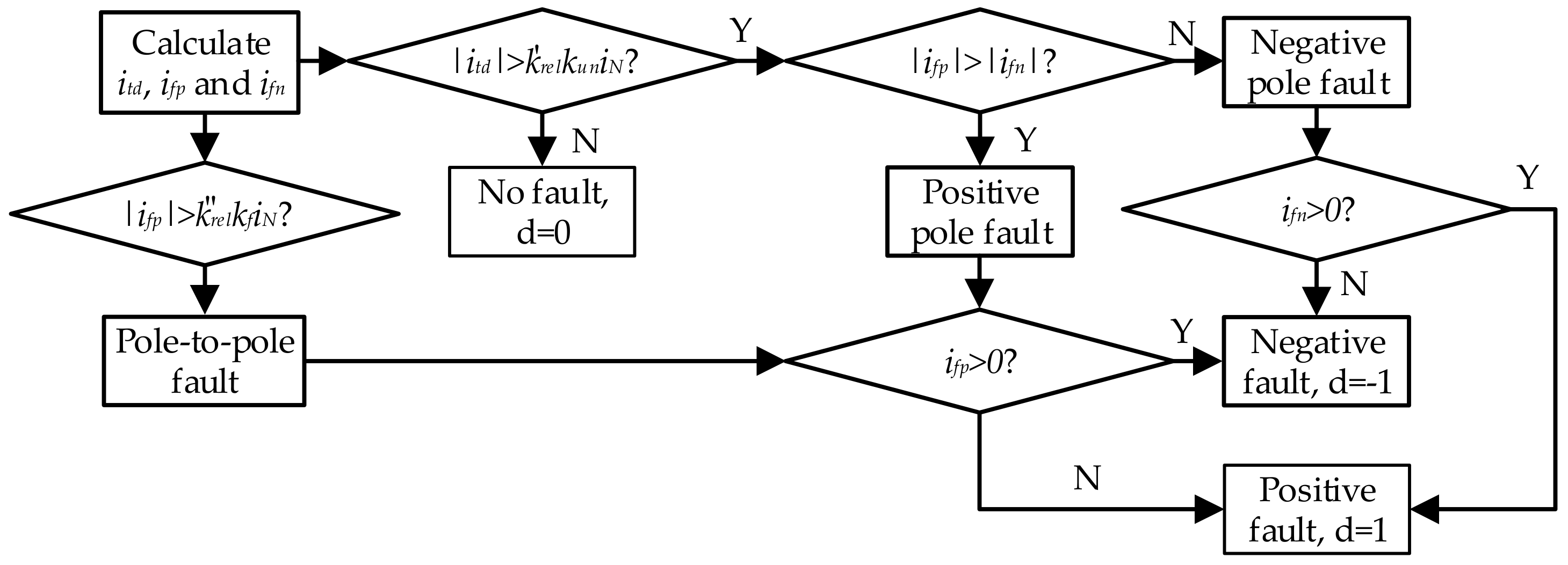
4.2.3. Direction Measurement Principle for the SSes
After the starting conditions are satisfied, the directional element would start. For the pole-to-pole fault, the first task of directional element is to find the faulty pole, because Equation (8) is only able to discover the fault. As the unfaulty pole current changes much less than that of faulty pole at the beginning of a fault, the faulty pole can be selected through Equation (9).
where,
ifp and
ifn are the same with that of
Figure 5.
If Equation (9) is satisfied, there is a positive pole fault and if not, the fault is negative pole pole-to-ground fault.
The direction data should be digital. In this paper, 1 is for the positive fault and −1 is for the negative fault. A 0 means the starting conditions are not satisfied and this data is set by the information center.
The complete workflow of this directional element is shown in
Figure 6.
4.3. Pilot Protection Algorithms
If the message sending conditions are satisfied, the direction information would be sent to the information center. After receiving the first direction information, the pilot protection starts, and the information center should wait for time
td to receive all the information. The
td can be determined by Equation (10)
The tdmin and tdmax are the maximum and minimum normal delay time of communication system respectively. However, the directional elements of the open SSes would not suffer any overcurrent; so, the information center should have a proper method for that condition.
At first, if the information center receives the internal fault message, the information center should send closing signals for all the equipment to recover the supply, while the blocked grid-connected CBs could not be closed by this signal.
If information center does not receive the block signal, the protection should calculate a result array to discover the fault zone further and direction array D is the foundation here.
In
D, there are data for the direction information from the SSes, and
Ds is shown in Equation (11)
where, the
d1,
d2…
dn means the direction information from the
s1,
s2…
sn respectively.
Then, a correcting matrix (matrix
C) is proposed and the elements in correcting matrix can be created according to Equation (12).
The correcting direction array (
), is produced through Equation (13).
Therefore, the final result array
R can be obtained.
If the element ri in R satisfies ri > 1, the zi is the faulty zone.
The whole pilot protection flowchart is in
Figure 7.
For the whole process, its main operation time is taken by
and the simple calculation process only needs several milliseconds [
24].
mainly depends on the communicated method and system size [
25], which also can be less than 0.03 s for a microgrid, relying on existing technologies [
26]. Therefore, the unfaulty equipment can restart in less than 0.05 s.
6. Conclusions
In this paper, a complete protection system is established for an improved structure for DC microgrids. The main conclusions and shortages are as follows:
(1) In the future, there may be a large number of DGs and loads in a DC microgrid. This paper aims at proposing the structure and protection methods for such a system.
(2) The local protection and centralized pilot protection are responsible for the protection speed and selectivity respectively; as a result, both requirements can be satisfied.
(3) Some conventional overcurrent or inverse-time overcurrent backup protection can be adopted to avoid the possible load overcurrent for the converters, and it is not involved in this paper because of limited space.
(4) For recovering the whole system as soon as possible, distinguishing the transient fault and permanent fault is a very helpful way and this part can be researched in further studies.


