Article

Numerical Analysis of Roadway Rock-Burst Hazard under Superposed Dynamic and Static Loads

1
State Key Laboratory of Mining Disaster Prevention and Control, Shandong University of Science and Technology, Qingdao 266590, China
2
State Key Laboratory for Geomechanics and Deep Underground Engineering, China University of Mining and Technology, Beijing 100083, China
*
Author to whom correspondence should be addressed.
Energies 2019, 12(19), 3761; https://doi.org/10.3390/en12193761
Submission received: 10 September 2019 / Revised: 27 September 2019 / Accepted: 30 September 2019 / Published: 30 September 2019
(This article belongs to the Special Issue Advanced Technologies for Energy Exploitation of Coals)

Abstract

:
Microseismic events commonly occur during the excavation of long wall panels and often cause rock-burst accidents when the roadway is influenced by dynamic loads. In this paper, the Fast Lagrangian Analysis of Continua in 3-Dimensions (FLAC3D) software is used to study the deformation and rock-burst potential of roadways under different dynamic and static loads. The results show that the larger the dynamic load is, the greater the increase in the deformation of the roadway under the same static loading conditions. A roadway under a high static load is more susceptible to deformation and instability when affected by dynamic loads. Under different static loading conditions, the dynamic responses of the roadway abutment stress distribution are different. When the roadway is shallow buried and the dynamic load is small, the stress and elastic energy density of the coal body in the area of the peak abutment stress after the dynamic load are greater than the static calculations. The dynamic load provides energy storage for the coal body in the area of the peak abutment stress. When the roadway is deep, a small dynamic load can still cause the stress in the coal body and the elastic energy density to decrease in the area of the peak abutment stress, and a rock-burst is more likely to occur in a deep mine roadway with a combination of a high static load and a weak dynamic load. When the dynamic load is large, the peak abutment stress decreases greatly after the dynamic loading, and under the same dynamic loading conditions, the greater the depth the roadway is, the greater the elastic energy released by the dynamic load. Control measures are discussed for different dynamic and static load sources of rock-burst accidents. The results provide a reference for the control of rock-burst disasters under dynamic loads.

1. Introduction

The sudden release of the elastic energy accumulated in an ore body around a mining working is likely to induce a rock-burst accident [1]. Resulting in coal and rock being thrown onto the roadway accompanied by loud sounds, and they cause vibrations and damage to the coal and rock mass, damage to brackets and equipment, casualties, and severe deformation of roadways [2,3]. With the increasing demand for and production of coal, the depth of coal mines is increasing, and rock-burst disasters are becoming increasingly serious. In China, there have been more than 170 pairs mines have a rock-burst potential, in which more than 4000 rock-burst accidents have occurred, causing hundreds of casualties and damaging more than 30 kilometers of roadways [4].
Based on the different types of loading, rock-bursts can be divided into static loading rock-bursts and dynamic loading rock-bursts [5]. With an increase in the depth of a coal seam, the initial ground stress increases gradually, and geological structures such as faults and folds are more widely distributed. Areas near the synclinal axes of folds and reverse faults are often areas of high stress in which large amounts of elastic energy accumulate, and the excavation of a panel leads to a greater stress concentration during the redistribution of the mining stress [6,7,8]. When the dynamic stress of the stope exceeds the strength of the coal and the rock mass, a rock-burst failure of the coal body occurs suddenly [9,10,11]. The source of energy for static loading rock-burst accidents is the stress concentration near the mining workings. The occurrence of a dynamic loading-induced rock-burst is closely related to roof breakage, fault slip, blasting and other dynamic load sources. When vibration waves caused by roof breakage, fault slip, blasting and other mining activities affect the coal and rock mass near the mining working, the vibration waves cause the additional dynamic loads in the coal and rock mass; in severe cases, the sudden instability of the coal and rock mass will lead to a rock-burst accident [12,13,14]. Numerous field measurements have shown that a high dynamic load will cause a more severe rock-burst accident and greater damage to the rock surrounding the roadway [15,16].
The coal seam in Panel 8935 of the Xinzhou Yao Coal Mine is only at the depth of 250 m. The immediate roof is composed of 0–3.26 m of gray-white fine sandstone, the main roof is composed of 27.67–35.71 m of gray-white siltstone, and the Protodyakonov coefficient of the gray-white siltstone is 8–16. The mine has typical hard roof conditions, and many rock-burst accidents occur during mining. Zhao et al. [17] conducted a statistical analysis of the rock-burst accidents and microseismic events that occurred during mining of Panel 8935. The microseismic events with energy levels greater than 104 J during the mining process are mainly distributed in the hard roof rock layer within 50 m in advance of the working face. The maximum microseismic event energy is 6 × 10⁷ J. The rock-burst accidents mainly caused by the microseismic event are triggered by the breaking of the hard roof. The vibration wave propagates to the area where the stress is concentrated, causing a sudden release of elastic energy, which causes a rock-burst accident. Even if the panel is relatively shallow and the initial stress is small, because the energy level of the microseismic event is large and the microseismic event occurs very close to the mining working, the potential for a rock-burst due to the strong dynamic load is still high with a low static load.
Panel 25110 of the Yuejin Coal Mine is oriented in the strike direction of the F16 reverse fault. The dip of the F16 reverse fault is approximately 75°, the displacement is 50–500 m, and the length is 45 km. The depth of Panel 25110 is 800–1200 m, the immediate roof is composed of an 18-m-thick layer of mudstone, and the main roof is composed of a 190-m-thick layer of hard gravel [18,19]. The severity of the rock-bursts during mining of the panel is significantly greater than that during roadway excavation. The occurrence of rock-bursts is mostly related to high-energy microseismic events. The high-energy microseismic events that occur during excavation of the roadway mainly have energies of 105–106 J, and those that occur during mining of the panel are mainly concentrated at 107–108 J. On August 11, 2010, a significant rock-burst accident occurred during the mining of Panel 25110. A total of 362.8 m of the roadway was seriously damaged, and the energy of the burst source was 9 × 10⁷ J. The damage to the roadway caused by the rock-burst is shown in Figure 1. This rock-burst accident was mainly due to the large, thick and hard rock layer with high strength and good integrity, which is difficult to make fall after the coal seam is recovered. Panel 25110 is deeply buried, and the structural stress in the fault area is high. Mining the panel results in a high stress concentration of the coal mass in front of the working face. The sudden fracturing of the thick and hard roof and fault activation can cause a high-energy seismic event. The superposition of the high static load and the high dynamic load was the main reason for the serious rock-burst accident.
The rock-burst is caused by the sudden release of a large amount of elastic energy stored in the rock mass, so the rock-burst accident is more likely to occur in the high-stress coal or rock mass. However, the accumulation of a large amount of elastic energy in the coal or rock mass is only a precondition for the occurrence of rock-burst. The disturbance of the external dynamic load may be one of the key factors triggering the occurrence of rock-burst [2]. Therefore, high stress areas have higher rock-burst potential. However, the accumulation of a large amount of elastic energy in a high stress area of a rock mass is only one prerequisite for the occurrence of a rock-burst; an external dynamic load disturbance is also a key factor causing a rock-burst. Therefore, studying the roadway deformation and the rock-burst potential under different superposed dynamic and static loads can increase the understanding of the mechanism of rock-bursts and the choice of control technology. By considering the influences of the roadway excavation area, support mode and rock mass characteristics, numerical simulations have become one of the main means to study roadway stability and rock-burst potential [20,21,22,23]. In this paper, the FLAC3D numerical simulation software is used to study the deformation process and rock-burst potential of the roadway due to the superposition of different static and dynamic loads. The results can provide guidance for the assessment of the roadway rock-burst potential and the control of rock-bursts induced by dynamic loads.

2. Model Description

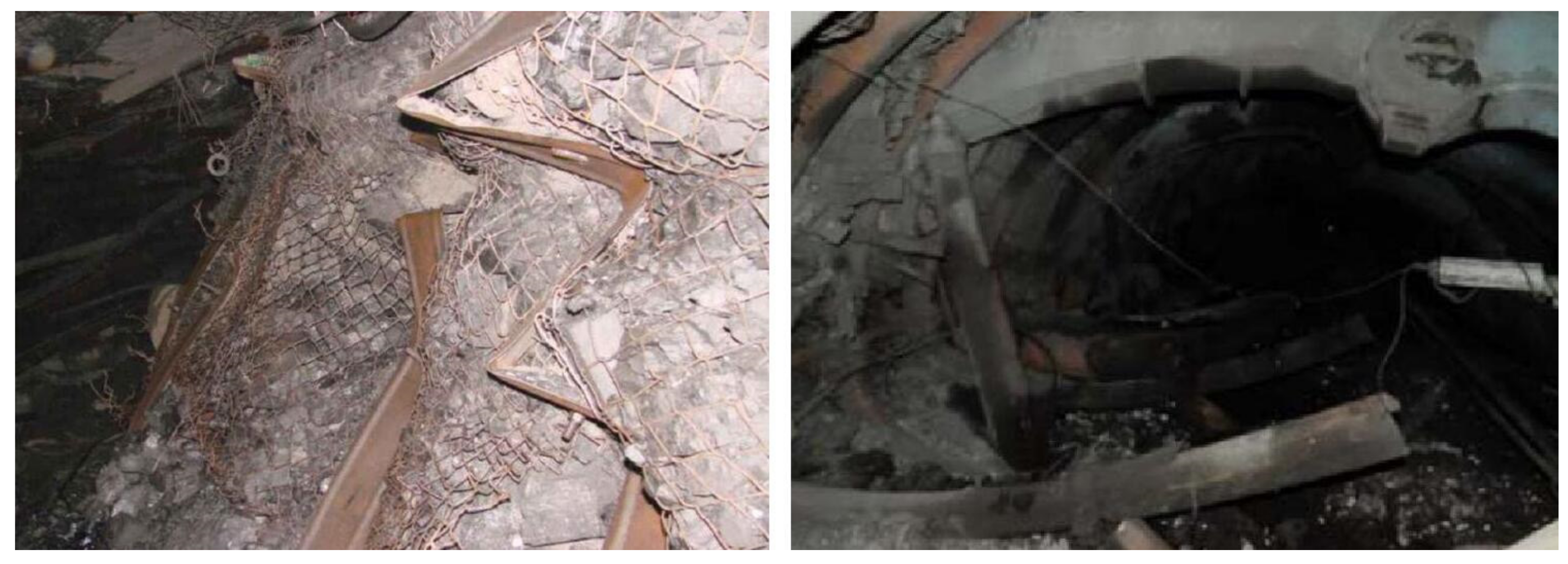
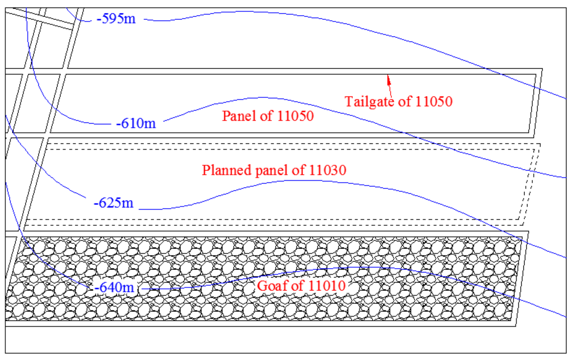
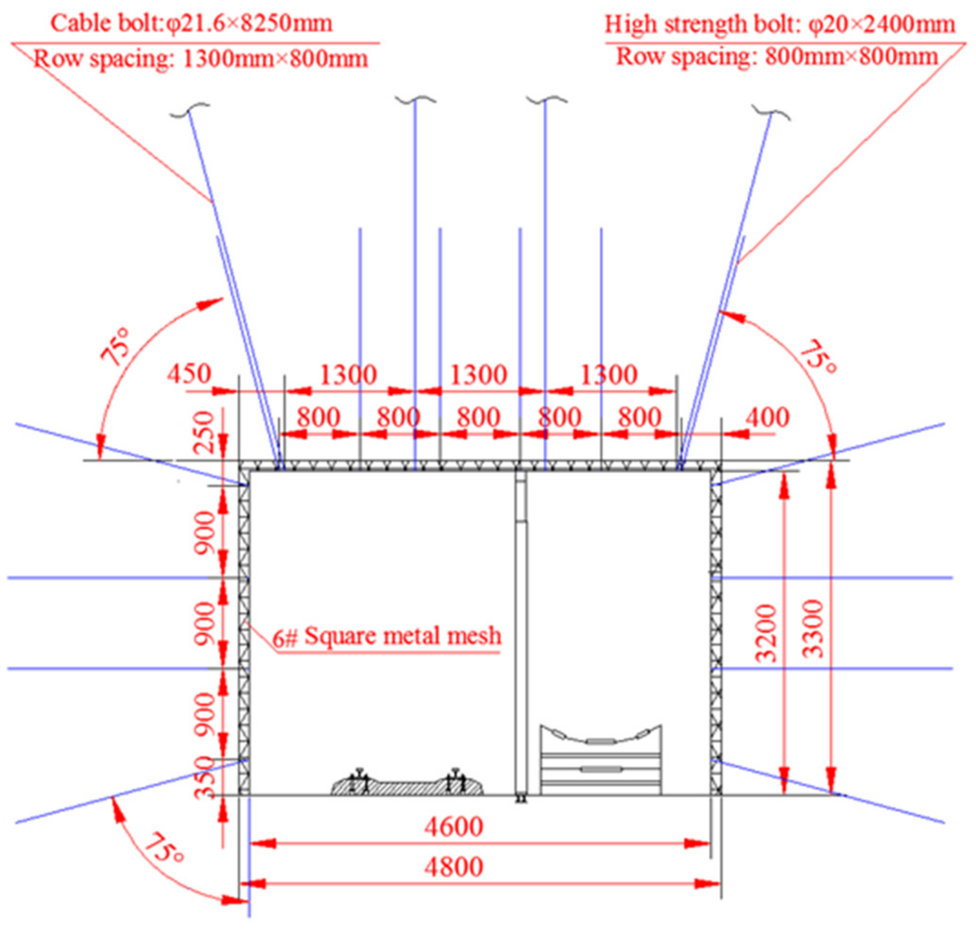
2.1. General Engineering Geology Conditions

The research object is Zhaogu No. 2 Coal Mine, which is located in Xinxiang City, Henan Province, China. The area is flat, and the mining is performed using comprehensive mechanized coal mining technology. The panel adopts the retreat longwall mining method to extract the coal seam, and use caving method for the goaf without backfill. The coal seam is 5.2–6.6 m thick with an average thickness of 6.2 m. It has a simple structure and is a nearly horizontal, stable and thick coal seam [21,24].
This paper focuses on the tailgate of Panel 11050 in the Zhaogu No. 2 Coal Mine. Panel 11050 is 600 m deep (the blue line in Figure 2 is the contour of the coal seam floor), 180 m wide, and the strike length is 2000 m, as shown in Figure 2. When the Panel 11010 extracted step by step, form a void (goaf) behind the work face, rocks fall from the roof and fill the goaf. However, the goaf of the Panel 11010 is far from the tailgate of Panel 11050, and the Panel 11010 has little effect on the tailgate of Panel 11050. The tailgate of Panel 11050 is driven along the roof of the coal seam. The cross-section of the roadway is rectangular, the roadway is 4.8 m wide and 3.3 m high. The support design scheme is shown in Figure 3. The rebar bolts have a length of 2.4 m, a diameter of 20 mm and a spacing of 800 mm × 800 mm. The cable bolts have a length of 8.25 m, a diameter of 21.6 mm and a spacing of 800 × 1300 mm. The anchor lengths of the anchor and the anchor cable are 1200 mm and 2400 mm, respectively.

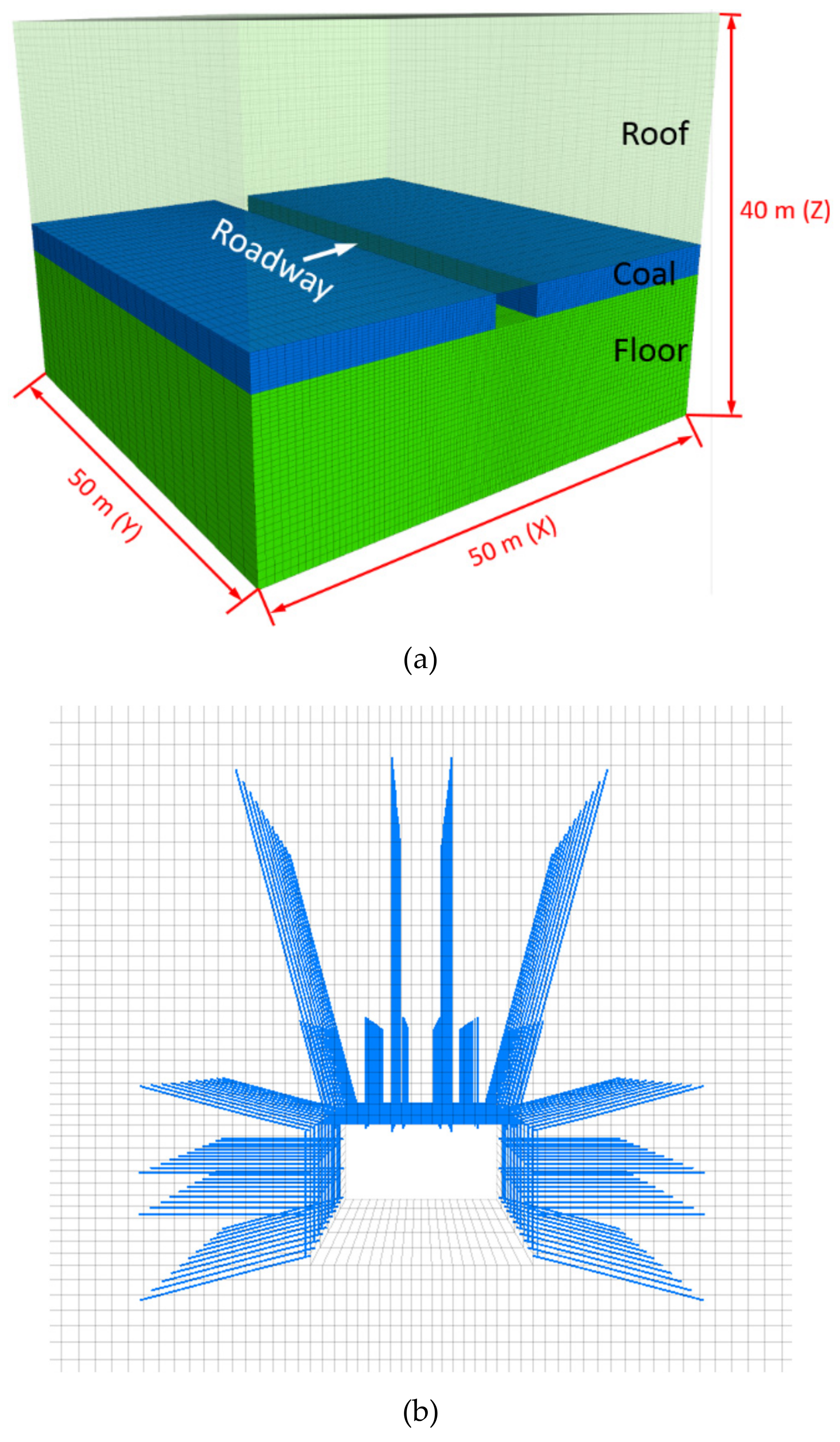
2.2. Development of Numerical Models

A numerical simulation model of the tailgate of Panel 11050 is established based on its geological profile. The model is 50 m long, 50 m wide and 40 m high, as shown in Figure 4a. During the roadway excavation and coal extraction of the Panel 11050, micro-seismic events will occur due to roof breaking or structural plane slip induced by mining. The dynamic load will cause the roadway deformation and rock-burst potential to increase. This paper mainly simulates the deformation and rock-burst potential of roadways under different superposed dynamic and static lodes. To reduce the impact of the rock structure on the simulation results, the structure of the strata around the roadway is simplified; the roadway is excavated in the coal seam, the roof is composed of mudstone, the floor is composed of sandstone, and no coal is left behind on the top and bottom. The displacement of the side boundary of the numerical model is fixed. The mechanical parameters of the rock mass (Table 1) are estimated based on the complete rock characteristics and the generalized Hoek-Brown failure criterion. The mechanical parameters of intact rock are determined in the laboratory [24]. A strain-softening constitutive model based on the Mohr-Coulomb criterion is adopted, and Figure 1 shows the rock mass parameters [24,25,26]. The cable bolts and steel bolts are regarded as structural elements. This type of element is embedded in FLAC3D to simulate the roadway support. The support form of the roadway is shown in Figure 4b, and Table 2 gives the parameter values of various abutment structural elements.

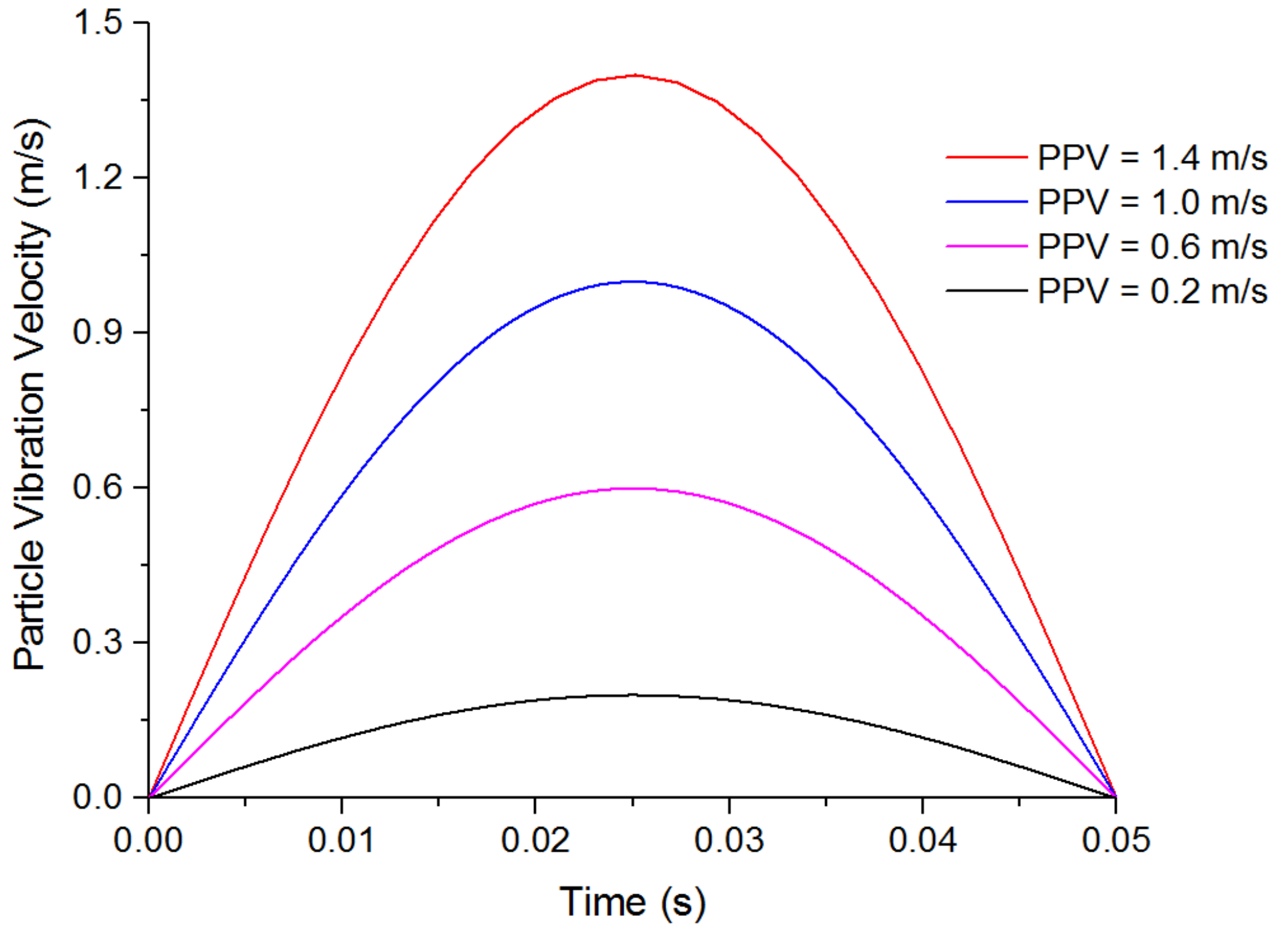
2.3. Simulation Methodology

Rock-bursts are closely related to mining depth, and mining depth is one of the main geological factors affecting rock-bursts. Statistical analysis shows that the possibility of a rock-burst increases with an increase in the mining depth. To study the deformation characteristics of the roadway under different superposed dynamic and static loads, the initial vertical stress is set to 10 MPa, 20 MPa and 30 MPa, and the corresponding depths of the coal seam are 400 m, 800 m and 1200 m, respectively, if we assume that the bulk density is 25 kN/m3. The horizontal-to-vertical stress ratios σx, σy are 1.2 and 0.8, respectively, based on a study carried out at a nearby mine.
The propagation of a seismic wave excites the particle velocity of the rock mass, and there is a strong correlation between the particle velocity and damage to the rock mass. A high-energy microseismic event will generate a high particle vibration velocity in the coal and rock mass near the mining working, which in serious cases will cause a rock-burst accident. Mutke et al. [27,28] using the velocity sensors, combined with the near-field peak particle velocity (PPV) empirical formula induced by the microseismic event in the Upper Sicilian Coal Mine, the PPV of the rock-burst position is measured and calculated. Statistical analysis of 120 rock-burst accidents during the period from 1988 to 2006 in the Upper Sicilian Coal Mine showed that 90% of the rock-burst accidents were induced by seismic events, and the PPVs values in the areas where the rock-bursts occurred were mainly concentrated in the range of 0.05 m/s to 1.0 m/s. Table 3 lists the effects of seismicity on the rock-burst potential. Therefore, four gradients of 0.2 m/s, 0.6 m/s, 1.0 m/s and 1.4 m/s are selected to simulate dynamic loads of different magnitudes. The waveforms of the four dynamic loads are shown in Figure 5. The vibration is a semisine wave, the frequency is 20 Hz, and the vibration time is that for one cycle [29,30,31,32]. Wu et al. [33] analyzed the rock-burst potential of roadway under different buried depth conditions. The hazard level of roadway depth and rock-burst potential is shown in Table 3. However, the current prediction and evaluation of rock-burst potential are independently studied from the two aspects of dynamic and static load. Therefore, it is meaningful to study the rock-burst potential under different superposed dynamic and static loads
During the static analysis, the boundary of the model is fixed. For the dynamic analysis, the boundary conditions of the model become viscous to prevent the model boundary from reflecting seismic waves. The numerical simulation process is shown in Figure 6. The viscous boundary condition is based on the use of independent buffers (mechanical viscous dampers) in the normal and shear directions of the model boundary to effectively absorb the energy of the seismic waves, especially when the incident angle is greater than 30° [34]. Local damping is selected as the form of damping. The damping ratio of the rock is between 2% and 5%; therefore, 5% local damping is used in this study [35,36].

3. Distribution Characteristics of the Deformation and Plastic Zone under Different Loads

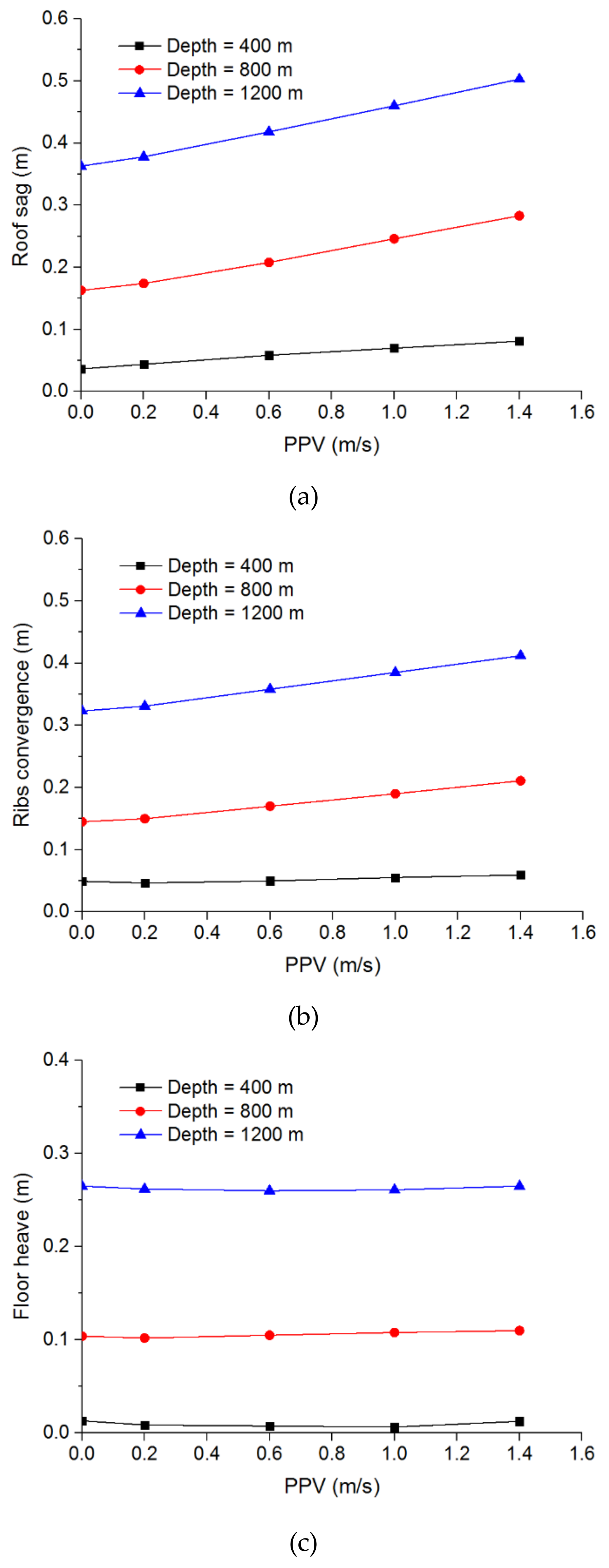
3.1. Deformation of the Roadway under Different Superposed Dynamic and Static Loads

Figure 7 shows the deformation of the roadway under different superposed dynamic and static loads, in which Figure 7a–c show the roof sag, the rib convergence and the floor heave, respectively. According to Figure 7a, when the PPV is 0 m/s (i.e., no dynamic load is applied) and the depths of the roadway are 400 m, 800 m and 1200 m, the roof sags are 0.037 m, 0.163 m and 0.363 m, respectively. When different dynamic loads are applied to the roadway, the deformation of the roadway increased to different degrees. Under the same static load, the larger the dynamic load is, the greater the increase in roof sag. Under the influence of the dynamic load, the roof sags of the roadway with different static loads show different variations; the greater the static load is, the greater the influence of the dynamic load is. When the PPV is 1.4 m/s, the roof sag of the roadway with a depth of 400 m increases by 0.044 m from 0.037 m to 0.081 m after the dynamic load. The roof sag of the roadway at 800 m depth increases by 0.12 m from 0.163 m to 0.283 m, and the roof sag of the roadway with a depth of 1200 m increases by 0.14 m from 0.363 m to 0.503 m. Therefore, the influence of the dynamic load on the roadway deformation is significantly lower when the static load is low, and the dynamic load of a roadway with a high static load is more likely to cause large deformation and even a rock-burst accident. Figure 7b shows that the rib convergence of the roadway is very similar to that of the roof sag under different superposed dynamic and static loading conditions, but under the same dynamic load, the rib convergence is slightly less than the roof sag. In contrast to the variations in the roof sag and the rib convergence, the floor heave of the roadway changes little when the dynamic load is applied to the top surface of the model. The main reason is that refractions and reflections occur when the vibration wave is transferred to the surface of the rock surrounding the roadway, resulting in a sharp decrease in the vibration wave transmitted to the floor, so the increase in the deformation of the roadway floor after the dynamic load is small.

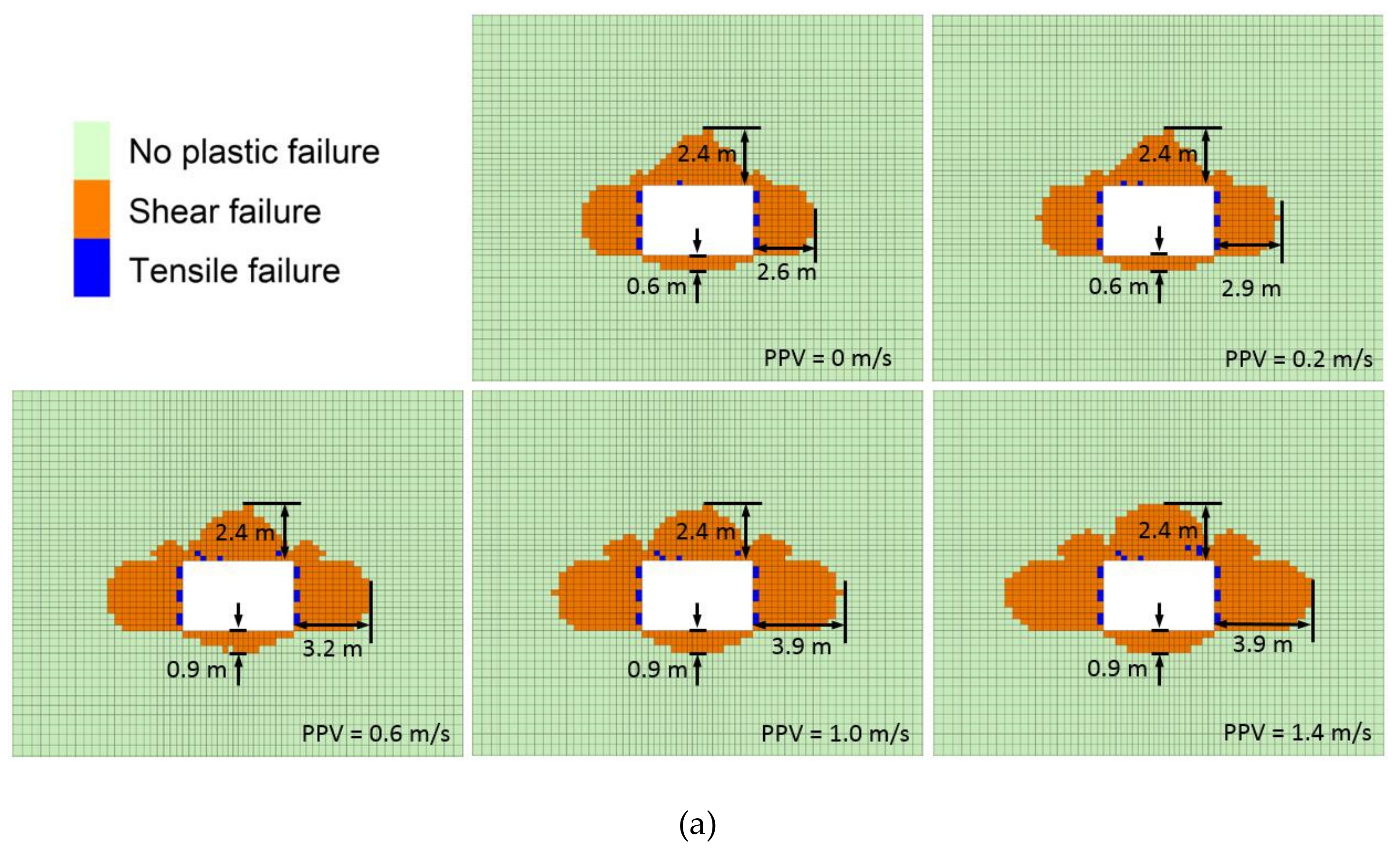
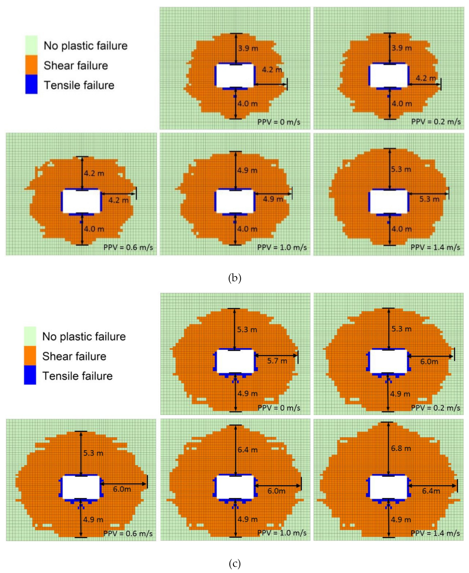
3.2. Distribution of the Plastic Zone of the Roadway under Different Superposed Dynamic and Static Loads

Figure 8 shows the variations in the plastic zone of the roadway under different superposed dynamic and static loads. The results show that the greater the depth of the roadway is, the wider the plastic zone in the surrounding rock is after the static calculation. Figure 8 shows that the areas of the plastic zones around the roadways with different depths affected by different dynamic loads expand to varying degrees. When the PPV is less than or equal to 0.2 m/s, the dynamic load has little effect on the area of the plastic zone, and the number of elements in the plastic zone increases only slightly. When the PPV is greater than or equal to 0.6 m/s, the area of the plastic zone is larger than that in the static calculation, especially when the depth of the roadway is 800 m, and the number of units in the plastic zone increases most significantly. When the depth of the roadway is 400 m, the number of units in the plastic zone increases the least. Figure 8a shows that when the depth of the roadway is 400 m, the plastic zone around the roof and the two ribs is large, and that around the roadway floor is small. After the dynamic load, the area of the plastic zone on both sides increases, and the areas of the plastic zones around the roof and floor increase slowly. When the PPVs are 0 m/s, 0.2 m/s, 0.6 m/s, 1.0 m/s and 1.4 m/s, the plastic zones around the roadway have areas of 2.6 m, 2.9 m, 3.2 m, 3.9 m and 4.2 m, respectively. When the PPV is 0.2 m/s, the plastic zone is very small due to the small dynamic load. When the depth of the roadway is 800 m, the area of the plastic zone around the floor after the static calculation is 4 m, which is greater than that when the depth of the roadway is 400 m. After the dynamic load, the area of the plastic zone around the roof and two ribs is obviously larger, and that of the floor is nearly unchanged. When the depth of the roadway is 1200 m, the variation in the plastic area under different dynamic and static loading conditions is similar to that when the depth is 800 m. However, a comparison of Figure 8b,c show that when the depth of the roadway is 1200 m, the increase in the plastic area under the same dynamic load is less than that for the roadway depth of 800 m. When the roadway is buried at 1200 m, the plastic area after the static calculation extends 5.7 m from the free surface of the roadway. The ultimate strength of the coal body in the triaxial stress state is high because of the high confining pressure, so it is difficult to expand the plastic zone in the surrounding rock after the dynamic load.

4. Rock-burst Risk Analysis under Different Superposed Dynamic and Static Loads

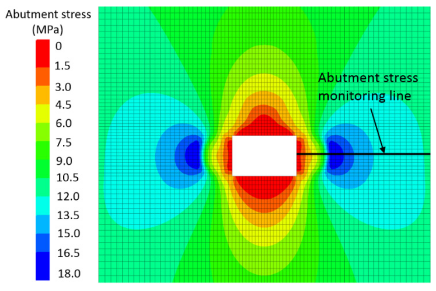
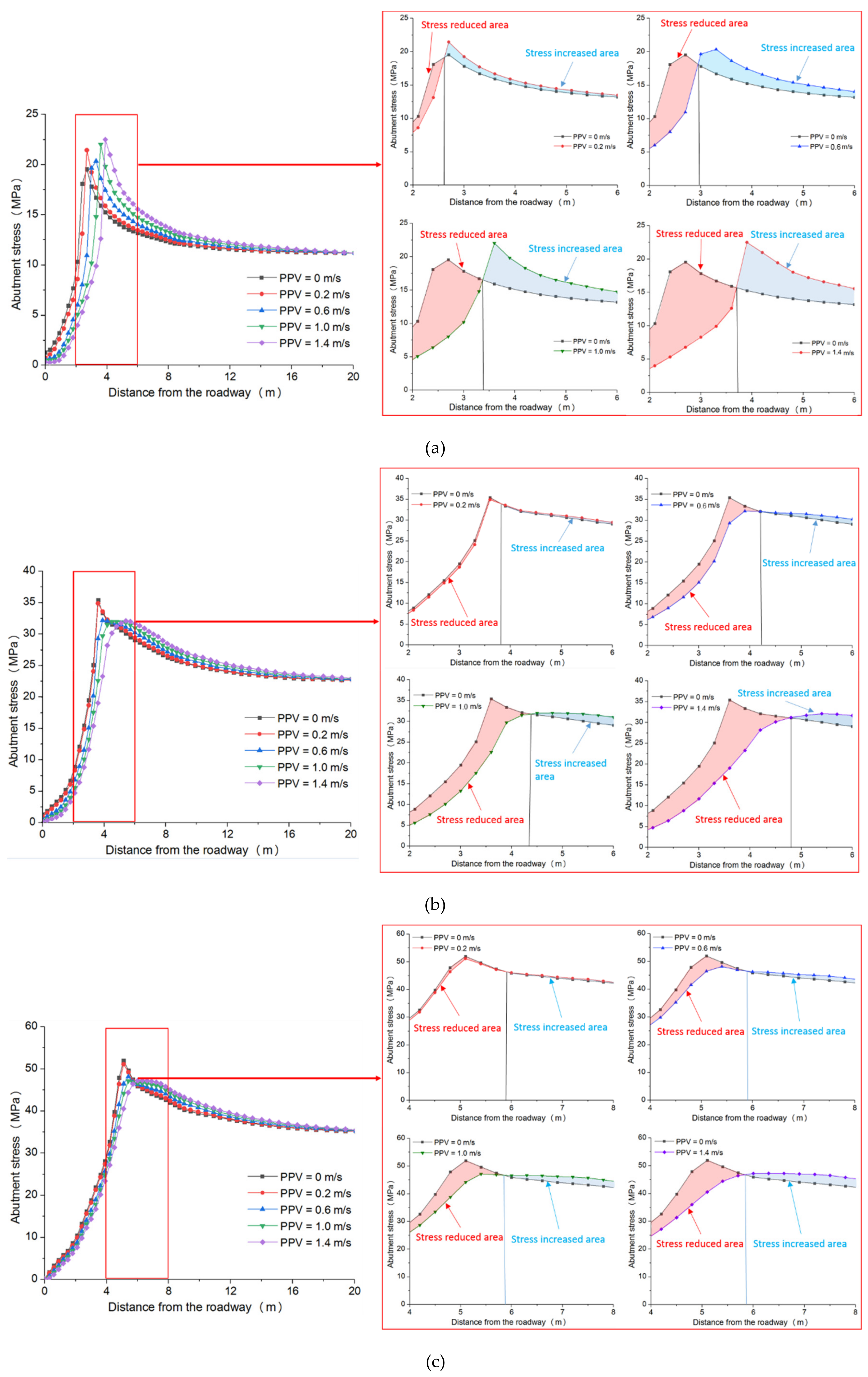
4.1. Variation in the Abutment Stress under Different Superposed Dynamic and Static Loads

The position of the measuring point of the abutment stress is shown in Figure 9. Figure 10 shows the variations in the abutment stress under different superposed dynamic and static loads. Figure 10a–c show the variations in the abutment stress under different dynamic loads at depths of 400 m, 800 m and 1200 m, respectively. The position of the measuring point of the abutment stress is shown in Figure 9. A comparison of Figure 10a–c shows that as the depth of the roadway increases, the peak value of the roadway abutment stress after the static calculation increases, and the peak value of the abutment stress continuously shifts to the position of the coal body far from the rib. When the depths of the roadway are 400 m, 800 m and 1200 m, the peak values of the abutment stress are 19.6 MPa, 35.4 MPa and 51.95 MPa, respectively, and the distances from the roadway rib are 2.6 m, 3.6 m and 5.1 m, respectively. A comparison with the area of the plastic zone in Figure 8 shows that the peak abutment stress is located at the position of the elastoplastic boundary in the coal body. Figure 10a shows that when the depth of the roadway is 400 m and the dynamic load PPV is 0.2 m/s, the variation in the abutment stress is small after the dynamic load, and the dynamic load has different effects on the stress in the coal body in different regions. The vibration of the coal body less than 2.5 m from the roadway is reduced by the dynamic load. The stress in the coal body at distances greater than 2.5 m from the roadway is higher after the dynamic load, and the dynamic load causes the stress in the coal body at the position of the peak abutment stress to increase. After the dynamic load, the peak value of the supporting stress increases from 19.6 MPa to 21.4 MPa. The dynamic load first causes the stress in the plastic failure zone of the coal body to decrease. The small dynamic load (PPV < 0.2 m/s) does not cause plastic damage to the coal body in the region of the peak abutment stress, and the stress in the peak stress region maintains the state of energy storage. A comparison of the variation in the abutment stress under different dynamic loads in the red frame on the right side of Figure 10a shows that with a gradual increase in the PPV, the area of reduced abutment stress after the dynamic load also increases; at PPVs of 0.6 m/s, 1.0 m/s and 1.4 m/s, the greatest distances of the region of reduced support stress from the rib of the roadway are 2.8 m, 3.4 m and 3.7 m, respectively. These results show that the dynamic load has an increasing influence on the supporting stress with increasing dynamic load. Moreover, when the dynamic load is greater than or equal to 0.6 m/s, the coal body in the area of the peak abutment stress with the static load is seriously damaged by the dynamic load, and the stress is significantly reduced. The magnitude of the stress reduction is greater than in the coal body near the roadway, indicating that the elastic energy of the coal near the elastoplastic boundary of the peak stress region is one of the main energy sources for the rock-burst. The elastic energy that accumulates in the coal at this location is released suddenly due to the disturbance of the dynamic load, and the rock-burst potential is significantly increased.
Figure 10b shows the changes in the bearing stress under different dynamic loading conditions when the roadway depth is 800 m. When the PPV is 0.2 m/s, the maximum distance between the area of reduced abutment stress and the rib of the roadway is 3.7 m. The peak abutment stress after the static calculation is 35.4 MPa, and the stress decreases after the dynamic load to 34.9 MPa. Therefore, under a high static load, a low dynamic load can still cause the peak abutment stress in the coal body to decrease. Therefore, the probability of a rock-burst induced by the superposition of a high static load and a weak dynamic load is greater in a deep roadway. The area in which the abutment stress is reduced and the decrease in the abutment stress are greater than with a roadway depth of 400 m, and the larger the dynamic load is, the larger the area and the greater the decrease in the support stress are. Figure 10c shows the changes in the abutment stress under different static loads when the roadway depth is 1200 m. A comparison of Figure 10b with Figure 11c shows that when the roadway depth is 1200 m, the influence of the dynamic load on the abutment stress of the roadway is essentially the same, but the range of variation of the abutment stress under the same dynamic load is slightly different. When the roadway depth is 1200 m, the reduction in the peak abutment stress is slightly smaller than when the roadway depth is 800 m. When the tunnel is buried at a depth of 1200 m, the dynamic load has little effect on the size of the plastic zone. Therefore, the position of the peak abutment stress does not change substantially under different dynamic loads, but the decrease in stress in the region of reduced stress still increases with increasing dynamic load.

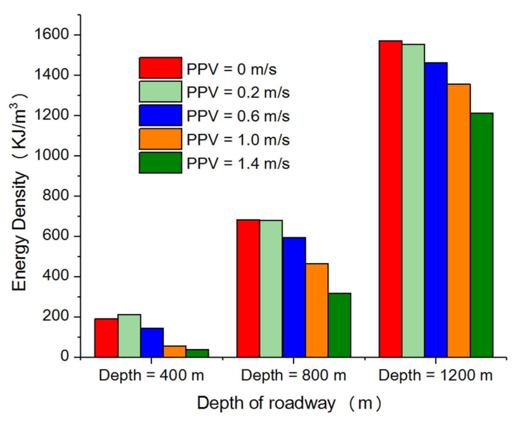
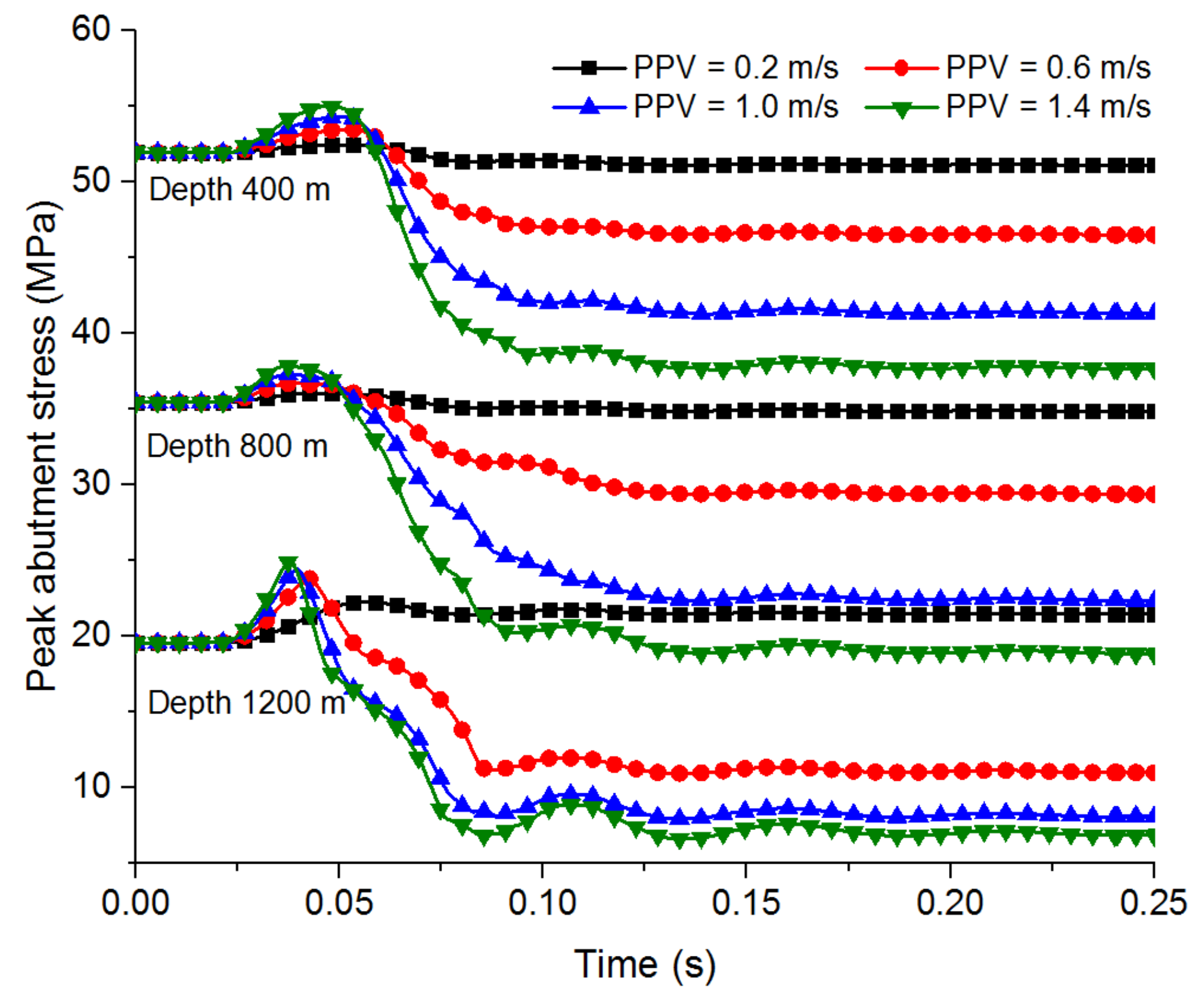
4.2. Variations in the Peak Abutment Stress and Elastic Energy Density under Different Superposed Dynamic and Static Loads
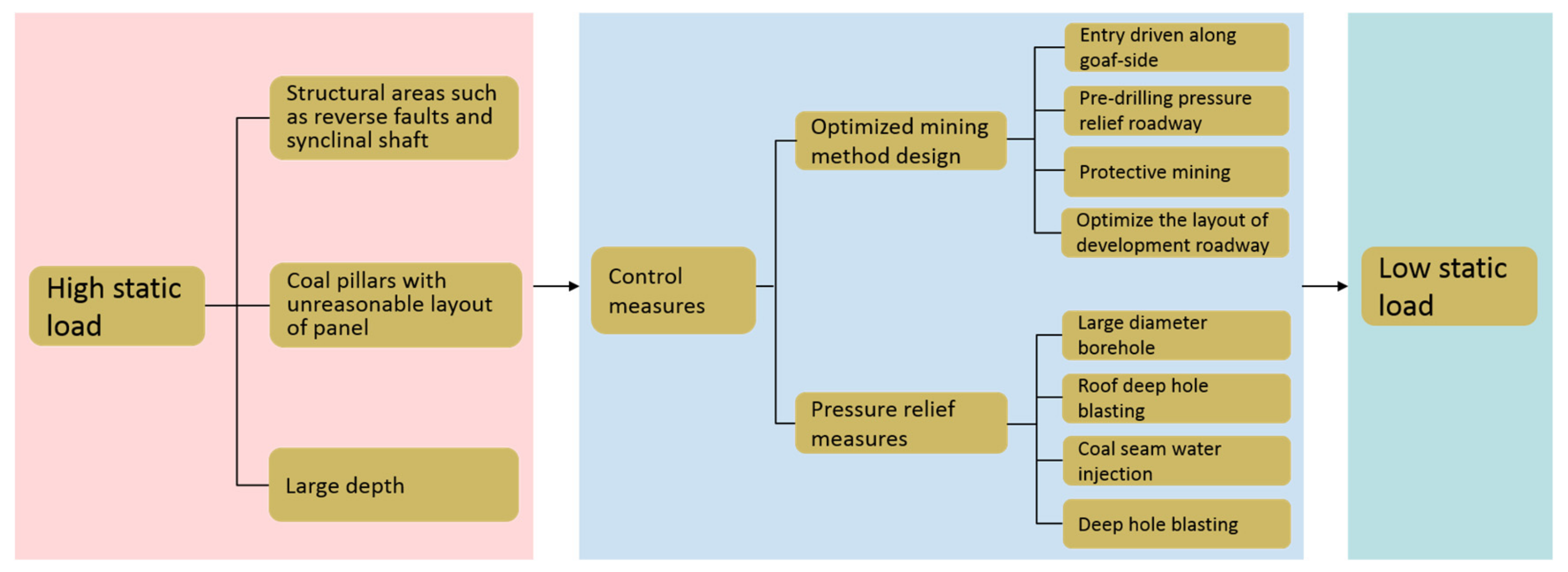
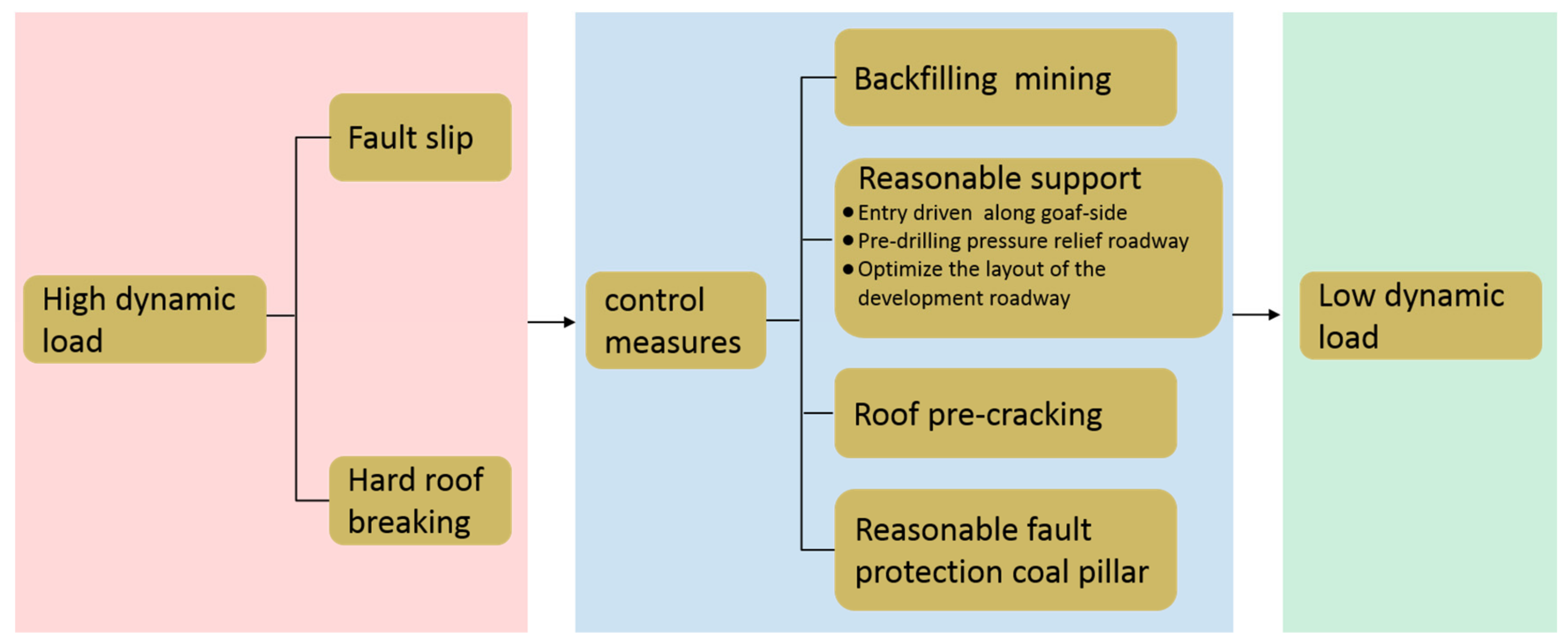
Studies have shown that the sudden release of elastic energy is often caused by the dynamic load, which can induce rock-burst accidents. Therefore, this section monitors the coal body in the region of the abutment stress under the dynamic load and studies the influence of the dynamic load on the peak abutment stress in the coal. The FISH language embedded in FLAC3D is used to program the strain energy density in the area of the peak abutment stress. The variation in the coal energy density in the area of the peak abutment stress under different superposed dynamic and static loads is studied. The strain energy density in the coal body in the area of the peak abutment stress (i.e., the strain energy of a unit body under a three-dimensional stress) is:
U e = 1 2 E [ σ 1 2 + σ 2 2 + σ 3 2 2 v ( σ 1 σ 2 + σ 2 σ 3 + σ 1 σ 3 ) ]
where σ1, σ2, and σ3 are the maximum, intermediate, and minimum principal stresses of the unit in the numerical model, respectively, and E and ν are the elastic modulus and Poisson’s ratio of the surrounding rock, respectively.
Figure 11 shows the elastic energy density of the coal body in the area of the peak abutment stress under different superposed dynamic and static loads, and Figure 12 shows the variations in the stress in the coal body in the area of the peak abutment stress under different dynamic loads. Figure 12a shows that when the depth of the panel is 400 m and the PPV is 0.2 m/s, the vibration wave is transmitted to the region of the peak abutment stress, and the abutment stress gradually increases. As the vibration wave gradually subsides, the abutment stress gradually decreases, and the stress then goes down slightly and eventually stabilizes at 21.4 MPa, which is higher than the 19.6 MPa after the static calculation. The energy density of the coal body in the area of the peak abutment stress increases from 192.7 kJ/m3 to 213.4 kJ/m3, and the dynamic load provides energy storage for the coal body at the peak abutment stress. When the dynamic load is greater than or equal to 0.6 m/s, the vibration wave is transmitted to the area of the peak abutment stress, causing a significant increase in the stress of the coal body; the greater the PPV is, the greater the magnitude of the stress increase is. After the stress reaches the maximum value, a significant drop occurs, and the higher the PPV is, the faster the decrease is, and the lower the stress after the dynamic load is. When the dynamic load PPVs are 0.6 m/s, 1.0 m/s and 1.4 m/s, the stress values after the dynamic load are 11.0 MPa, 8.02 MPa and 6.77 MPa, respectively, the energy densities are 145.4 kJ/m3, 56.9 kJ/m3 and 38.6 kJ/m3, respectively, and the peak stress and elastic energy density are less than those in the static calculation. These results show that the dynamic load causes the coal body to be damaged in the area of the peak abutment stress; that the larger the dynamic load is, the greater the coal body damage is; and that the dynamic load induces a sudden release of elastic energy in the stress concentration area, which can easily cause a rock-burst accident. When the depth of the roadway is 800 m, the peak abutment stress after the static calculation is 35.4 MPa. When the PPV is 0.2 m/s, the peak abutment stress after the dynamic load is 34.9 MPa, which is slightly lower than the abutment stress after the static load. Moreover, Figure 12 shows that the PPV of 0.2 m/s causes a small amount of elastic energy to be released in the roadway at a depth of 800 m. The elastic energy density decreases from 684.9 kJ/m3 to 680.3 kJ/m3. When the PPVs are 0.6 m/s, 1.0 m/s and 1.4 m/s, the stress values after the dynamic load are reduced to 29.3 MPa, 22.3 MPa and 18.7 MPa, respectively, and the elastic energy density decreases to 597.3 kJ/m3, 466.5 kJ/m3 and 319.9 kJ/m3, respectively; the stresses and elastic energy densities are significantly lower than the static calculations. When the PPV is greater than 0.6 m/s, the coal body releases a large amount of elastic energy after the dynamic load. When the roadway depth is 1200 m, the influence of the dynamic load on the peak abutment stress of the roadway is similar to that of the roadway with a depth of 800 m. However, the peak abutment stress and the elastic energy density after the dynamic load are slightly less than with the roadway depth of 800 m. Although the magnitude of the peak abutment stress and the elastic energy density decrease slightly less than with the roadway depth of 800 m, the area where the abutment stress and the elastic energy density are reduced is much larger than with the roadway depth of 800 m. Therefore, the total energy released by the 1200-m-deep roadway after the dynamic load is still greater than that with the 800-m-deep roadway.

5. Discussion

A rock-burst of a roadway due to a dynamic disturbance is a mechanical failure process under the influence of static and dynamic loads accompanied by energy consumption, release and conversion. When the roadway is shallow and the dynamic load is small (depth of 400 m, PPV of 0.2 m/s), only the coal body near the roadway’s contour will be subjected to a stress reduction and elastic energy release after the dynamic load. The coal body far from the roadway is in a triaxial stress state due to the high confining pressure, and the bearing capacity of the coal body increases. The small dynamic load cannot cause plastic failure of the coal body at this position, and no elastic energy is released. Further damage to the coal in the plastic zone leads to increases in the stress and the elastic energy of the coal in the elastoplastic boundary area. When the depth of the roadway is 400 m and the PPV is greater than or equal to 0.6 m/s, the dynamic load causes the coal body in the area of high confining pressure to undergo plastic failure, the stress and the elastic energy density decrease sharply, and the dynamic load causes an increase in the rock-burst potential because of the release of the elastic energy of the coal body. When the depth of the roadway is 800 m, due to the increase in the static stress, a small dynamic load (PPV of 0.2 m/s) can cause decreases in the stress and elastic energy density of the coal body at the peak abutment stress; therefore, it is more prone to rock-bursts due to the high static load and low dynamic load. When the dynamic load is greater than or equal to 0.6 m/s, the reductions in the stress and elastic energy density of the coal body in the area of the peak abutment stress under the same dynamic loading conditions are much greater than with the roadway depth of 400 m. Therefore, a roadway at a large depth has a greater rock-burst potential under the same dynamic load than a shallower roadway.
Since the dynamic and static load sources that induce the rock-burst are different, corresponding control measures should be proposed for the specific load source. The results of Chapter 5 show that the high static load is more susceptible to the dynamic load and the energy released is much greater than the low static load. Therefore, taking appropriate measures to reduce the stress concentration of the coal body can effectively reduce the rock-burst potential. The pressure relief measures generally adopted for high static loads are: large diameter borehole pressure relief, coal seam water injection, deep hole blasting, etc., [37]. Mines with shallow depths generally have a small initial stress, but there may be large tectonic stresses in structural areas such as reverse faults and synclinal shaft. If the panel is not rationally arranged in the shallow coal seam, a large number of coal pillars are left, the mining activity may cause a significant increase in the static load of the coal pillar area, so the mining working also has a high rock-burst potential. Therefore, a reasonable arrangement of the panel avoids the occurrence of residual coal pillars that can effectively control the occurrence of rock-burst [38,39]. Figure 13 shows the high static load source and control measures.
The main sources of dynamic load during mine excavation are hard roof breaking and fault slip. The prevention and control of dynamic load induced rock-burst should focus on reducing the possibility of occurrence of large energy seismic events. For the dynamic load source of the roof breaking, the roof pre-cracking method can be used to reduce the breaking distance of the roof, thereby reducing the dynamic load released by the hard roof breaking. Backfilling mining methods can also be used to control the extent of roof fracture to ensure the stability of the hard roof and to control fault slip. Figure 14 shows the high dynamic load source and control measures. The fault slip load source can control the fault slip by using the fault coal pillar method with appropriate size. Generally speaking, a reasonable support system is the last line of defense against the occurrence of rock-burst. One of the critical considerations for rock-burst support is to ensure that the support systems can accommodate the levels of energy release in a coal burst. A constant-resistance large-deformation anchor (cable) capable of providing constant resistance and good elongation can reduce the rock-burst potential under the control of dynamic load. In addition, in order to ensure the stability of the roadway, the strength and distance of the advanced support should be strengthened [40,41,42,43].

6. Conclusions

Based on the engineering background of the 11050 roadway in the Zhaogu No. 2 Mine, this paper uses the FLAC3D numerical simulation software to study the roadway deformation, the distributions of the abutment stress and the changes in the elastic energy density under different dynamic and static loading conditions. In addition, the rock-burst potential of the roadway under different dynamic and static loading conditions is analyzed. The results show that when the dynamic load PPV is less than or equal to 0.2 m/s, the increase value of the roadway deformation is small, and when the dynamic load is greater than or equal to 0.6 m/s, the deformation of the roadway increases significantly due to the dynamic load. Moreover, the amount of roof sag and ribs convergence are larger, and the value of the Floor heave is smaller. Under the same static load, the larger the dynamic load is, the greater the increase in the roadway deformation is, so a roadway with a high static load is more prone to deformation and instability.
The distribution of the abutment stress in roadways is greatly affected by the dynamic loads. Based on the variation in the abutment stress before and after the dynamic loads, the abutment stress can be divided into areas of increasing stress and areas of decreasing stress. Under the same static loading conditions, the larger the dynamic load is, the larger the area of stress reduction is, and the greater the stress reduction is. If the dynamic load causes the coal body in the area of the peak abutment stress to have a significant plastic failure, the elastic energy that has accumulated in the stress concentration region may be released suddenly due to the dynamic load, and a rock-burst accident is likely to occur.
The dynamic responses of the roadway abutment stress distribution under different depth conditions are different. When the roadway is shallow and the dynamic load is small (e.g., depth of 400 m, PPV of 0.2 m/s), the stress and elastic energy density of the coal body in the area of the peak abutment stress increase after the dynamic loading. When the dynamic load is large (e.g., PPV greater than or equal to 0.6 m/s), the peak abutment stress decreases greatly after the dynamic load with the roadway depth of 400 m, and the elastic energy in the coal body in the area of the peak abutment stress is released. Therefore, a roadway under a weak static load and strong dynamic load still has a high rock-burst potential. When the depth of the roadway is large (e.g., greater than or equal to 800 m), a small dynamic load (PPV less than or equal to 0.2 m/s) can still cause the stress and elastic energy density of the coal body in the area of the peak abutment stress to decrease. Therefore, it is highly probable that a high static load and a weak dynamic load will cause a rock-burst accident in a deep mine roadway. Under the same dynamic loading conditions, the greater the depth of the roadway, the greater the elastic energy released by the dynamic load.
The prevention and control of rock-bursts should be based on the specific dynamic and static load sources. For rock-bursts induced by high static loads, pressure relief measures (such as large diameter borehole pressure relief, coal seam water injection, etc,.) should be used to reduce the stress concentration in the coal and rock mass. For rock-bursts induced by strong dynamic loads, measures (such as roof pre-cracking, backfilling mining, etc.) should be taken to reduce the occurrence of high-energy seismic events. For rock-bursts induced by the superposition of dynamic and static loads, appropriate measures should be taken to reduce the occurrence of high-energy seismic events and at the same time, pressure relief measures are taken to reduce the stress concentration of coal and rock mass.

Author Contributions

Methodology, P.K., L.J., J.J.; software, P.K.,Y.W; validation, L.C., J.N.; investigation, L.J., J.J.; resources, L.C., J.N.; data curation, P.K., L.J.; writing—original draft preparation, P.K., J.J.; writing—review and editing, L.J., visualization, Y.W., L.J., J.J.; funding acquisition, L.J.

Funding

The research for this study was sponsored by the National Natural Science Foundation of China (Grant No. 51704182), the Natural Science Foundation of Shandong Province (ZR2017BEE050), China Postdoctoral Science Foundation funded project (2019M652436) and the Graduate Innovation Fund of Shandong University of Science and Technology (SDKDYC190344)

Conflicts of Interest

The authors declare no conflict of interest.

References

  1. Whyatt, J.K.; Blake, W.; Williams, T.J.; White, B.G. 60 years of rockbursting in the Coeur D’ Alene District of northeastern Idaho, USA: lessons learned and remaining issues. In Proceedings of the 109th Annual Exhibit and Meeting, Society for Mining, Metallurgy, and Exploration, Phoenix, AZ, USA, 25–27 February 2002; pp. 1–10. [Google Scholar]
  2. Zhu, W.C.; Li, Z.H.; Zhu, L.; Tang, C.A. Numerical simulation on rockburst of underground opening triggered by dynamic disturbance. Tunn. Undergr. Space Technol. 2010, 25, 587–599. [Google Scholar] [CrossRef]
  3. Kong, P.; Jiang, L.; Shu, J.; Wang, L. Mining Stress Distribution and Fault-Slip Behavior: A Case Study of Fault-Influenced Longwall Coal Mining. Energies 2019, 12, 2494. [Google Scholar] [CrossRef]
  4. Wang, G.F.; Gong, S.Y.; Dou, L.M.; Cai, W.; Yuan, X.Y.; Fan, C.J. Rockburst mechanism and control in coal seam with both syncline and hard strata. Saf. Sci. 2019, 115, 320–328. [Google Scholar] [CrossRef]
  5. Wang, L.H.; Cao, A.Y.; Dou, L.M.; Guo, W.H.; Zhang, Z.Y.; Zhi, S.; Zhao, Y.X. Numerical simulation on failure effect of mining-induced dynamic loading and its influential factors. Saf. Sci. 2019, 113, 372–381. [Google Scholar] [CrossRef]
  6. Shepherd, J.; Rixon, L.K.; Griffiths, L. Outbursts and geological structures in coal mines: A review. Int. J. Rock Mech. Min. Sci. Géoméch. Abstr. 1981, 18, 267–283. [Google Scholar] [CrossRef]
  7. Li, Z.; Dou, L.; Cai, W.; Wang, G.; He, J.; Gong, S.; Ding, Y. Investigation and analysis of the rock burst mechanism induced within fault–pillars. Int. J. Rock Mech. Min. Sci. 2014, 70, 192–200. [Google Scholar] [CrossRef]
  8. Wang, Z.; Li, L. Study of Energy Release in Failure of Coal and Rock Near Fault on ANSYS. Geotech. Geol. Eng. 2019, 37, 2577–2589. [Google Scholar] [CrossRef]
  9. Chen, S.J.; Yin, D.W.; Jiang, N.; Wang, F.; Guo, W.J. Simulation study on effects of loading rate on uniaxial compression failure of composite rock-coal layer. Geomech. Eng. 2019, 17, 333–342. [Google Scholar]
  10. Li, Y.; Zhang, S.; Zhang, X. Classification and fractal characteristics of coal rock fragments under uniaxial cyclic loading conditions. Arab. J. Geosci. 2018, 11, 201. [Google Scholar] [CrossRef]
  11. Shen, W.L.; Bai, J.B.; Li, W.F.; Wang, X.Y. Prediction of relative displacement for entry roof with weak plane under the effect of mining abutment stress. Tunn. Undergr. Space Technol. 2018, 71, 309–317. [Google Scholar] [CrossRef]
  12. Jiang, L.; Wu, Q.S.; Wu, Q.L.; Wang, P.; Xue, Y.; Kong, P.; Gong, B. Fracture failure analysis of hard and thick key layer and its dynamic response characteristics. Eng. Fail. Anal. 2019, 98, 118–130. [Google Scholar] [CrossRef]
  13. Wang, J.; Ning, J.G.; Qiu, P.Q.; Yang, S.; Shang, H.F. Microseismic monitoring and its precursory parameter of hard roof collapse in longwall faces: A case study. Geomech. Eng. 2019, 17, 375–383. [Google Scholar]
  14. Sainoki, A.; Mitri, H.S. Simulating intense shock pulses due to asperities during fault-slip. J. Appl. Geophys. 2014, 103, 71–81. [Google Scholar] [CrossRef]
  15. Ortlepp, W.D.; Stacey, T.R. Rockburst mechanisms in tunnels and shafts. Tunn. Undergr. Space Technol. 1994, 9, 59–65. [Google Scholar] [CrossRef]
  16. Hossein, H.; Felix, H.; Catherine, A.; Stefan, B. Migration-based microseismic event location in the schlema-alberoda mining area. Int. J. Rock Mech. Min. 2018, 110, 161–167. [Google Scholar]
  17. Zhao, Y.X.; Jiang, Y.D.; Wang, T.; Gao, F.; Xie, S.T. Features of microseismic events and precursors of rock-burst in underground coal mining with hard roof. J. China Coal Soc. 2012, 37, 1960–1966. [Google Scholar]
  18. Li, Z.L.; Dou, L.M.; Cai, W.; Wang, G.F.; Ding, Y.L.; Kong, Y. Roadway stagger layout for effective control of gob-side rock-bursts in the longwall mining of a thick coal seam. Rock Mech. Rock Eng. 2016, 49, 621–629. [Google Scholar] [CrossRef]
  19. Cai, W. Fault Rockburst Induced by Static and Dynamic Loads Superposition and Its Monitoring and Warning. Ph.D. Thesis, China University of Mining and Technology, Xuzhou, China, 2015. [Google Scholar]
  20. Kong, P.; Jiang, L.; Shu, J.; Sainoki, A.; Wang, Q. Effect of Fracture Heterogeneity on Rock Mass Stability in a Highly Heterogeneous Underground Roadway. Rock Mech. Rock Eng. 2019, 1–18. [Google Scholar] [CrossRef]
  21. Jiang, L.S.; Kong, P.; Shu, J.M.; Fan, K. Numerical Analysis of Support Designs Based on a Case Study of a Longwall Entry. Rock Mech. Rock Eng. 2019, 1–12. [Google Scholar] [CrossRef]
  22. Shu, J.; Jiang, L.; Kong, P.; Wang, P.; Zhang, P. Numerical Modeling Approach on Mining-Induced Strata Structural Behavior by Considering the Fracture-Weakening Effect on Rock Mass. Appl. Sci. 2019, 9, 1832. [Google Scholar] [CrossRef]
  23. Oggeri, C.; Ova, G. Quality in tunnelling: ITA-AITES Working Group 16 Final report. Tunn. Undergr. Space Technol. Inc. Trenchless Technol. Res. 2004, 19, 239–272. [Google Scholar] [CrossRef]
  24. Jiang, L.; Sainoki, A.; Mitri, H.S.; Ma, N.; Liu, H.; Hao, Z. Influence of fracture-induced weakening on coal mine gateroad stability. Int. J. Rock Mech. Min. Sci. 2016, 88, 307–317. [Google Scholar] [CrossRef]
  25. Yan, S.; Bai, J.; Wang, X.; Huo, L. An innovative approach for gateroad layout in highly gassy longwall top coal caving. Int. J. Rock Mech. Min. Sci. 2013, 59, 33–41. [Google Scholar] [CrossRef]
  26. Zhang, G.; Wen, Z.; Liang, S.; Wu, Y.; Zhou, H. S Ground Response of a Gob-side Entry in a Longwall Panel Extracting 17m-thick Coal Seam: A case study. Rock Mech. Rock Eng. 2019. [Google Scholar] [CrossRef]
  27. Mutke, G.; Dubiński, J.; Lurka, A. New criteria to assess seismic and rock-burst hazard in coal mines. Arch. Min. Sci. 2015, 60, 743–760. [Google Scholar]
  28. Mutke, G.; Lurka, A.; Dubiński, J. Seismic monitoring and rock burst hazard assessment in Deep Polish Coal Mines–Case study of rock burst on April 16, 2008 in Wujek-Slask Coal Mine. In 7th International Symposium on Rockburst and Seismicity in Mines (RASiM 7): Controlling Seismic Hazard and Sustainable Development of Deep Mines, January, 2009; Tang, C.A., Ed.; Rinton Press: Paramus, NJ, USA, 2009; pp. 1413–1424. [Google Scholar]
  29. Wang, X.; Cai, M. Numerical modeling of seismic wave propagation and ground motion in underground mines. Tunn. Undergr. Space Technol. 2017, 68, 211–230. [Google Scholar] [CrossRef]
  30. Mortazavi, A.; Alavi, F.T. A numerical study of the behavior of fully grouted rockbolts under dynamic loading. Soil Dyn. Earthq. Eng. 2013, 54, 66–72. [Google Scholar] [CrossRef]
  31. He, J.; Dou, L.M.; Cai, W.; Li, Z.L.; Ding, Y.L. In Situ Test Study of Characteristics of Coal Mining Dynamic Load. Shock. Vib. 2015, 2015, 1–8. [Google Scholar] [CrossRef] [Green Version]
  32. Li, Y.C.; Sun, S.Y.; Tang, C.A. Analytical Prediction of the Shear Behaviour of Rock Joints with Quantified Waviness and Unevenness Through Wavelet Analysis. Rock Mech. Rock Eng. 2019, 1–13. [Google Scholar] [CrossRef]
  33. Wu, S.; Wu, Z.; Zhang, C. Rock burst prediction probability model based on case analysis. Tunn. Undergr. Space Technol. 2019, 93, 103069. [Google Scholar] [CrossRef]
  34. Itasca. FLAC3D-Fast Lagrangian Analysis of Continua; Itasca Consulting Group Inc.: Minneapolis, MN, USA, 2009. [Google Scholar]
  35. Sainoki, A.; Mitri, H.S. Influence of mining activities on the reactivation of a footwall fault. Arab. J. Geosci. 2017, 10, 99. [Google Scholar] [CrossRef]
  36. ABAQUS. ABAQUS Online Documentation: Ver 6.4-1; Dassault Systemes: Vélizy-Villacoublay, France, 2003. [Google Scholar]
  37. Wei, C.; Zhang, C.; Canbulat, I.; Cao, A.; Dou, L. Evaluation of current coal burst control techniques and development of a coal burst management framework. Tunn. Undergr. Space Technol. 2018, 81, 129–143. [Google Scholar] [CrossRef]
  38. Wu, Q.H.; Weng, L.; Zhao, Y.L.; Guo, B.H.; Luo, T. On the tensile mechanical characteristics of fine-grained granite after heating/cooling treatments with different cooling rates. Eng. Geol. 2019, 253, 94–110. [Google Scholar] [CrossRef]
  39. Zhang, Z.; Yu, X.; Wu, H.; Deng, M. Stability Control for Gob-Side Entry Retaining with Supercritical Retained Entry Width in Thick Coal Seam Longwall Mining. Energies 2019, 12, 1375. [Google Scholar] [CrossRef]
  40. Kaiser, P.K.; Cai, M. Design of rock support system under rockburst condition. J. Rock Mech. Geotech. Eng. 2012, 4, 215–227. [Google Scholar] [CrossRef] [Green Version]
  41. Fu, M.X.; Liu, S.W.; Jia, H.S.; He, D.Y. Experimental study of an orientation and resin-lifting device for improving the performance of resin-anchored roof bolts. Rock Mech. Rock Eng. 2019. [Google Scholar] [CrossRef]
  42. Wu, Q.H.; Li, X.B.; Weng, L.; Li, Q.; Zhu, Y.; Luo, R. Experimental investigation of the dynamic response of prestressed rockbolt by using an SHPB-based rockbolt test system. Tunn. Undergr. Space Technol. 2019, 93, 103088. [Google Scholar] [CrossRef]
  43. Wu, Y.; Hao, Y.; Tao, J.; Teng, Y.; Dong, X. Non-destructive testing on anchorage quality of hollow grouted rock bolt for application in tunneling, lessons learned from their uses in coal mines. Tunn. Undergr. Space Technol. 2019, 93, 103094. [Google Scholar] [CrossRef]
Figure 1. Damage to the roadway caused by a rock-burst.
Energies 12 03761 g001
Figure 2. The plan view of the panel layout.
Energies 12 03761 g002
Figure 3. Gateroad support design.
Energies 12 03761 g003
Figure 4. Numerical model. (a) Model size, (b) Roadway support.
Energies 12 03761 g004
Figure 5. Waveforms of four different dynamic loads.
Energies 12 03761 g005
Figure 6. Flow chart of the numerical simulation calculation.
Energies 12 03761 g006
Figure 7. Deformation of the roadway under different superposed dynamic and static loads. (a) Roof sag under different superposed dynamic and static loads, (b) Ribs convergence under different superposed dynamic and static loads and (c) Floor heave under different superposed dynamic and static loads.
Energies 12 03761 g007
Figure 8. Plastic zone of the roadway under different superposed dynamic and static loads. (a) Plastic zone when the roadway is 400 m deep, (b) plastic zone when the roadway is 800 m deep and (c) plastic zone when the roadway is 1200 m deep.
Energies 12 03761 g008aEnergies 12 03761 g008b
Figure 9. Abutment stress monitoring position (the roadway depth is 400 m).
Energies 12 03761 g009
Figure 10. Variations of the roadway abutment stress under different superposed dynamic and static loads. (a) Variations of the roadway abutment stress when the roadway depth is 400 m, (b) Variations of the roadway abutment stress when the roadway depth is 800 m and (c) Variations of the roadway abutment stress when the roadway depth is 1200 m.
Energies 12 03761 g010
Figure 11. Variations in the elastic energy density in the area of the peak abutment stress under different dynamic and static loading conditions.
Energies 12 03761 g011
Figure 12. Variations in the peak abutment stress under dynamic loads.
Energies 12 03761 g012
Figure 13. High static load source and control measures.
Energies 12 03761 g013
Figure 14. High dynamic load source and control measures.
Energies 12 03761 g014
Table 1. Mechanical parameters of the rock mass [24,25,26].
LithologyEi (GPa)υC (MPa)σt (MPa)φ (deg.)cr (MPa)εp (%)
Mudstone6.70.242.10.37310.210.01
Coal1.10.340.90.12260.090.01
Siltstone2.90.281.20.2290.120.01
Ei is the elastic modulus, υ is Poisson’s ratio, C is the cohesion, σt is the tensile strength, φ is the friction angle, cr is the residual cohesion, εp is the plastic parameter at the residual strength.
Table 2. Mechanical parameters of the retaining structure.
TypeL (mm)Lr (mm)D (mm)Ft (kN)
Rebar bolt
Cable bolt
2400
8250
1200
2400
20
21.6
225
510
Table 3. Quantitative assessment of the impact of seismicity on the rock-burst potential [27,33].
Hazard Level of RoadwayPPVDepth of Roadway (D)
Lack of hazardPPV ≤ 0.05 m/sD ≤ 300 m
Low hazard0.05 < PPV ≤ 0.2m/s300 < D ≤ 5 00m
Medium hazard0.2 < PPV ≤ 0.4 m/s500 < D ≤ 700 m
High hazardPPV > 0.4 m/sD > 700 m

