Article

Regulation Performance of Multiple DC Electric Springs Controlled by Distributed Cooperative System

1
School of Electrical Engineering, Southeast University, Nanjing 210096, China
2
Department of Industrial Engineering, University of Padova, 35131 Padova, Italy
*
Author to whom correspondence should be addressed.
These authors contributed equally to this work.
Energies 2019, 12(18), 3422; https://doi.org/10.3390/en12183422
Submission received: 4 August 2019 / Revised: 27 August 2019 / Accepted: 3 September 2019 / Published: 5 September 2019

Abstract

:
DC electric springs (DCESs) have been recently developed to improve the voltage stability of a DC microgrid. A lately proposed DCES topology is comprised of a DC/DC three port converter (TPC), a bi-directional buck-boost converter (BBC) and a battery, and is arranged as follows: The TPC input port is fed by a renewable energy source (RES) whilst the two TPC output ports supply a non-critical load (NCL) and a critical load (CL) separately; in turn, BBC together with the battery constitutes the DCES energy storage unit (ESU) and is connected in parallel to CL. In this paper, a set of DCESs with such a topology and with their CLs connected to a common DC bus is considered. The control of the DCESs is built up around a distributed cooperative system having two control levels, namely primary and secondary, each of them endowed with algorithms committed to specific tasks. The structure of the control levels is explicated and their parameters are designed. The control system is applied to a DCES set taken as a study-case and tested by simulation. The results of the tests show the excellent performance of the control system in both regulating the CL DC bus voltage and keeping the state-of-charge of the battery within predefined limits.

Graphical Abstract

1. Introduction

As a demand-response technique, the electric spring (ES) has been proposed initially in [1] to ensure the stabilization of the supply voltage of loads when the grid power fluctuates, which today is more frequent than in the past since the grid power is mostly or entirely generated by renewable energy sources (RESs). Based on the ES concept, two types of equipment have been developed: One is named the AC electric spring (ACES) [2,3] and is intended to stabilize the supply voltage of AC appliances; the other one is named the DC electric spring (DCES) [4,5] and is intended for DC appliances. ACESs have been investigated first and actually many topologies and control strategies are available for their implementation [2,6].
Instead, there is much to explore on DCESs as the research interests on this topic date back only a few years. The overall system with the photovoltaic (PV) systems, fuel cells, and batteries that are inherently of a DC nature can be fully integrated in the DC form without any DC/AC or AC/DC converters, which contribute to a higher efficiency and reliability [7]. However, similar to the AC grids, there are also some drawbacks in the DC microgrid due to the intermittent RES, such as the power imbalance among the power sources and load, the bus voltage instability, and fluctuation. Existing solutions include the line-regulating converter [8], control for the coordinating the demands and supplies [9], and droop control strategies [10]. However, these solutions commonly suffer from additional communication system or poor regulation performances. Considering the deficiencies of the DC power system with the RES, the concept of a DC electric spring is firstly proposed in [11], for the regulation of the bus voltage and power in a DC microgrid.
According to the ES concept, the loads of a DC microgrid are sorted into critical loads (CLs) and non-critical loads (NCLs). According to the sorting terminology, CLs are critical with respect to the supply voltage in the sense that they require a well-stabilized voltage to operate correctly, while NCLs do not require it. In order to stabilize the CL voltage, the DCES transfers some of the grid power fluctuations from the DC microgrid to NCLs, and forces the remaining power fluctuations to be borne by a DCES-embedded battery, thus enabling fast and flexible energy storage with a reduced battery usage.
There are two kinds of existing versions of the topology of the DCES [4,5], which can be sequenced as DCES-1 and DCES-2. The configuration of DCES-1 is the same as the original version of ACES. Since the low-pass filter inside the ACES has a big volume, the power density of such circuit is pretty low. In contrary, DCES-2 is realized by pure DC/DC converters to avoid the disadvantage introduced by the filter with a big volume. However, there are three different power converters inside it, which leads to a more complex control and lower reliability.
To avoid these disadvantages, an improved DCES topology has been proposed lately [12], which circumvents the inconvenience of the series connection of the NCL and ES. Moreover, in the proposed DCES, the CL and NCL are isolated from each other and are both in parallel with the DC bus, which is consistent with the traditional connection type in power systems.
The topology is comprised of a DC/DC three-port converter (TPC) [13] and an energy storage unit (ESU). The TPC input port is fed by RES (or by a RES-prevalent grid), whilst the two output ports supply the NCL and CL separately. The ESU, in turn, is connected in parallel to the CL and is comprised of a bi-directional buck-boost converter (BBC) [14] and a battery; its task is to ensure the stabilization of the CL supply voltage while keeping the state-of-charge of the battery within predetermined limits. Hereafter, this DCES topology is referred to as a CL-paralleled (CLP)-ESU.
This paper focuses on DCESs and is aimed at investigating the regulation performance of a set of topology-novel DCESs when they are controlled by means of a distributed cooperative system.
Cooperative control systems of a multi-stage appliance can be classified into three categories, denoted as centralized, decentralized, and distributed [15]. A centralized system necessitates of communication between a central controller and the local controllers to control an appliance. A decentralized system dispenses from a central controller and the local controllers operate on the basis of information that they are able to find individually, like the droop control for a power system; as a counterpart, it may not be effective in the full and/or optimal utilization of the resources of the appliance [16]. A distributed system also dispenses from a central controller, but is different from a decentralized system, in which the local controllers exchange information with the other controllers through a communication network to control the appliance.
A distributed cooperative control proposed in [17], including the voltage and current controller, is based on a consensus algorithm [18], which refers to all components reaching a certain common agreement after the distributed control. In [19], the distributed cooperative control is used to establish a primary/secondary control framework for the DC microgrid. The V-I droop mechanism in [19] is used in the primary control for enabling a decentralized coordination of distributed energy resources. Moreover, the consensus algorithm is used in the secondary control for the DC-bus voltage regulating and battery state-of-charge (SOC) balancing. The distributed cooperative control applied in the series and shunt DCESs is proposed in [20], whilst the primary and secondary control can achieve an average DC-bus voltage consensus and SOC balance among the different DCESs.
In this paper, a distributed cooperative system is developed to control a set of multiple DCESs with a CLP-ESU topology [12]. The system has two control levels, primary and secondary, whose joint action allows the concurrent achievement of the following objectives: Local voltage stabilization, local power allocation, consensus on the DC bus voltage of the CL of each DCES, and consensus of the state-of-charge (SOC) of the battery of each DCES. The system level with the primary control is of a decentralized type and includes the phased-shift control of TPC ports, the decoupling voltage control of CLs, the adaptive droop settling of CLs, and the charging and discharging control of the batteries. In turn, the system level with the secondary control is of a distributed type and includes the voltage control of the CL DC buses and the SOC control of the batteries.
In short, the organization of the paper is as follows. Section 2 reviews the topology and operation of DCES utilized in the paper. Section 3 illustrates the distributed cooperative system arranged for the control of multiple DCESs. Section 4 shows the steady state analysis of the proposed control method. Section 5 presents the simulations carried on a study case of multiple DCESs and discusses the results. Section 6 concludes the paper.

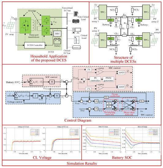
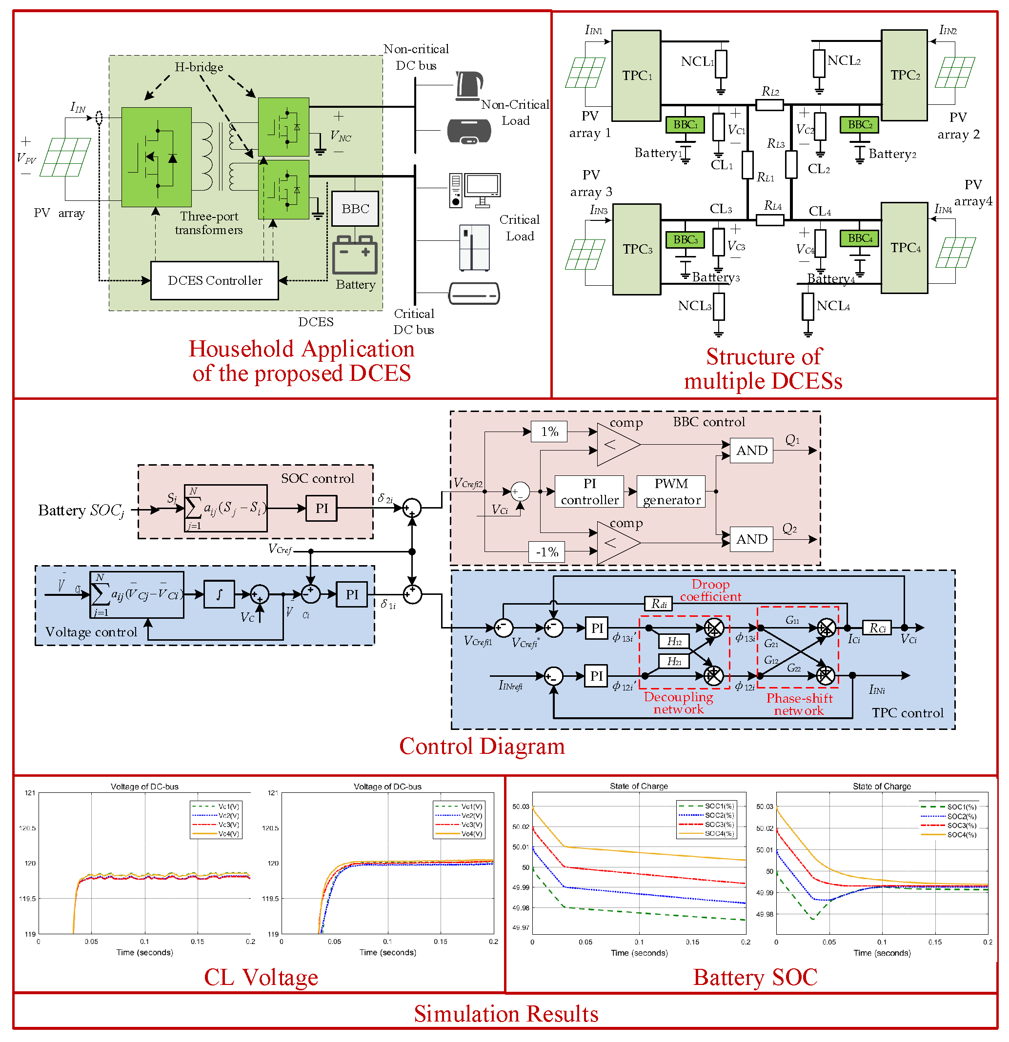
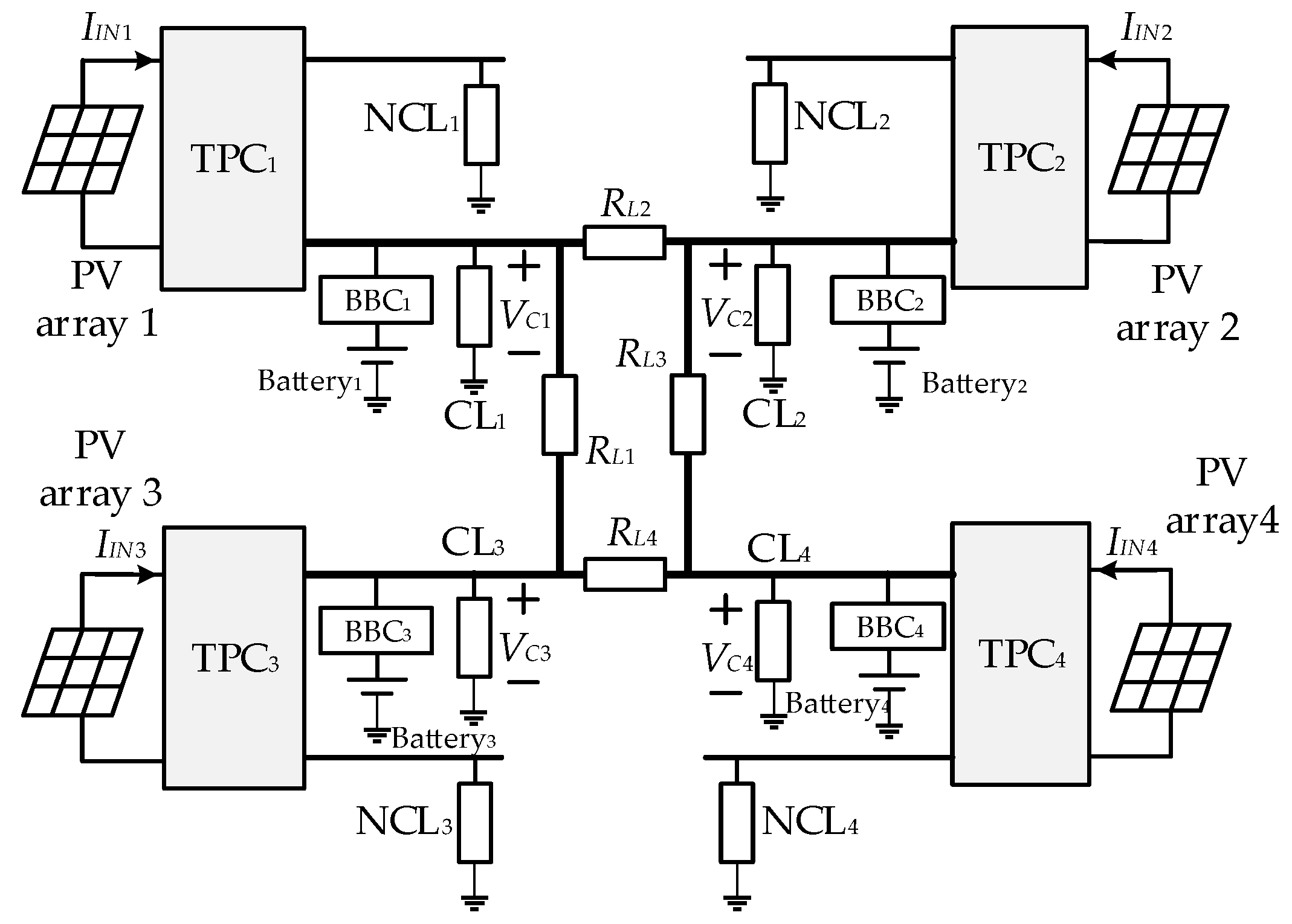
2. DCES Topology and Operation

This paper utilizes DCESs with the CLP-ESU topology drawn within the dashed line of Figure 1. The photovoltaic (PV) array, NCL and CL are connected to the ports of the TPC, which is essentially a two-output DC/DC converter isolated by means of a high frequency transformer and equipped with a full AC/DC bridge at each port. The battery is used for voltage regulation, and is paralleled to the CL DC bus through the BBC, which can be thought of as a version of the boost DC/DC converter, modified to support the bi-directional power flow. Compared to the existing DCES ones, the CLP-ESU topology keeps the supply of the CL and NCL isolated from each other. This circuital layout is compliant with the traditional way of connecting loads with different requirements in a power system [12]. More broadly, it can be envisaged that each output port in the figure supplies a distinct DC bus with connecting as many CLs and NCLs as per the DCES sizing power.
The typical operating modes of the DCES are three, designated as the battery-balancing mode, battery-discharging mode, and battery-charging mode.
In the battery-balancing mode (mode 1), the power delivered by the RES is enough to supply CL at the specified value. The RES power fluctuations are forced by the ESU to flow almost entirely from the RES to the NCL, whilst the remaining small part of them flows into the battery to keep the CL voltage stabilized.
In the battery-discharging mode (mode 2), the RES power is in-sufficient to supply CL at the rated value even if the NCL voltage is adjusted to consume less power than the rated one. In this mode, the battery discharges to provide the deficit of power to the CL.
At the battery-charging mode (mode 3), the RES power exceeds the power consumption of CL even if the NCL voltage is adjusted to consume more power than the rated one. In this mode, the battery is charged and stores the excess of power.
The structure of multiple DCESs in a DC microgrid is schematized in Figure 2. The figure shows that the CL DC buses (henceforth briefly referred to as the DC buses) of each DCES are connected to each other by transmission lines, whose resistances are denoted with RL1, RL2, RL3, and RL4. The link of the four DCESs together forms a typical DC microgrid.

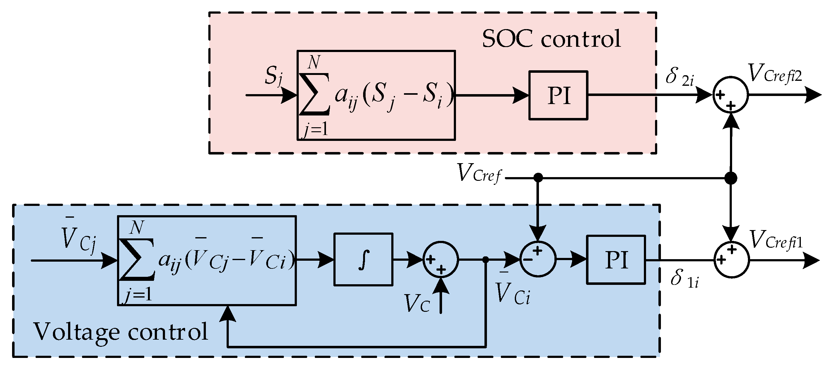
3. Distributed Cooperative Control

3.1. Primary Control

The primary control, also named the local voltage control, provides the independent voltage control of each DCES. It exerts into two control actions, namely the TPC control and BBC control. As shown by the scheme in Figure 3, the TPC control regulates the power flow from the RES to the CL and NCL by changing the phase-shift angle, whilst the BBC control aims for a power regulation of the CL.
The TPC control encompasses three actions: Phase-shift control, decoupling network, and adaptive droop adjustment, as drawn in the diagram of Figure 4 for the ith DCES.
The familiar phase-shift control [21] is adopted for TPC to change the power flow from port I to port II and III, where ϕ12 and ϕ13 are the phase-shift angles of the drive signals of the H-bridges at ports I and II, and at ports I and III, respectively, so as to regulate the CL voltage to be constant.
The two ports of the TPC can be regarded as a DAB. As a result, the power equations can be obtained through a superposition theorem and the results are as follows [22].
{ P 12 = V I N V N C 2 π f s L 12 ϕ 12 ( 1 ϕ 12 π ) P 13 = V I N V C 2 π f s L 13 ϕ 13 ( 1 ϕ 13 π ) P 32 = V N C V C 2 π f s L 23 ϕ 32 ( 1 ϕ 32 π )
where fs denotes the switching frequency; P12, P13, and P32 denote the power flowing from port I to port II, from port I to port III and from port III to port II, respectively. VNC′ and VC′ denote the voltages VNC and VC reflected to port I from port II and port III, respectively. It should be noticed that the power flow is determined by the phase-shift angle between the related two ports.
Based on P1 = P12 + P13 and P3 = P32P13, the averaged values of the currents at port I and port III can be expressed as
{ I I N = P 1 V I N = N 1 V N C 2 π f s N 2 L 12 ϕ 12 ( 1 ϕ 12 π ) + N 1 V C 2 π f s N 3 L 13 ϕ 13 ( 1 ϕ 13 π ) I C = P 3 V C = N 1 V I N 2 π f s N 3 L 13 ϕ 13 ( 1 ϕ 13 π ) N 1 2 V N C 2 π f s N 2 N 3 L 23 ϕ 32 ( 1 ϕ 12 ϕ 13 π )
where IIN and IC denote the averaged currents at port I and port II, respectively.
It is obviously seen that both the power and current equations are nonlinear forms. To obtain the small signal model, a small-signal perturbation in the form of a small step change is applied around a quiescent operation point, which is designated as Q(ϕ130, ϕ120).
The elements of the relationship matrix between the current and phase angles are as follows.
{ G 11 = I 3 ϕ 13 | Q = N 1 V 1 2 π f s N 3 L 13 ( 1 2 π ϕ 130 ) + N 1 2 V 2 2 π f s N 2 N 3 L 23 [ 1 2 π ( ϕ 120 ϕ 130 ) ] G 12 = I 3 ϕ 12 | Q = N 1 2 V 2 2 π f s N 2 N 3 L 23 [ 1 2 π ( ϕ 120 ϕ 130 ) ] G 21 = I 1 ϕ 13 | Q = N 1 V 3 2 π f s N 3 L 13 ( 1 2 π ϕ 130 ) G 22 = I 1 ϕ 12 | Q = N 1 V 2 2 π f s N 2 L 12 ( 1 2 π ϕ 120 )
The equations of the small signal modeling of the TPC could be expressed as follows.
[ Δ I I N Δ I C ] = [ G 11 G 12 G 21 G 22 ] [ Δ ϕ 13 Δ ϕ 12 ] = G [ Δ ϕ 13 Δ ϕ 12 ]
where ΔIIN, ΔIC, Δϕ13, and Δϕ12 are the small-signal perturbation of IIN, IC, ϕ13, and ϕ12, respectively.
G = [ G 11 G 12 G 21 G 22 ]
In Figure 4, since the CL voltage VC = ICRC and input port current IIN are influenced by both ϕ12 and ϕ13, a decoupling network is inserted in the TPC control [23] to eliminate the cross influence of the phase angles on the control of VC and IIN. A decoupling matrix H is designed to make GH a diagonal matrix to ensure one output is determined by one control input independently. As a result, two equations could be obtained as follows:
{ Δ ϕ 12 G 21 + Δ ϕ 12 H 21 G 22 = 0 Δ ϕ 13 G 12 + Δ ϕ 13 H 12 G 11 = 0
where Δϕ13’ and Δϕ12’ are the small-signal perturbation of the virtual phase-shift angle derived from Δϕ13 and Δϕ12 in the decoupling control.
Therefore, H can be derived and simplified as
H = [ 1 H 21 H 12 1 ] = [ 1 G 12 / G 11 G 21 / G 22 1 ]
In the control system, there are two control loops, the output voltage loop is designed for port III and the input current loop is related to port I. After the design of the decoupling network, it can be assumed that there are no interactions between these loops.
More details about the phase-shift control and decoupling control of DCES with the CLP-ESU topology can be found in [12].
The third action of the TPC control is the adaptive droop [24] adjustment based on the consensus algorithm, which is firstly utilized in the proposed primary TPC control compared to the existing literature [25]. It is utilized to establish the individual power allocation for each DCES by changing the virtual equivalent resistance Rdi (droop coefficient) in the diagram of Figure 4. The modified CL voltage reference V C r e f i * of the ith DCES is obtained by
V C r e f i = V C r e f i 1 R d i I C i
where ICi and Rdi is the CL current and droop coefficient of the ith DCES, respectively. VCrefi1 is the voltage reference generated by the secondary voltage control, as explained later on.
Thus, the voltage droop can be adjusted to comply with the different load conditions of the DCESs. The adjustment is obtained by updating the droop coefficient Rdi as follows:
R d i = R d 0 δ R d i
where, Rd0 is the initial droop coefficient, and δRdi is its correction term. The calculation of this term is based on the consensus algorithm.
The principle of an average consensus algorithm is explicated in [18]. Let xi be the state variable of node i in a system, and let node i communicate with its neighboring node j under a communication weight aij, the system is in consensus only when all the state variables are equal to each other. To reach the consensus situation, the state variable xi is updated at time t by
x ˙ i ( t ) = j = 1 n a i j ( x j ( t ) x i ( t ) ) , i = 1 , 2 , , n
where the dot over xi denotes the updated value of xi. The communication weight aij is a positive quantity that indicates if there is an exchange of information from node j to i and how much valued is the information. Specifically, aij > 0 means that there is communication between nodes j to i, whilst aij = 0 means there is no communication; moreover, a large value of aij indicates that node j has a high degree of influence on the update of the state variable of node i.
The final result of a consensus algorithm is that the state variables of each nodes approach the average of the initial values of all the nodes.
lim t x i ( t ) = 1 n i = 1 n x i ( 0 ) , i = 1 , 2 , , n
Based on the consensus algorithm, the correction term δRdi is carried in four steps: (i) Comparison of current ICi of ith CL to that of jth CL neighbor, (ii) weighting of the current difference (ICjICi) with weight aij, (iii) summation of the weighted current differences of the N neighbors, and iv) entering of the summation into a PI controller [24].
δ R d i = k P I i j = 1 N a i j ( I C j I C i ) + k I I i j = 1 N a i j ( I C j I C i ) d t
As a result, the update of Rd affects the output current and, hence, the output power of each DCES.
The BBC control for the ith DCES has the diagram in Figure 5, where the voltage reference VCerfi2 is generated by the secondary SOC control. It is worthy to note right now that, in general, VCerfi1 and VCerfi2 are different since they are generated respectively by the secondary voltage and SOC controls. The reference VCrefi1 is used to control the TPC and regulate the power consumption of NCL, while the reference VCrefi2 is used to change the operation mode of BBC and regulate the power of the battery. The switching signals of the BBC switches Q1 and Q2 are delivered by two logic AND elements triggered by the output of a PI controller through the PWM generator and the outputs of two comparators.
The operation of the BBC control is as follows. When voltage VCi of ith CL DC-bus is higher than a predefined value of the reference (e.g., VCi > 1.01VCrefi2), BBC enters into the buck mode, and DCES operates in the battery-charging mode. When VCi is lower than a predefined value of the reference (e.g., VCi < 0.99VCrefi2), BBC enters into the boost mode, and the DCES operates in the battery-discharging mode. When VCi is in between 0.99VCrefi2 and 1.01VCrefi2, the two sides of BBC are isolated from each other, and the DCES operates in the battery-balancing mode.

3.2. Secondary Control

The secondary control provides for generating the updated local values of references VCrefi1 and VCrefi2 for the two actions of the primary control. The diagram of the secondary control for ith DCES, drawn in Figure 6, underlines the two updating paths and the usage of two controls, one in the updating path of the CL DC-bus voltage, and the other one in that of the battery SOC. The operation of the secondary control relies on the average consensus algorithms.
Returning to the diagram of Figure 6, the voltage control updates the average voltage V ¯ C i of ith CL DC bus, by processing the local voltage measurement VCi and the neighbors’ average voltage V ¯ C j [26] through a consensus algorithm. It is expressed by
V ¯ C i = V C i j = 1 n a i j ( V ¯ C i V ¯ C j ) d t
After comparison of V ¯ C i to the global voltage reference VCref of the CL DC-bus voltage of the microgrid, the error term is processed by a PI controller, as formulated in (8), to generate a correction term δ1i for the voltage reference VCerfi1 of the TPC control of ith DCES.
δ 1 i = k P U i ( V C r e f V ¯ C i ) + k I U i ( V C r e f V ¯ C i ) d t
where the kPUi and kIUi are the proportional and integral coefficients of the voltage control. In agreement with (14), the correction term δ1i is higher when the average voltage V ¯ C i greatly deviates from reference VCref. As shown by (15), this fact enforces reference VCrefi1 of the TPC control so as to realize the consensus of V ¯ C i and VCref, which means that the average CL DC-bus voltage are regulated very close to the rated value [20].
V C r e f i 1 = V C r e f + δ i 1
To realize the consensus of the SOC of the batteries in a multiple DCES, the SOC control of Figure 6 compels batteries with a high SOC to discharge faster and those with low SOC to charge faster. For this purpose, the following local state variable Si is defined for the SOC of the battery of ith DCES [19]:
S i = P b i C i F S O C i = V b i i b i C i F S O C i
where Pbi indicates the power flow at the battery terminals (marked as negative during charging and positive during discharging), SOCi is the SOC of the battery of ith DCES, and FSOCi is a function of SOCi defined as
F S O C i = { S O C i S O C L , P b i > 0 S O C H S O C i , P b i < 0
where SOCL and SOCH are respectively the lower and upper limits of SOCi, which are selected as 0.2 and 0.8 in this paper.
By help of a consensus algorithm, the updated value of Si is processed by a PI controller, as formulated in (18), to generate a correction term δ2i for the voltage reference VCerfi2 of the BBC control of ith DCES.
δ 2 i = k P S i j = 1 N a i j ( S j S i ) + k I S i j = 1 N a i j ( S j S i ) d t
where the kPSi and kISi indicate the proportional and integral coefficient of the SOC control.
Similar to the update of the voltage reference VCerfi1, a correction term δ2i becomes higher when Si greatly deviates from the neighboring Sj. As shown by (19), this fact enforces reference VCrefi2 of the BBC control and, together with it, the charging or discharging process of the batteries so as to realize the consensus of SOCi and SOCj.
V C r e f i 2 = V C r e f + δ i 2
The structure of the distributed cooperative system arranged for the control of multiple DCESs is illustrated by the block diagram in Figure 7. The diagram highlights that the system has two control levels, including the primary control and secondary control. Compared to the existing distributed cooperative control [27], the voltage references of the TPC and BBC controls that are located in the primary control level, are generated respectively by the voltage and SOC controls that are located in the secondary control level. It means that the TPC and BBC can be controlled independently, which contributes to a reduced battery usage and releases the burden of the battery.

4. Steady State Analysis

In this section, the steady state analysis of the distributed cooperative control is carried out to prove the consensus of the CL average voltage and battery SOC.

4.1. Consensus of the CL Average Voltage

By differentiating (13),
d V ¯ C i = d V C i j = 1 n a i j ( V ¯ C i V ¯ C j )
The global observer dynamic can be formulated as
d V ¯ C = d V C L V ¯ C
where L = D A , in which D = d i a g { j = 1 n a i j } , A = [ a i j ] R n × n , V C = [ V C 1 , V C 2 , , V C n ] T and V ¯ C = [ V ¯ C 1 , V ¯ C 2 , , V ¯ C n ] T is the CL DC-bus voltage vector and CL average voltage vector, respectively. Since V ¯ C ( 0 ) = V C ( 0 ) , (21) can be written in the frequency domain as
V C s ¯ = s ( s I + L ) 1 V C s = H V C s
where V C s ¯ and V C s are the form in frequency domain of V ¯ C and V C .
The correction term in (14) can be written in the frequency domain as
δ 1 = G U ( V C r e f V C s ¯ )
where VCref is the Laplace transform of the reference voltage vector, and lim s 0 s V C r e f = V C r e f 1 n in which 1n is a column vector with all elements equal to 1 [27]. GU = diag{GUi}, in which
G U i = k P U i + k I U i s
combining (8) and (15), then write it in the frequency domain by substituting (22) and (23)
V C r e f = V C r e f 1 I C R d = V C r e f + G U ( V C r e f H V C s ) I C R d
where Rd = diag{Rdi}is the droop coefficient matrix, and IC is the Laplace transform of the CL current vector [ I C 1 , I C 2 , , I C n ] T
Thus, the dynamic behavior of the CL DC bus voltage with a closed-loop voltage regulator can be expressed as
V C s = G C 1 V C r e f
where GC1 = diag{GC1i} is the transfer function matrix, in which GC1i is the closed-loop transfer function of the ith TPC of DCES, and can be simplified as an inertial element
lim s 0 G C 1 = I n
where In is a n-order unit matrix.
The CL current matrix IC can be obtained by the admittance matrix Y of the DCESs
I C = Y V C s
By substituting (26) and (28) into (25), the dynamic behavior of the CL DC bus voltage can be written as
V C s = ( I n + G C 1 G U H + G C 1 R d Y ) 1 × G C 1 ( I + G U ) V C r e f
The steady state of the CL DC bus voltage can be obtained as
V C s s = lim s 0 s V C s = lim s 0 [ s ( s I n + s G C 1 G U H + s G C 1 R d Y ) 1 × s G C 1 ( I n + G U ) V C r e f ]
Based on the definition of GU, it can be obtained as
lim s 0 s G U = K I U
Therefore,
Q V C s s = lim s 0 s H V C s = ( K I U ) 1 × K I U V C r e f 1 n = V C r e f 1 n
where Q = lim s 0 H is the n × n matrix with all the elements equal to 1/n. So, the steady state of the CL average voltage can be written as
V C s s ¯ = Q V C s s = V c r e f 1 n
Equation (33) implies that the CL average voltage will all reach consensus in the steady state at VCref.

4.2. Consensus of the Battery SOC

The correction term in (18) can be written in the frequency domain as
δ 1 = G S L S
where S is the Laplace transform vector of the state variable in (16).
By substituting (34), (19) can be written in the frequency domain
V C r e f 2 = V C r e f + G S L S
Similar to (26),
V C s = G C 2 V C r e f 2
where GC2 = diag{GC2i} is the transfer function matrix, in which GCi is the closed-loop transfer function of the ith BBC of DCES, and can be simplified as an inertial element.
lim s 0 G C 1 = I n
Therefore, S can be written as
S = ( G C 2 G S L ) 1 × ( V C s G C 2 V C r e f )
Based on the definition of GS, it can be obtained as
lim s 0 s G S = K I S
The form of the state variable S in the frequency domain is Ss, and its steady state can be obtained as
S s s = lim s 0 s S s = lim s 0 [ s ( s G C 2 G S L ) 1 × ( s V C s s G C 2 V C r e f ) ]
Therefore, QSss can be written as
Q S s s = lim s 0 s H S = lim s 0 [ s H ( s G C 2 G S L ) 1 × ( s V C s s G C 2 V C r e f ) ] = lim s 0 [ s ( K I S L ) 1 × ( I n Q ) V C r e f 1 n ) = 0 n
It can be seen that Sss is the eigenvector of Q associated with the eigenvalue zero, which ensures the state variable Si consensus. [27] According to the property of the Laplace matrix [28], the final consensus values can be obtained as
S s s = S s s 1 n
where Sss is the positive real value to which all the state variables Si will be converged.
Equations (33) and (42) shows that the average bus voltage and battery SOC will all reach consensus in the steady state.

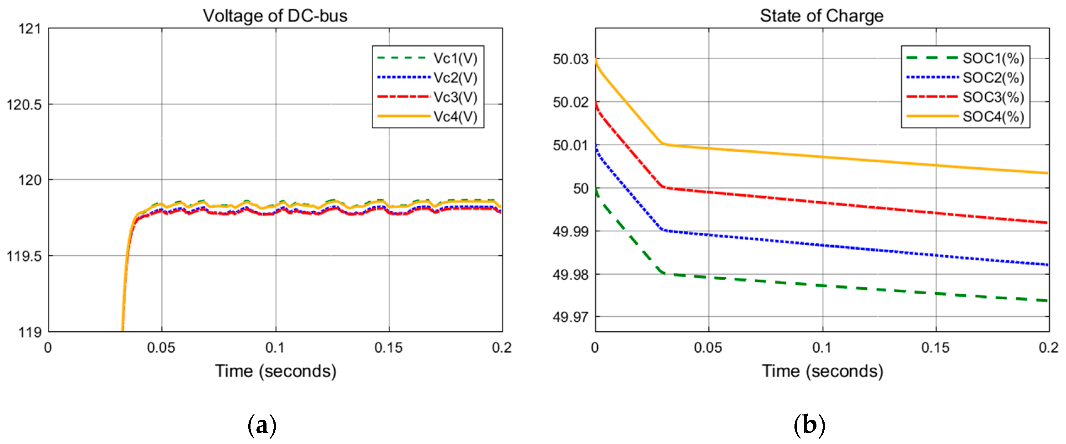
5. Simulation Results

Simulations are performed in the MATLAB/Simulink (2017a, MathWorks, Natick, MA, USA) to validate the performance of the proposed distributed cooperative control for the multiple DCESs. Table 1 reports the parameters of the study case utilized for simulation. To simplify the controller design, the communication weights are set to one. To verify the proposed distributed cooperative control, the resistance combinations of the CL and the NCL for the four DCESs are different from each other. Moreover, the droop coefficients of the four DCESs are also different according to the different output power.
The performance of the primary control and distributed cooperative control is discussed in detail as follows including the steady state, converter failure, communication weight variation, and load variation.

5.1. Steady State

This case validates the distributed cooperative control when the DCESs are at a steady state, by comparing the performance of the droop control and consensus control. The simulation results of the primary control and distributed cooperative control of this multiple DCESs are shown in Figure 8 and Figure 9, respectively.
In Figure 8, with only the primary control, the CL DC bus voltage is regulated to 119.2 V but deviates from the reference value of 120 V because of the droop gains and power allocation. The SOCs of the four batteries, whose initial value SOC0 are different from each other, are still in difference after the discharging. In Figure 9, the distributed cooperative control is simulated. It can be seen that the CL DC bus voltages between the four DCESs are in consensus and the average value is regulated to the rated value, owing to the secondary voltage control. However, the CL DC bus voltage of the individual DCES may differ from the rated value. Moreover, the SOCs eventually converge toward consensus thanks to the fact that the secondary SOC control forces the batteries with a high SOC to be discharged faster and meanwhile the batteries with a low SOC to be charged faster.

5.2. Converter Failure

This case illustrates the performance of the proposed control in the case of one converter failure. One DCES failure means that the output power of the DCES is zero. This happens when the DCES is shorted or broken, such as the short-circuit of the power switches and the open-circuit of the three-winding transformers. It is studied in this case to analyze the emergency performance of the proposed distributed cooperative control compared to the primary control. In this case, the output power of DCES1 reduces to zero at 0.1 s. The remaining DCESs carry out the power sharing by exchanging the SOC information with neighbors. In Figure 10, the four DC-bus voltages all deviate much from the rated value after the failure. In Figure 11, although the bus voltage of the DCESs cannot be regulated to a common value, with the distributed cooperative control, the average value of the remaining three DC-bus voltages are regulated close to the rated value if ignoring the small DC-bus voltage drop of DCES1. Moreover, the control can drive the four battery SOCs to consensus and balance.

5.3. Communication Weight Variation

In this case, the effect of the communication weight on the speed of the system convergence is investigated. It can be seen from Equations (13), (14), and (18) that the communication weight aij affects the correction term δ1i and δ2i, which will affect the voltage reference. To simplify the controller design, in Figure 9 and Figure 12, the communication weights aij are set to one for normal impact levels and five for high impact levels, respectively.
It can be seen in Figure 12a that the average CL DC-bus voltages reach the rated value for about 0.07 s regardless of the value of communication weight aij. Therefore, the communication weight has a weak impact on the convergence speed of the CL DC-bus voltage. However, in Figure 12b, the SOCs reach the consensus state faster with a larger aij. It can be concluded that a larger communication weight contributes to a faster convergence speed of SOC.

5.4. Load Variation

This section discusses the performance of the proposed distributed cooperative control compared to the primary control in the case of one load variation. The CL of DCES1 changes from 120 Ω to 80 Ω at 0.1 s.
It can be seen in Figure 13 that the four DC-bus voltages deviated from the rated value especially after the load variation at 0.1 s. Moreover, the four SOCs are still different from each other. However, in Figure 14, with the distributed cooperative control, the four DC-bus voltages are in consensus, the average bus voltage can be regulated close to the rated value and four battery SOCs reach the consensus state although the load variation is at 0.1 s. This study indicates the good performance of the proposed control method when the CL load varies.

6. Conclusions

A distributed cooperative control is proposed for multiple DC electric springs with the recently proposed topology in this paper. The novel DCES, which is composed of the DC/DC three port converter, bi-directional buck-boost converter, and battery system, can realize electrical isolation between the CL and the NCL and can also realize the traditional paralleled connection way of the electrical loads. The proposed distributed cooperative control composed of the primary control and the secondary control, can be used to realize the local voltage stability, power allocation of multiple DCESs and the consensus of DC-bus voltages and battery SOCs among multiple DCESs. The primary control is made up of the phased-shift control, decoupling control, adaptive droop control, and charging/discharging control. Furthermore, the secondary control consists of the voltage control and SOC control. The proposed distributed cooperative control applied in multiple DCESs with the recently proposed topologies has been validated by the simulation results.

Author Contributions

Conceptualization, D.Z., Q.W. and M.C.; methodology, Q.W.; software, D.Z.; validation, D.Z., Q.W.; formal analysis, F.D.; investigation, D.Z.; resources, Q.W.; data curation, Q.W.; writing—original draft preparation, D.Z.; writing—review and editing, D.Z., Q.W., G.B.; visualization, F.D.; supervision, M.C.; project administration, Q.W.; funding acquisition, Q.W.

Funding

This work was supported by the Natural Science Foundation of Jiangsu Province under project BK20170675, and by the National Natural Science Foundation of China under project 51877040.

Conflicts of Interest

The authors declare no conflict of interest.

References

  1. Hui, S.Y.; Lee, C.K.; Wu, F.F. Electric springs—A new smart grid technology. IEEE Trans. Smart Grid 2012, 3, 1552–1561. [Google Scholar] [CrossRef]
  2. Wang, Q.; Cheng, M.; Jiang, Y.; Zuo, W.; Buja, G. A Simple Active and Reactive Power Control for Applications of Single-Phase Electric Springs. IEEE Trans. Ind. Electron. 2018, 65, 6291–6300. [Google Scholar] [CrossRef]
  3. Wang, Q.; Cheng, M.; Chen, Z. Steady-state analysis of electric springs with a novel δ control. IEEE Trans. Power Electron. 2015, 30, 7159–7169. [Google Scholar] [CrossRef]
  4. Mok, K.; Wang, M.; Tan, S.; Hui, S.Y.R. DC electric springs—A technology for stabilizing DC power distribution systems. IEEE Trans. Power Electron. 2017, 32, 1088–1105. [Google Scholar] [CrossRef]
  5. Wang, Q.; Cheng, M.; Jiang, Y.; Chen, Z.; Deng, F.; Wang, Z. DC electric springs with DC/DC converters. In Proceedings of the IEEE International Power Electronics and Motion Control Conference, Hefei, China, 28 September 2016; pp. 3268–3273. [Google Scholar]
  6. Wang, M.; Yang, T.; Tan, S.; Hui, S.Y. Hybrid Electric Springs for Grid-Tied Power Control and Storage Reduction in AC Microgrids. IEEE Trans. Power Electron. 2019, 34, 3214–3225. [Google Scholar] [CrossRef]
  7. Kakigano, H.; Miura, Y.; Ise, T. Distribution Voltage Control for DC Microgrids Using Fuzzy Control and Gain-Scheduling Technique. IEEE Trans. Power Electron. 2013, 28, 2246–2258. [Google Scholar] [CrossRef]
  8. Ahmadi, R.; Ferdowsi, M. Improving the Performance of a Line Regulating Converter in a Converter-Dominated DC Microgrid System. IEEE Trans. Smart Grid 2014, 5, 2553–2563. [Google Scholar] [CrossRef]
  9. Huang, P.; Liu, P.; Xiao, W.; El Moursi, M.S. A Novel Droop-Based Average Voltage Sharing Control Strategy for DC Microgrids. IEEE Trans. Smart Grid 2015, 6, 1096–1106. [Google Scholar] [CrossRef]
  10. Rouzbehi, K.; Miranian, A.; Luna, A.; Rodriguez, P. DC Voltage Control and Power Sharing in Multiterminal DC Grids Based on Optimal DC Power Flow and Voltage-Droop Strategy. IEEE J. Emerg. Sel. Top. Power Electron. 2014, 2, 1171–1180. [Google Scholar] [CrossRef]
  11. Mok, K.; Wang, M.; Tan, S.; Hui, S. DC electric springs—An emerging technology for DC grids. In Proceedings of the IEEE Applied Power Electronics Conference and Exposition, Charlotte, NC, USA, 15–19 March 2015; pp. 684–690. [Google Scholar]
  12. Wang, Q.; Zha, D.; Deng, F.; Cheng, M.; Buja, G. A topology of DC electric springs for DC household applications. IET Power Electron. 2019, 12, 1241–1248. [Google Scholar] [CrossRef]
  13. Phattanasak, M.; Gavagsaz-Ghoachani, R.; Martin, J.; Nahid-Mobarakeh, B.; Pierfederici, S.; Davat, B. Control of a hybrid energy source comprising a fuel cell and two storage devices using isolated three-port bidirectional DC–DC converters. IEEE Trans. Ind. Appl. 2015, 51, 491–497. [Google Scholar] [CrossRef]
  14. Bahrami, H.; Farhangi, S.; Iman-Eini, H.; Adib, E. A new interleaved coupled-inductor nonisolated soft-switching bidirectional DC/DC converter with high voltage gain ratio. IEEE Trans. Ind. Electron. 2018, 65, 5529–5538. [Google Scholar] [CrossRef]
  15. Xu, Y.; Zhang, W.; Hug, G.; Kar, S.; Li, Z. Cooperative control of distributed energy storage systems in a microgrid. IEEE Trans. Smart Grid 2015, 6, 238–248. [Google Scholar] [CrossRef]
  16. Mokhtari, G.; Nourbakhsh, G.; Ghosh, A. Smart coordination of energy storage units (ESUs) for voltage and loading management in distribution networks. IEEE Trans. Power Syst. 2013, 28, 4812–4820. [Google Scholar] [CrossRef]
  17. Zhang, X.; Dong, M.; Ou, J. A distributed cooperative control strategy based on consensus algorithm in DC microgrid. In Proceedings of the IEEE Conference on Industrial Electronics and Applications, Wuhan, China, 31 May–2 June 2018; pp. 243–248. [Google Scholar]
  18. Olfati-Saber, R.; Fax, J.A.; Murray, R.M. Consensus and cooperation in networked multi-agent systems. Proc. IEEE USA 2007, 95, 215–233. [Google Scholar] [CrossRef]
  19. Golsorkhi, M.S.; Shafiee, Q.; Lu, D.D.; Guerrero, J.M. A distributed control framework for integrated photovoltaic-battery-based islanded microgrids. IEEE Trans. Smart Grid 2017, 8, 2837–2848. [Google Scholar] [CrossRef]
  20. Chen, X.; Shi, M.; Sun, H.; Li, Y.; He, H. Distributed cooperative control and stability analysis of multiple DC electric springs in a dc microgrid. IEEE Trans. Ind. Electron. 2018, 65, 5611–5622. [Google Scholar] [CrossRef]
  21. Zhang, J.; Wu, H.; Qin, X.; Xing, Y. PWM plus secondary-side phase-shift controlled soft-switching full-bridge three-port converter for renewable power systems. IEEE Trans. Ind. Electron. 2015, 62, 7061–7072. [Google Scholar] [CrossRef]
  22. Samir, H.; Subhashish, B.; Chandan, C. A novel control principle for a high frequency transformer based multiport converter for integration of renewable energy sources. In Proceedings of the IEEE Industrial Electronics Society. Annual. Conference, Vienna, Austria, 10–13 November 2013; pp. 7984–7989. [Google Scholar]
  23. Wang, W.; Wang, P.; Ma, T.; Liu, H.; Wu, H. A simple decoupling control method for isolated three-port bidirectional converter in low-voltage DC microgrids. In Proceedings of the IEEE Energy Conversion Congress and Exposition, Montreal, QC, Canada, 20–24 September 2015; pp. 3192–3196. [Google Scholar]
  24. Nasirian, V.; Davoudi, A.; Lewis, F.L.; Guerrero, J.M. Distributed adaptive droop control for dc distribution systems. IEEE Trans. Energy Convers. 2014, 29, 944–956. [Google Scholar] [CrossRef]
  25. Kim, S.Y.; Song, H.; Nam, K. Idling port isolation control of three-port bidirectional converter for EVs. IEEE Trans. Power Electron. 2012, 27, 2495–2506. [Google Scholar] [CrossRef]
  26. Nasirian, V.; Moayedi, S.; Davoudi, A.; Lewis, F.L. Distributed cooperative control of DC microgrids. IEEE Trans. Power Electron. 2015, 30, 2288–2303. [Google Scholar] [CrossRef]
  27. Chen, X.; Shi, M.; Zhou, J.; Chen, Y.; Zuo, W.; Wen, J.; He, H. Distributed cooperative control of multiple hybrid energy storage systems in a DC microgrid using consensus protocol. IEEE Trans. Ind. Electron. 2019, 1. [Google Scholar] [CrossRef]
  28. Olfati-Saber, R.; Murray, R.M. Consensus problems in networks of agents with switching topology and time-delays. IEEE Trans. Autom. Control 2004, 49, 1520–1533. [Google Scholar] [CrossRef]
Figure 1. Critical load paralleled-energy storage unit (CLP-ESU) topology of the DC electric spring (DCES).
Energies 12 03422 g001
Figure 2. Structure of multiple DCESs.
Energies 12 03422 g002
Figure 3. The proposed primary control of the DCES.
Energies 12 03422 g003
Figure 4. The control diagram of the three port converter (TPC).
Energies 12 03422 g004
Figure 5. The charging and discharging control of BBC.
Energies 12 03422 g005
Figure 6. The proposed secondary control of the DCES.
Energies 12 03422 g006
Figure 7. Structure of the proposed distributed cooperative control.
Energies 12 03422 g007
Figure 8. Only with the primary control of multiple DCESs: (a) DC-bus voltage; (b) battery SOC.
Energies 12 03422 g008
Figure 9. Distributed cooperative control of multiple DCESs: (a) DC-bus voltage; (b) battery SOC.
Energies 12 03422 g009
Figure 10. Only with the primary control when failure at 0.1 s of DCES1: (a) DC-bus voltage; (b) battery SOC.
Energies 12 03422 g010
Figure 11. Distributed cooperative control when failure at 0.1 s of DCES1: (a) DC-bus voltage; (b) battery SOC.
Energies 12 03422 g011
Figure 12. Distributed cooperative control when communication weights aij = 5: (a) DC-bus voltage; (b) battery SOC.
Energies 12 03422 g012
Figure 13. Primary control when the load variation is at 0.1 s of DCES1: (a) DC-bus voltage; (b) battery SOC.
Energies 12 03422 g013
Figure 14. Distributed cooperative control when the load variation is at 0.1 s of DCES1: (a) DC-bus voltage; (b) battery SOC.
Energies 12 03422 g014
Table 1. Parameters for simulations.
ParameterValues
Input Voltage (VIN)50 V
Global voltage reference of CL (VCref)120 V
Communication weights (aij)1
Resistance of the CL (RC)RC1, RC3120 Ω
RC2, RC4150 Ω
Resistance of the NCL (RNC)RNC1, RNC240 Ω
RNC3, RNC460 Ω
Initial droop coefficient (Rd0)Rd01

