Review

Overview of Recent Advancements in the Microbial Fuel Cell from Fundamentals to Applications: Design, Major Elements, and Scalability

1
Department of Biological Environment, Kangwon National University, Gangwon-do, Chuncheon 24341, Korea
2
Center of Excellence in Environmental Studies, King Abdulaziz University, Jeddah 21589, Saudi Arabia
3
Center of Excellence in Environmental Studies, Department of Chemistry, College of Science, King Abdulaziz University, Jeddah 21589, Saudi Arabia
4
Green Energy Institute, 177 Samhyangcheon-ro, Mokpo, Jeollanam-do 58656, Korea
*
Authors to whom correspondence should be addressed.
Energies 2019, 12(17), 3390; https://doi.org/10.3390/en12173390
Submission received: 25 June 2019 / Revised: 17 August 2019 / Accepted: 29 August 2019 / Published: 3 September 2019

Abstract

:
Microbial fuel cell (MFC) technology offers an alternative means for producing energy from waste products. In this review, several characteristics of MFC technology that make it revolutionary will be highlighted. First, a brief history presents how bioelectrochemical systems have advanced, ultimately describing the development of microbial fuel cells. Second, the focus is shifted to the attributes that enable MFCs to work efficiently. Next, follows the design of various MFC systems in use including their components and how they are assembled, along with an explanation of how they work. Finally, microbial fuel cell designs and types of main configurations used are presented along with the scalability of the technology for proper application. The present review shows importance of design and elements to reduce energy loss for scaling up the MFC system including the type of electrode, shape of the single reactor, electrical connection method, stack direction, and modulation. These aspects precede making economically applicable large-scale MFCs (over 1 m3 scale) a reality.

1. Introduction

Most conventional waste and wastewater treatment systems require high-energy inputs to operate, but some alternative treatment technologies can operate efficiently using much less energy. Since global fossil fuel resources are dwindling, more renewable and sustainable alternative clean energy sources are needed [1]. Efforts to employ microorganisms to convert into electricity biodegradable waste materials (substrates) and organic wastes that were once considered expensive to dispose of have brought attention to the microbial fuel cell (MFC) [2] and made it the technology of choice [3]. With this technology, bacteria are attached to the surface of the anode electrode forming a biofilm, which is then used as an electrochemical reaction catalyst to produce electricity. When used for waste and wastewater treatment, treatment using an MFC is effective as it is clean energy, quiet in performance, highly efficient, low in emissions, and has direct electricity recovery. There are many challenges facing MFC technology, which prevent it from providing market real time applications. Applications in real environments face many challenges including pH, electron transfer mechanism in the anodic chamber, temperature, terminal electron acceptors, substrate, the membrane and the electrode material, all of which can definitely influence the performance of MFCs [4]. These parameters related with MFC performance to reduce energy loss. There are several limitations for scale up the MFCs. Firstly, the volumetric power generation reduces proportionally when the volume of an MFC increase. For scaling up an MFC, a higher volume of bioreactors is required. The theoretical voltage output is around 1.1 V when oxygen is used for the electron acceptor in the MFC. The actual produced voltage is always lower than its ideal value due to multiple electrochemical losses: The activation loss, the Ohmic loss, and the mass transfer loss. Secondly, when multiple MFCs are electrically connected for voltage up, the electrochemical degradation occurs such as voltage reversal phenomenon.
The main goal of this paper is to address an issue of designing and scaling-up of MFCs, the developments in stacked MFCs with emphasis on optimization of the physical and electrochemical connection method for reducing energy loss. This review will be useful for researchers and engineers who are interested in installation of large-scale MFCs and initiation of their work in this area.

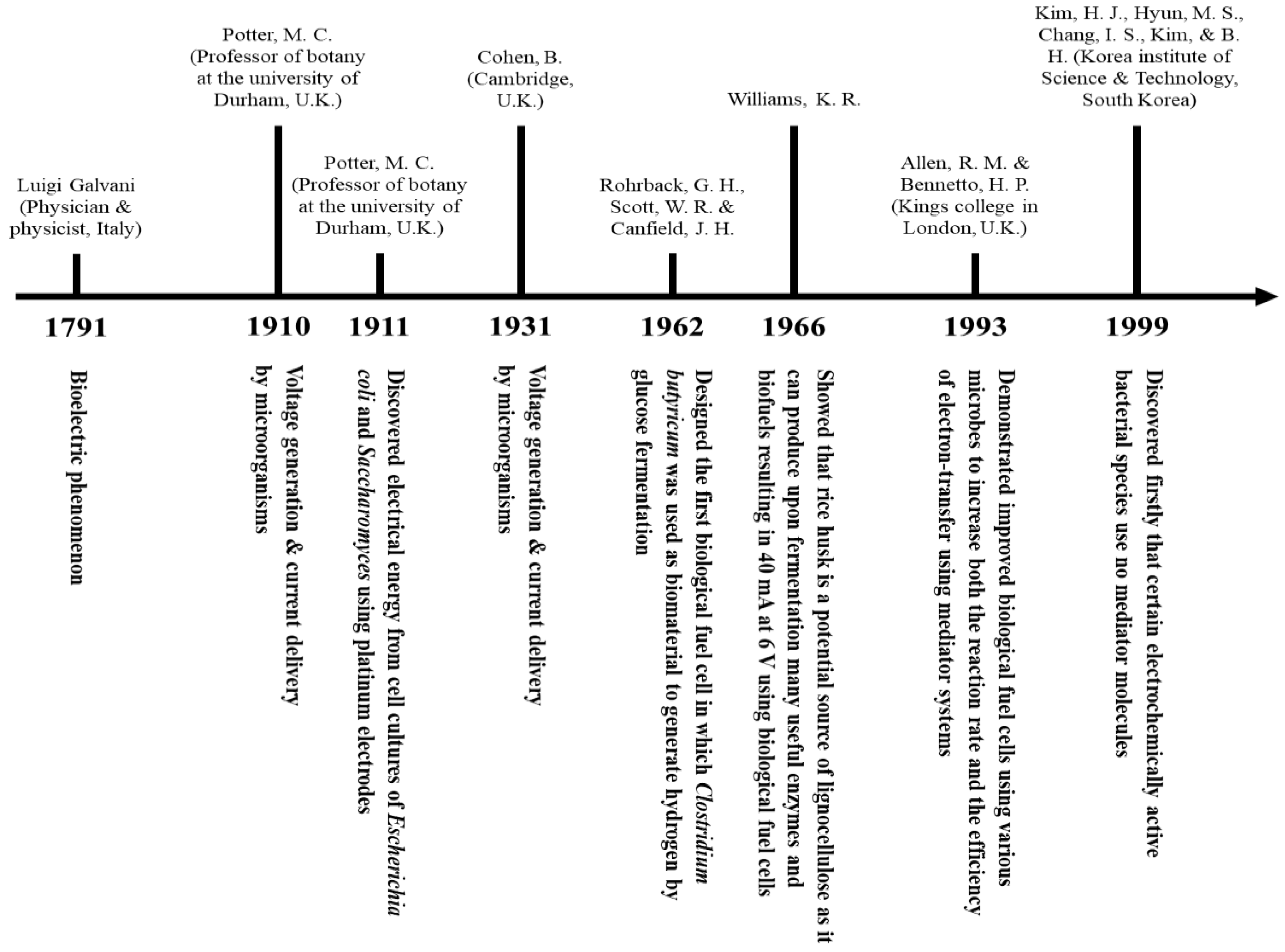
2. Microbial Fuel Cell Evolution

In 1791, the Italian physician and physicist, Luigi Galvani, who investigated the nature and effects of electricity in animal tissue was the first to observe a bioelectric phenomenon when he observed twitching of an isolated frog leg upon passing a brief electrical discharge through it. As a result, the term bioelectricity was coined after that observation [5]. In 1838, a Welsh physical scientist and lawyer, William Robert Grove, developed a wet-cell battery and called it the “Grove cell”. This is a two-fluid electric cell consisting of amalgamated zinc in dilute sulfuric acid and a platinum cathode in concentrated nitric acid, separating the two by a porous ceramic pot to generate about 12 amps of current at about 1.8 volts [6]. In 1893, a founder of the field of physical chemistry, Friedrich Wilhelm Ostwald, experimentally determined the interconnections between the various components of the fuel cell: Electrodes, electrolytes, oxidizing and reducing agents, anions, and cations by relating physical properties and chemical reactions. In 1910, Michael Cresse Potter, a professor of Botany at the University of Durham, UK, demonstrated that organisms could deliver current and produce voltage when he was researching how microorganisms degrade organic compounds [7]. Later in 1911, Potter discovered electrical energy from cell cultures of Saccharomyces and Escherichia coli using platinum electrodes [8]. This discovery led him to construct a basic microbial fuel cell [8]. In 1931, Cohen at Cambridge, UK, revived Potter’s idea when he described how a batch of biological fuel cells generated over 35 V [9]. In the 1960s, the idea of the fuel cell became popular when the Space Administration and National Aeronautics exhibited interest in converting organic waste into electricity on its long space flights. Bacteria and algae were among the first organisms used in biological fuel cells. During this period, the Rohrback group designed the first biological fuel cell in which Clostridium butyricum was used as biomaterial to produce hydrogen by glucose fermentation [10]. Quite quickly, the use of biological fuel cells as a power source became commercially available, but was unsuccessful, eventually disappearing from the market. In 1966, Williams showed that rice husk is a potential source of lignocellulose as it can produce upon fermentation many useful enzymes and biofuels resulting in 40 mA at 6 V using biological fuel cells [11]. The fuel cell revolution started when M. J. Allen and H. Peter Bennetto at Kings College, UK, demonstrated improved biological fuel cells using various microbes to increase both the reaction rate and the efficiency of electron-transfer using mediator systems [12]. They combined an understanding of the electron transport chain and significant advancements in technology. In 1999, certain electrochemically active bacterial species using no mediator molecules were first discovered by the Byung Hong Kim group (Korean Institute of Science and Technology, South Korea) to transport electrons to electrodes [13]. Using electrochemical tests, they found that the Shewanella sp. is capable of electrochemical reactions. Chaudhuri and Lovely have confirmed the finding by the Byung Hong Kim group by demonstrating that the R. ferrireducens microorganism can recover up to 83% of electrons from glucose oxidation (without a mediator) in the presence of Fe3+. Figure 1 shows a schematic demonstration of the timeline of the above history.

3. MFC Elements, Electron Transfer, and Principles of Working Machinery

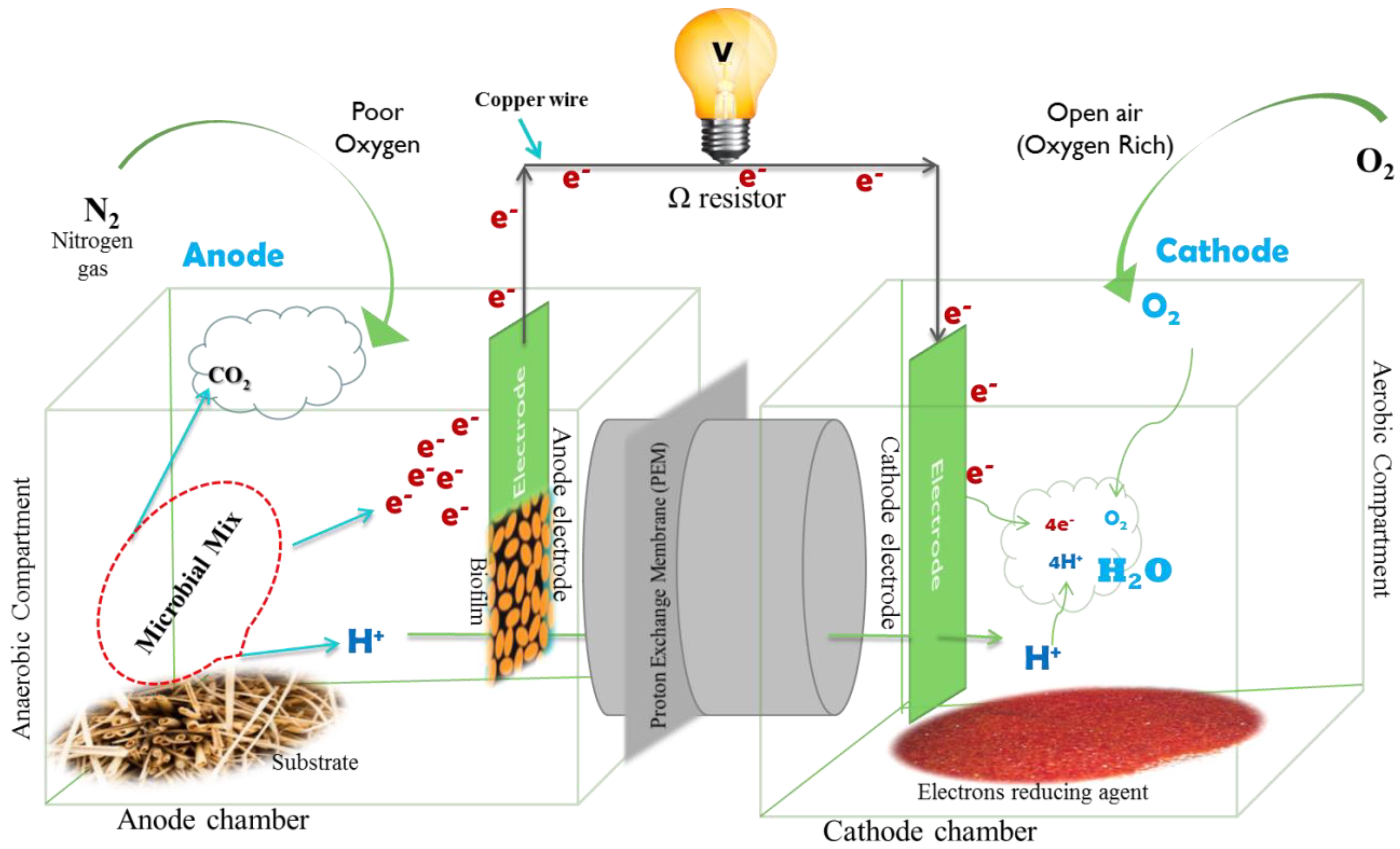
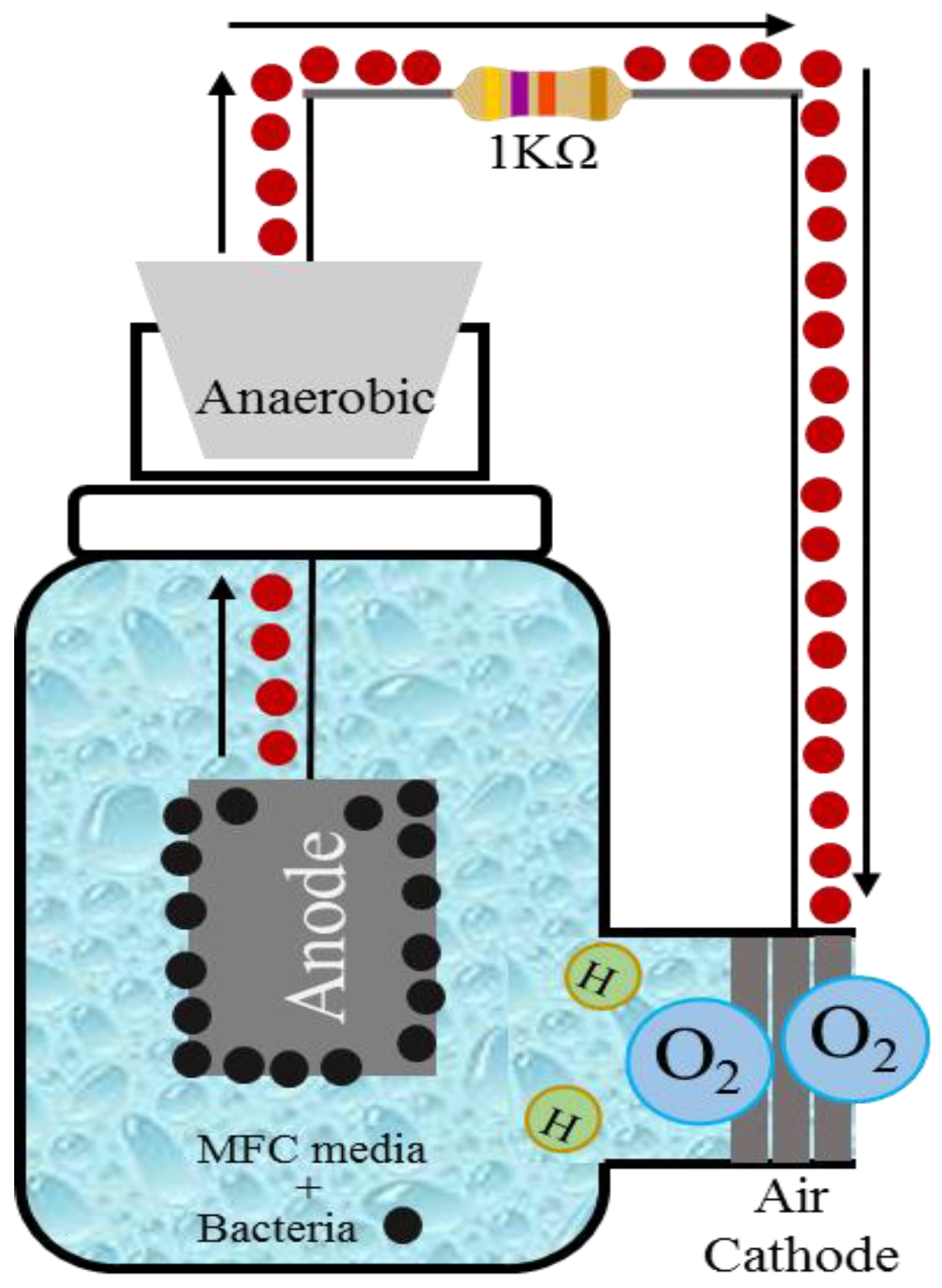
3.1. MFC Elements and Setup

The dual chamber design is used for explaining the basic mechanisms of MFCs. The dual chamber MFC apparatus (Figure 2) consists of anodic and cathodic chambers comprised of glass, polycarbonate, or Plexiglas, with a respective electrode of carbon paper, carbon-cloth, graphite, graphite felt, Pt, Pt black, or reticulated vitreous carbon. These two chambers are separated by a proton exchange membrane (PEM; Nafion or Ultrex) [14]. The anodic chamber contains organic matters that are metabolized by microorganisms for energy production and growth while generating protons and electrons. The cathode chamber contains a high potential electron acceptor to complete the circuit. To increase power density, an ideal electron acceptor is needed and must be sustainable with no interference or toxic effects on the microbial community or any other elements of the system in any way. Oxygen works as an ideal electron acceptor due to its richness, its non-toxicity, and is preferred to be an oxidizing agent as it simplifies the MFC operation. A standard oxidizing agent with a suitable electron acceptor such as ferricyanide can be also used [15]. Since microorganisms can generate electrochemically active substances that may be either the final products of anaerobic respiration or metabolic intermediaries [16], the MFC can be defined as a device using microbes to convert chemicals into electrical energy by a catalytic reaction [12]. MFCs are exceptional in using microorganisms to oxidize organic matter biologically and to produce and transfer electrons to the anode electrode surface to form a biofilm. This biofilm is used as a biocatalyst instead of precious metal catalysts such as platinum (Pt) to perform the required electrochemical redox reaction (catalytic oxidation at the anode and chemical reduction at the cathode).

3.2. MFC Electron Transfer

According to how electrons are transferred from the microorganisms to the anode, MFCs can be classified into two types: Mediator and mediatorless MFCs. In the mediator type of MFCs, microorganisms have no electrochemically-active-surface-proteins for transferring electrons to the anode electrode. As a result, they need agents to help them increase the availability of the transferred electrons and to transfer these electrons between the electrode and the microorganisms at relatively higher concentrations. These agents are called electroactive metabolites or mediators. Nevertheless, depending on the microorganism species involved, mediators may be synthetic, like neutral red, or natural, like sulfate/sulfide [17]. The microbial cells are set to enter the cell electron transport chain and to accept the electrons that are generated using inorganic mediators under anaerobic conditions. At this point, the mediators cross the outer cell lipid membranes and plasma wall and start liberating electrons from the electron transport chain, which is usually taken up by oxygen and other intermediates. Afterward, the reduced mediator exits the electron-loaded cell and deposits the carried electrons on the surface of the anode electrode. Hence, the anode electrode becomes negatively charged. Upon releasing the electrons, the mediator returns to its original oxidized state prepared to repeat the process. By contrast, under aerobic conditions, oxygen, having a higher electronegativity than the mediator, will collect all the electrons. Some mediators have been suggested to be used in microbial fuel cells including methylene blue, natural red, resorufin, or thionine [18]. The reduced mediator is oxidized when it deposits the carried electrons from the cell onto the anode electrode. Through the external circuit, the electrons then flow to the cathode electrode, which acts as an electron sink, and pass to an oxidizing material to complete the process. It should be noted that these electrons are consumed as an electric current to power electronic devices before they ultimately reach the oxygen at the cathode, which is what is required for optimal bacterial growth. Due to the high costs and toxicity of these mediators, it is necessary to develop alternatives to improve power production and decrease capital expense, making it suitable for a wastewater treatment process when the mediator-less MFCs are used. Furthermore, there are many additional drawbacks to using exogenous mediators, including high costs, short lifetimes, and toxicity to both the microorganisms themselves and to natural ecosystems. Therefore, it is crucial to develop mediator-less MFCs alternatives that are not only safer and cheaper to produce, but can also improve power production, thus making them suitable for use in wastewater treatment. In addition, when bacteria generate their own mediators or can directly transfer electrons to the electrodes, the activity of the MFC system can be sustained at a high intensity.
On the other hand, some microorganisms can generate electricity without mediators. These mediator-less types of MFCs are non-toxic and cheaper to produce than MFCs that require mediators. Mediator-less MFCs function without exogenous electron carriers. Instead, their electron transport relies mainly on metal-reducing bacteria, such as Shewanella [2,19,20] including Shewanella putrefaciens [21,22]; Rhodoferax [23]; Geobacteraceae including Geobacter sulfuurreducens [22]; and Geobacter metalli reducens [23]; Aeromonas hydrophila [24]; and Klebsiella pneumoniae [25,26]. Nonetheless, when mediatorless MFCs are operated, some factors have to be considered, such as the presence of electrochemically active redox enzymes for efficient electron transfer to the anode, fuel oxidation at the anode, the circuit’s external resistance, oxygen reduction at the cathode, and proton transfer through the membrane to the cathode as they limit the generation of electricity. When membrane proton permeability is sluggish, cathode chamber proton transfer can also be a limiting factor. Under these limitations, microbial activity and electron transfer to the electrode in the anode chamber can be reduced due to changes in pH, in addition to slow cathode reaction due to limited proton supply [27].
Geobacteraceae sp. transfers electrons directly to the anode via redox enzymes in the outer membrane. This mediator-less MFC captures monosaccharides and methanol from food leftovers converting them into hydrogen and food for the bacteria.
The process of generating electricity directly from a bacterium’s outer membrane (mediator-less process) has to be captured in a fuel cell. To be useful, current must generate a fast, complete, and non-stoppable circuit. For the microorganisms to feed on a suitable substrate such as glucose or wastewater, the mediator and the microorganisms have to be mixed in one solution. This solution must be contained in a sealed chamber, the anode, under anaerobic conditions in the absence of oxygen, which normally slows down bacterial growth, forcing the microorganisms to use anaerobic respiration. When substrates are metabolized by bacteria under aerobic conditions, electrons in the substrate-containing monosaccharides, fats, proteins, or other bio-available molecules are biodegraded by the bacteria and electrons and are transferred using bacterial metabolic pathways for cell energy. During this process, oxygen is the driving force and the ultimate electron acceptor owing to its electrons-high-affinity. Since MFCs operate within an anaerobic environment, none of this electron transfer via aerobic respiration will occur. In an anaerobic environment, cells act differently in using waste as substrate molecules, and the amount of energy they receive is greatly reduced because of limited growth. To solve this problem of limitation, microorganisms should transfer their electrons to an electrode in the anode solution and, hence, facilitate electrochemical oxidation of fuel. Any electrically conductive path such as copper wire in the presence of a resistor—acts as a brake in a car to slow down the speed of electron flow to avoid rapid depletion—connects this negatively charged anode, creating an external circuit toward another electrode in the cathode chamber. In the presence of oxygen, the cathode electrode sank in the solution-containing an oxidizing agent, such as oxygen. This agent, in turn, picks up the electrons on the electrode surface to promote the electrochemical reduction of the oxidant. However, the cathode is positively charged representing the oxygen sink equivalent at the end of the electron transport chain, the process of which involves a large volume of circulating gas, which is impractical. Therefore, a solution of a solid oxidizing agent, potassium ferricyanide (K3Fe(CN)6), is used. To connect the two chambers and complete the circuit requires a salt bridge (or electrolytes), an ion, or PEM that allows the passage of the produced protons only in one direction: From the anode toward the cathode chamber.

3.3. MFC Working Principles

In principle, the electrons released in MFCs after microbial oxidation of a substrate are transferred to the anode. The electron then leaves the anode and flows through an external electrical circuit before reaching the cathode, thereby producing electricity. Finally, in the case of an oxygen reduction reaction, these electrons react with protons and oxygen at the cathode, producing water as the final and clean product. As long as the current flows over a potential difference, power will be directly generated via bacterial catalytic activity [28].
In the anode chamber, organic matter is the fuel of MFCs and microorganisms carry out the degradation of organic compounds by oxidizing (reduces other substances and loses electrons; electron donor) biodegradable substrates to produce CO2, protons, and electrons. The generated electrons produced from the metabolic activity of microorganisms are transferred to and collected on the anode’s electrode surface by cytochromes or redox-active proteins and then passed to the cathode, thus reacting with the electronic acceptor (e.g., oxygen) through the electrical circuit (copper wire) [22]. Simultaneously, protons are transferred internally through the membrane to form a water molecule at the cathode. Due to the difference in solution concentrations between the anode and cathode, a difference in electrical potential is produced. The flow of electrons through the external electric circuit is responsible for the generation of electric power.
In the cathode chamber, an electron acceptor (e.g., oxygen or ferricyanide) is provided, which is then reduced among other possible reactions, forming water molecules when electrons combine with protons and oxygen; i.e., oxygen is reduced to water [29].
Oxygen reduction is catalyzed by a precious metal, such as platinum, and a non-precious metal, such as palladium catalyst [30,31]. The microorganisms contain true catalysts because the energy they gained is from the fuel oxidation at the anode. Thus, this oxidation is not an actual catalytic step, wherein overall energy loss is created. Depending on the energy—bacterial energy gain at the anode and loss at the cathode—between 0.3–0.5 volts is usually obtained for fuels such as acetic acid or glucose. Almost any substrate of any biodegradable organic matter and complex organic substrates present in animal, human, and food processing wastewaters can be used to generate electricity in an MFC. Technically, microorganisms are ideal catalysts and self-regenerating systems that can produce electrical energy from a variety of renewable chemical sources. These chemicals are the carbon source for bacteria in MFCs and can be either simple carbohydrate sources, such as sucrose, glucose [32], acetate [33], alcohols [34], or grape juice [35]; or complex carbon sources such as wastewaters [36], starch [27], or the sludge from chocolate industries [37], food processing [38], beer breweries [39], and sewage [40]; and food industry wastes [41]. As a result of microorganisms’ flexibility in consuming a broad range of fuels derived from waste, the MFC is considered globally to represent an ideal technology for bioelectricity generation from renewable biomass.

4. Design of MFCs

The performance of MFCs can be controlled by customizing the volume, oxygen supply, membrane area, and electrode spacing of reactor configurations. Reactor design (size, shape, and configuration) is entirely up to the designer and so can vary widely. Fuel cell design is critical for determining the success of a microbial fuel cell (MFC) or microbial electrolysis cell (MEC). Table 1 shows how the performance is affected by configuration.
The double chamber (“H” type) MFC is the most commonly used configuration because it has an ion exchange membrane that helps protons diffuse and limits crossover of solutions and oxygen between the two chambers [43]. The designs depend on research planning and the aim of the project findings. To date, reactors have been used as cylindrical, cube-shaped, horseshoe-shaped, single chamber and two chamber, and H-type configured and made of glass and various types of plastic. Sizes also vary widely with some reactors having areas of just a few square centimeters and others of up to a square meter with volumes ranging from microlitres to thousands of liters. Fuel cell design is a significant element in the success of an MFC/microbial electrolysis cell (MEC).
Single-chamber MFCs have evolved from the original two-chamber design in an attempt to eliminate a membrane [44]. Moreover, single chamber reactors may show the most promising results, but this has not discouraged researchers from using two chamber types. A single chamber reactor can be the more difficult of the two options to construct. Based on the assembly of the anode and cathode chambers, a simple MFC prototype can be either single chambered or double chambered. Besides these two general designs, several adaptations to design and structure have been made to refine the prototype of the MFC [45].
The fundamental components of MFCs include electrodes, wire connections, glass cells, and a salt bridge. In a PEM fuel cell, a proton exchange membrane is used in the place of a salt bridge. However, the handling, cost, and power generation get enhanced, thus increasing the efficiency and portability of the system. As shown in Figure 1, the two-chamber MFC usually consists of an anodic chamber and a cathodic chamber separated by a PEM, but exposing the cathode directly to the air eliminates the need for the cathodic part. Generally, a two-chamber MFC is operated in water-cathode mode; a single-chamber MFC, in air-cathode mode. The major advantage of the two-chamber MFC over the single-chamber MFC is that the performance of the cathode can be improved by controlling pH, purging pure oxygen, increasing the flow rate, and adding electron-mediators to the cathode, leading to total enhancement of the MFCs performance. Almost all up to date configurations are based on three main configurations, which will be given more attention as they are very important and essential to the history of the MFC.

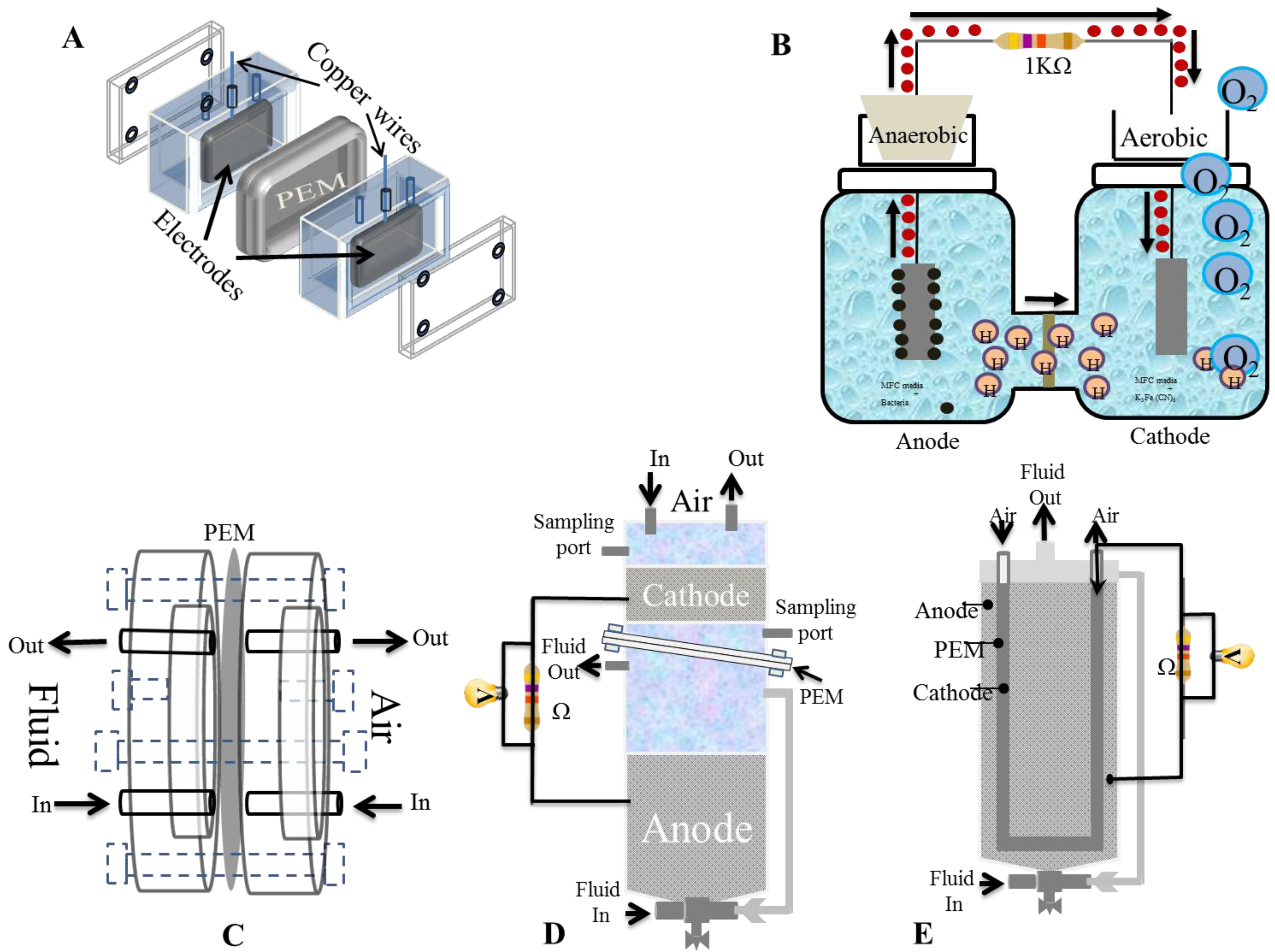
4.1. Double-Chambered Fuel Cells

In general, double-chambered fuel cells have an anodic chamber and a cathodic chamber separated by a PEM that facilitates proton transfer from the anode to the cathode while simultaneously preventing oxygen diffusion into the anode. Therefore, this configuration is commonly used to simultaneously treat wastewater and generate power. Both the anode and cathode are different compartments that are separated but also connected to each other through a proton exchange membrane (PEM) [52], which acts mainly as a proton transfer medium to complete the circuit between the two chambers (Figure 2). This completes the reaction process and prevents oxygen or the diffusion of any oxidizers from the cathode. Double-chambered fuel cells typically run in the batch mode with a chemically defined medium such as acetate or glucose solution to generate higher energy power output and can be utilized to give power in many inaccessible conditions.
In the double chamber MFC, the relatively longer distance of electrodes can decrease MFC performance due to increased internal resistance. Choi et al. demonstrated that to decrease internal resistance from 672 Ω (103 mW m−2) [53] to 93 Ω (57 mW m−2), electrodes have to be clamped along with membranes with closer electrode spacing [54]. This closer proximity of the electrode to the membrane results in higher oxygen diffusion from the cathode to anode and will directly increase both power production and power density.
Figure 3A illustrates a cubed, mini square-shaped compact flat plate MFC (FPMFC), which resembles that of a conventional chemical fuel cell having only a single electrode/PEM assembly, where the cathode is hot pressed to a Nafion PEM and is in contact with an anode to form an electrode/PEM assembly. The FPMFC with two non-conductive polycarbonate plates is bolted together. The PEM links the anodic and the cathodic chambers as shown in Figure 3A. The anodic chamber can be fed with wastewater or other organic substrates, and air can be supplied through the cathodic chamber without any catholyte, both in a continuous flow mode [55]. Nonetheless, Kim et al. have tested cube type MFCs against bottle type MFCs and found that the former produced about 14 times higher power generation (214 mWm−2 power density with 84 Ω internal resistance) than that of the latter (38 mWm−2 power density with 1272 Ω internal resistance) [56].
The miniature microbial fuel cell (mini-MFC) of about 2 cm in diameter shown in Figure 3C, provides a high volume power density of 24 and 10 mWm−2 using reticulated vitreous carbon and graphite felt electrodes, respectively, without the addition of exogenous mediators in the anolyte as reported by [20]. Therefore, they can be useful in powering self-directed sensors for long-term operations in less accessible regions. The compartments can take various practical shapes.
Upflow MFC (UMFC) configuration (Figure 3D,E) can be suitably designed to scale up to treat large volumes of wastewater and various carbon sources. He et al. employed two different UMFC configurations in their experiments. One generated a maximum power density of 170 mW m−2 with 84 Ω internal resistance (Figure 3D) [57]; the other, a power density of 29.2 W m−3 with 17.13 Ω internal resistance (Figure 3E) [58]. Since pumping fluids and recirculation are required in both configurations, it expends much greater energy than their power outputs. Therefore, the primary function of upflow configuration is wastewater treatment, not power generation. However, this configuration falls between single chambered and double chambered MFCs. They are mediators and sometimes membranes and can be used for large-scale electricity production from wastes. Nonetheless, the configuration in Figure 3E offers a low internal resistance of 4 Ω because the anode and cathode are nearby. Furthermore, one significant disadvantage of the two-chamber system is that the cathode part needs regular solution replacement with aeration to provide oxygen to the cathode [59].
Based on the basic idea of these configurations, Eom, H. et al. have proposed a new MFC system, which they named M2FC as shown in Figure 4 and consists of two compartments: A ferric-based MFC and a ferrous-based fuel cell (FC). In this reactor, a FC system, efficient regeneration of ferric ions (the catholyte in the MFC compartment) with the generation of additional electricity has been successfully accomplished. In this system, ferric ion, a cathodic triethanolamine (TEA), is converted to ferrous ion in the MFC cathode chamber, and ferrous ion, an FC fuel, is oxidized to ferric ion in the FC anode chamber. When both compartments were operated separately, depletion of the ferric ion in the catholyte was observed in about four days resulting in decreased power production. However, when combining the two units together and with continuous restocking from ferrous ions in the FC unit, the ferric ion from the ferric-based MFC unit can be continuously operated with generation of additional electricity. Moreover, the M2FC system yielded a power density of up to 2 W m−2 (over 20 times higher than the air-cathode based MFC system). Furthermore, they found that the types of catholytes and chelating agents as anolyte were found to play essential roles in the reduction of ferric ions and oxidation of ferrous ion [60].

4.2. Single-Chambered Fuel Cells
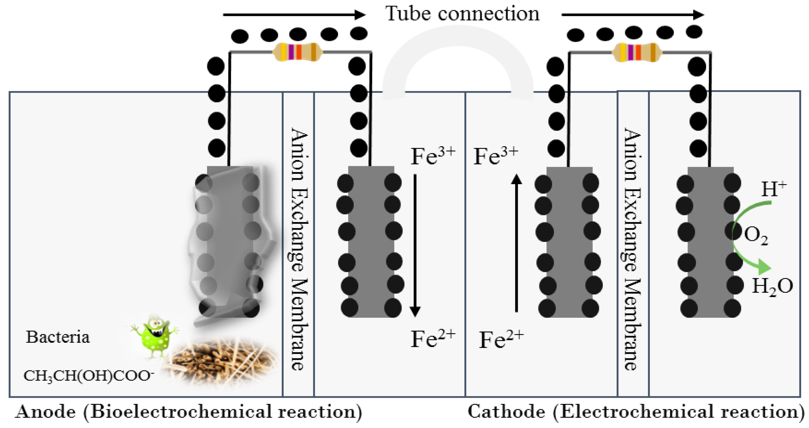
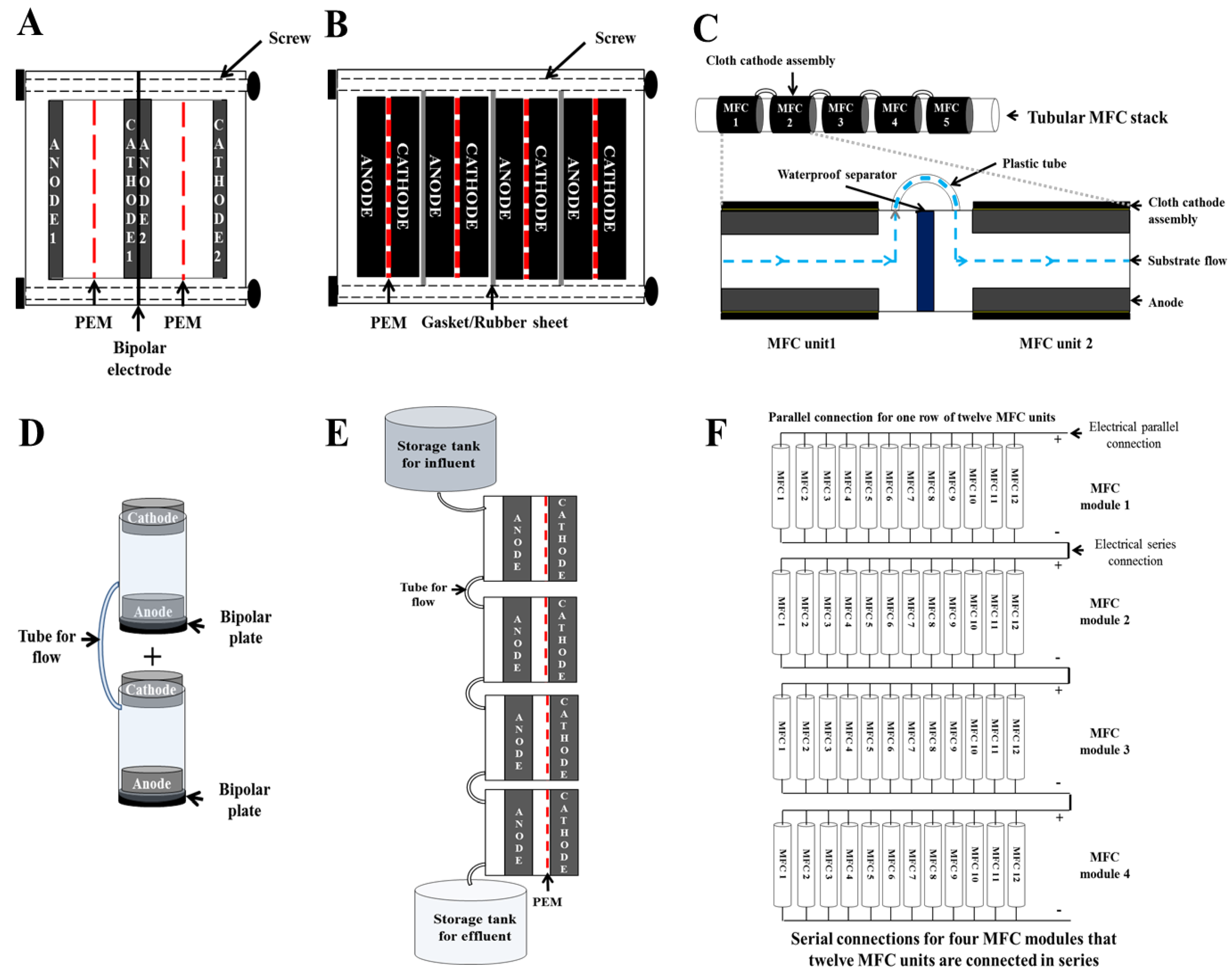
Hydrogen fuel cells consist of a cathode directly attached to a PEM allowing oxygen in the air to react directly at the electrode [59]. This principle is used for designing a single chamber MFC where the anodic chamber is linked to a porous air- exposed cathode and both are separated from each other by a gas diffusion layer (GDL) or a PEM leading to passive oxygen transfer to the cathode. Electrons are then transferred to the porous cathode through an electrically conductive wire to complete the circuit. Unnecessity to aerate the cathode when the use of the oxygen as a final electron acceptor led to the development of single chamber MFCs with air cathode assembly. This type of MFC configuration attracted researchers’ attention due to several advantages such as a decrease in internal resistance, simple operation, enhanced oxygen reduction rate on the cathode, enhanced proton diffusion, and reduced electrode spacing. Requiring less frequent regular changing of oxidative media and aeration makes this configuration more adaptable. Furthermore, Logan et al. compared a single chamber cube MFC to a bottle type MFC and found that the former produced higher power generation (2400 mW m−2 power density with 8 Ω internal resistance) than the latter (1200 mW m−2 power density with 20 Ω internal resistance) [46].
These fuel cells consist of a simple anode chamber without any definitive cathode chamber and may not contain a PEM as shown in Figure 5. Porous cathodes form one side of the cathode chamber wall using oxygen from the atmosphere and allow protons to diffuse through them. This configuration may be much easier to scale up than double-chambered fuel cells and thus has recently been utilized in research. While anodes are normal carbon electrodes, cathodes are either porous carbon electrodes, or a PEM bonded with flexible carbon cloth electrodes. However, cathodes are frequently covered with graphite in which electrolytes are poured into a steady state and behave like a catholyte, preventing the membrane and cathode from drying. In addition, water management or better fluid management poses a crucial issue in such single chambered fuel cells.
Some of the major problems of using a single chamber MFC are high oxygen diffusion, liquid leakage, and evaporation. Cheng et al. solved this problem using polytetra fluroethylene (PTFE) diffusion layers on the cathode to improve oxygen diffusion and water loss and this, in turn, improved maximum power density and columbic efficiency [61]. The single chamber MFCs reduce columbic efficiency because of prolonged oxygen diffusion into the anode.

4.3. Stacked MFC

A stacked MFC is a type of configuration in which fuel cells form a fuel cell battery by being stacked on one another in a series or parallel connection. Both connections provide power efficiently and can be utilized as a power source for a variety of practical applications.
Stacking yields higher voltage by connecting MFCs in series and more current by connecting MFCs in parallel. As a result, the required voltage, current, and power of electronic devices can be satisfied by stacking appropriately. The type of electrode, stack direction (horizontal or vertical), shape of the reactor, connection method, and modulation all affect output efficiency (Table 2).

4.3.1. Bipolar Electrode Stack

Initially, stacked MFC reactors consisted of an anode chamber, a bipolar electrode, a membrane, a cathode chamber, and end plates that were outwardly similar to a PEM fuel cell stack (Figure 6A). The bipolar electrode of a fuel cell stack has several advantages over non-bipolar fuel cells: (1) It has reliable electrical contacts, which minimize losses to resistance, (2) it minimizes iR losses (Voltage losses) in current collectors, and (3) it is easily fabricated. Shin et al. [62] used four bipolar plates for MFCs stacked in series, which resulted in a total voltage equal to the sum of the individual MFCs and no electrical degradation in performance. This bipolar stacked MFC is composed of bipolar graphite (in an H-beam shape) that has two compartments at each side (anodic and cathodic compartments), a Nafion membrane coated with a Pt/C catalyst on one side (positioned between each bipolar plate), and end plates. In another study, titanium (Ti) plates of MFC stacks could also function as both anode and cathode [63]. However, a serially-stacked bipolar MFC often reverses its voltage [63,64,65], whereby the voltage of some MFCs in the stack suddenly reverse polarity—from positive to negative—while the voltage polarity of the other MFCs remains positive. If the voltage reversal persists for a long time, carbon corrosion damages the biofilm on the anode, which causes the entire MFC system to eventually fail [66]. The compact design of a bipolar electrode MFC makes it difficult to separate the anode from the cathode [64]. In addition, even if the bipolar electrode could be separated in stacked MFCs, there is no guarantee that voltage reversal will not appear in one of the other stacked MFCs.
An et al. [65] designed a membrane-less, single-chambered MFC using a bipolar plate-electrode assembly that can easily be separated and stackable in series (Figure 6D). Such an MFC unit can be constructed with a cylindrical acrylic body, an anode (graphite felt) at the bottom, a cathode (graphite felt) at the top, and a rigid graphite plate under the anode to protect it from water leakage and air exposure. When two or more MFCs are stacked in series, the anode of each unit with a graphite plate is connected directly without external wires to the cathode of the next unit in the series. Then, when a unit of the series reverses polarity, the defective MFC can easily be detached and replaced with a new MFC. Although the bipolar electrode distributes internal resistance reduction in a stacked series, a rapid assembly and disassembly procedure would be necessary to repair voltage reversal events. An MFC stack using external metal wires, such as copper (Cu) and Ti, would be the best option for easily connecting MFC units in series (or in parallel) rather than using a bipolar electrode stack.

4.3.2. Horizontal MFC Stack

An MFC can be stacked either horizontally or vertically. Many researchers have used rectangular parallelepiped, double-chambered MFCs for horizontal stacks. Early MFC stacks were bipolar electrode MFCs stacked horizontally [62,63]. Individual MFC units of horizontally stacked MFCs (without bipolar electrodes) consist of an anode and cathode within rectangular frames that have two ports (one inlet port and one outlet port) and a PEM (or cation exchange membrane (CEM)) between the two frames (anode and cathode chambers; Figure 6B) [50,64,67,68,69,70]. These MFC units are horizontally stacked MFCs and are electrically connected to current collectors with metal wires, thus making series or parallel circuits. Rubber (or acrylic) sheets are also used as partitions in stacked MFC units so that they cannot share anolytes and/or catholytes with the other MFC units of the series. All horizontally stacked MFC units with end plates and partitioning sheets are securely fastened together with several long screws.
Based on polarization curves, Aelterman et al. [64] predicted that the maximum power density for six horizontally stacked MFC units could be as high as 308 W m−3 for series connections and 263 W m−3 for parallel connections. More recently, in a pilot project Wu et al. [50] achieved a maximum power density of 51 W m−3 and a chemical oxygen demand (COD) removal efficiency of 97% from a their scaled-up, 72 L, rectangular, horizontal-stacked parallel-connected MFC. Over a six-month period, Vilajeliu-Pons et al. [67] obtained a power density of between 2 and 4 W m–3 using six-stacked 115 L MFCs (in a combination of series and parallel connections) using swine manure as an energy substrate.
Zhuang and Zhou [71] constructed a tubular, air-cathode horizontally-stacked MFC (void volume 0.75 L) using tubular polyvinyl chloride (PCV), which served as the frame for the anode chamber and a tubular cathode membrane assembly formed by hot-pressing carbon fiber cloth to a CEM. Titanium wires were used to serially connect the cells. This design allowed the substrate (food) to flow hydraulically between the anode chambers and thus could be adapted as a drainpipe in wastewater treatment processes. Similarly, Zhuang et al. [72] constructed a 10-L, serpentine-type MFC series stack using forty tubular air-cathode MFC units (Figure 6C). After operating the unit for 180 days with brewery wastewater, they obtained an open-circuit voltage (OCV) of 23.0 V and maximum power density of 4.1 W m−3. They concluded that this serpentine-type air-cathode MFC stack could be applied to wastewater treatment processes because it is inexpensive to construct, easy to modulate, can be scaled up easily, and possesses an uncomplicated wastewater distribution system. However, when continuously operated, each MFC unit would possess different electrical performance due to differences in their concentrations of organic matter and ion conductivity on the anode side of the biofilm of each unit [73]. Low COD concentration near the end of an MFC unit can reduce electrical performance or even produce negligible power relative to the MFC nearest the inlet. In long-term operation, organic matter depleted near one end of an MFC could result in an extreme loss of power and ultimately complete failure due to inactivated microorganisms in the biofilm. In addition, when multiple MFC units are connected in series, voltage reversal could occur due to an imbalance in substrate loading, causing a kinetic disparity between MFC units or between the anode and cathode [74].

4.3.3. Vertical MFC Stack

A vertical, cascade-stacked MFC system (Figure 6E) can also be detrimentally impacted by voltage reversal events due to substrate imbalances. However, this type of MFC system is inexpensive to operate because the fluid flow of electrolytes is mostly gravity driven (no pumps required), whereas horizontally stacked MFCs usually require pumps to supply substrate (e.g., wastewater) to microbes in the anode chamber and to supply oxidized catholytes (i.e., an air-saturated solution for the reduction reaction) to the cathode chamber. The first self-sustainable MFC stack capable of self-maintenance used a vertical, single-chambered MFC cascade consisting of 40 identical 20 mL units (total volume of 0.8 L) [75]. Feeding, hydration, sensing, and reporting were performed by the MFC stack. In fact, the MFC stack produced net excess energy. In addition, when six of these stacks were connected in parallel as a continuous-flow cascade, the stacks removed >95% of COD from artificial wastewater (containing 5 mM acetate) over a 5.7 h period [76]. Recently, a smartphone was successfully charged by a scaled-up MFC cascade (10.5 L stack volume) using urine as a substrate [77]. Even so, the 3 h charge from this MFC stack could power a 1.75 h cell phone call. However, the power produced by this MFC stack was low (110 mW with maximum power density of ~10 W m−3). Therefore, a number of factors must be considered when determining if a vertical cascade MFC is capable of both generating enough power and sufficiently treating wastewater: (1) The method required for maintaining the substrate flow rate (gravity-fed vs. pumps), (2) the height of the MFC system if it is gravity-fed, (3) whether organic concentrations are likely to decline near one end of the MFC, and (4) the volume of the reactor.

5. Scalability of MFC

The MFCs scalability depends not only on how efficiently it uses fuel and its capacity, but also on how much electrical power it can generate. The primary challenge in scaling-up an MFC system is how to attain adequate energy production using a reasonable volume of reactor liquid. Before commercializing MFCs, bioreactors and the processes associated with it have to be successfully scaled-up as a large scale-up, not simply a pilot scale-up. This requires much higher volume bioreactors. However, volumetric power generation decreases proportionally (power/unit volume) as the volume of an MFC increases. The multiple miniaturized MFC stacking would be followed for scale-up [81]. Recently, the modularization of multiple miniaturized MFCs and subsequent stacking has been developed for scale-up for reducing power or voltage loss.

5.1. Modular MFC Stack Systems with Multiple Electrodes

To avoid ionic cross-conduction, which causes voltage reversal in serially-connected, stacked MFCs, an MFC’s electrolytes must be separated from other MFCs’ electrolytes by rubber sheets [64] and bipolar plates [62,63,65]. Although electrolytes are slightly shared when multiple series-connected MFCs have sequential-flow, the use of thin, inter-connecting tubes [72] and an overflow method [51] could prevent voltage reversal by reducing ionic cross-conduction. Ionic cross-conduction occurs when the same electrolyte (anolyte or catholyte) is shared by two different MFCs in a connected series [71]. Separating MFC reactors would require additional material, which would increase reactor complexity, construction costs, and maintenance. However, a module MFC stack system would be more efficient and less expensive to construct.
He et al. [47] developed a stackable MFC with an anode and dual-cathode module, which is both easy to construct and easy to access to maintain the electrodes. The highest power density achieved with this module system was 11.0 W m−3 (using raw domestic wastewater). A later iteration of the system used a larger MFC module (6.1 L) with four anode modules and three cathode modules, which together provided a maximum power density of 6.0 W m−3 and COD removal of between 40% to 60% [82]. However, the researchers did not reveal the results of the study on the MFC stack with electrical series and a parallel connection.
A promising new design for a modular MFC stack has both serially-connected and parallel-connected electrical arrays. In this arrangement, the MFC units of a module are connected in parallel first to prevent voltage reversal and also to increase the current. Using this approach, Feng et al. [80] showed that a high current (0.435 A) could be obtained by using a modular MFC stack connected in parallel with thirty-two carbon brush anodes. After the parallel-connected module units are connected in series, high voltage and power can be obtained with the required standard input voltage for electrical devices (over 1.5 V). The power of such electrical devices depends on how many MFCs are connected together. Ge and He [83] developed a 200 L modular MFC stack, which generated ~200 mW of power. This MFC system was comprised of eight MFC modules containing 12 tubular MFC units (2 L per unit). The 12 MFC units were first connected in parallel (using external wires). Then, they connected the eight MFC modules in series (Figure 6F). Ge and He avoided short-circuiting the connection between MFC modules by hydraulically connecting two modules: The hydraulic connection was designed to feed wastewater to the modules. This system achieved a removal efficiency of >75% for COD, 90% for suspended solids, and 68% for ammonia nitrogen.

5.2. Outlook for MFC Scale-Up

Scaling-up from a bench-scale bioreactor to a reactor holding a thousand liters of liquid is difficult [84,85,86]. Besides the technical problems that have to be addressed, one must consider operational complexities, logistical support, utility supplies, and regulatory and safety compliance regulations. The major obstacles that also prevent MFCs from competing effectively with conventional wastewater treatment processes include their inadequate cathodic electron transfer capacity, lower coulombic efficiency (CE), lower power production, and relatively high capital cost [87]. The problem is that researchers have limited information about all these constraints, yet must integrate many different potential approaches and tailor them to either a specific or general situation. However, sustained progress and continued research should allow use of an MFC in a scaled-up commercial system for simultaneous electricity generation and wastewater treatment within the near future.

6. Conclusions

This review highlights the history of the microbial fuel cell and progress in developing the concept of the MFC, its major elements and their importance, the significance of MFC design and configuration and their impact on overall performance, and the scalability of the MFC with attendant challenges and limitations. Considerable developments in mediator-less MFC systems have been seen in the last two decades, although critical challenges for scale-up and its application still exist impeding MFC commercialization. Minimizing energy loss (e.g., overpotential and voltage loss) while maximizing pollutants removal is vital in the scale-up of an MFC system. Multiplication and miniaturization of MFC systems are essential to reduce energy loss for scaling-up an MFC using stack methods. A stacked MFC (in series connection) is associated with the phenomenon of voltage reversal causing MFC failure. The type of electrode, stack direction (horizontal or vertical), shape of the single reactor, connection method, and modulation need to be carefully considered and chosen to achieve the best stacked MFC performance and prevent voltage reversal. Improving these technical demands must precede making economically feasible large-scale multiple-miniaturized MFCs a reality, as stacked operations have yet to be conducted over a 1 m3 scale. Further research will suggest reasonable reactor volume and design for the multiple-miniaturized MFCs to efficiently generate energy.

Author Contributions

Conceptualization, S.G.A.F., T.K., and S.-E.O.; investigation, S.G.A.F. and T.K.; data-curation, S.G.A.F. and T.K.; writing-original draft preparation, S.G.A.F. and T.K.; writing-review and editing, I.M.I.I., T.K., and S.-E.O.; supervision, T.K. and S.-E.O.; project administration, S.-E.O.; funding acquisition, S.-E.O.

Funding

This research was funded by [Ministry of Education], grant number NRF-2017R1D1A1A09000676.

Acknowledgments

This research was supported by Basic Science Research Program through the National Research Foundation of Korea (NRF) funded by the Ministry of Education (NRF-2017R1D1A1A09000676).

Conflicts of Interest

The authors declare no conflict of interest.

References

  1. Bishoge, O.; Zhang, L.; Mushi, W. The Potential Renewable Energy for Sustainable Development in Tanzania: A Review. Clean Technol. 2018, 1, 70–88. [Google Scholar] [CrossRef] [Green Version]
  2. Bond, D.R.; Lovley, D.R. Electricity Production by Geobacter sulfurreducens Attached to Electrodes. Appl. Environ. Microbiol. 2003, 69, 1548–1555. [Google Scholar] [CrossRef] [PubMed]
  3. Bose, D.; Kandpal, V.; Dhawan, H.; Vijay, P.; Gopinath, M. Energy Recovery with Microbial Fuel Cells: Bioremediation and Bioelectricity. In Waste Bioremediation; Varjani, S.J., Gnansounou, E., Gurunathan, B., Pant, D., Zakaria, Z.A., Eds.; Springer: Singapore, 2018; pp. 7–33. [Google Scholar]
  4. Aghababaie, M.; Farhadian, M.; Jeihanipour, A.; Biria, D. Effective factors on the performance of microbial fuel cells in wastewater treatment—A review. Environ. Technol. Rev. 2015, 4, 71–89. [Google Scholar] [CrossRef]
  5. Galvani, L. De viribus electricitatis in motu musculari. Commentarius. Bonoiensi Sci. Artium Intituo Acad. Comment. 1791, 7, 363–418. [Google Scholar]
  6. Grove, W.R. LVI. On a new voltaic combination: To the editors of the Philosophical Magazine and Journal. Lond. Edinb. Dublin Philos. Mag. J. Sci. 1838, 13, 430–431. [Google Scholar] [CrossRef]
  7. Potter, M.C. Bacteria as Agents in the Oxidation of Amorphous Carbon. Proc. R. Soc. Lond. Ser. B Contain. Papers Biol. Character 1908, 80, 239–259. [Google Scholar] [CrossRef]
  8. Potter, M.C. Electrical effects accompanying the decomposition of organic compounds. Proc. R. Soc. Lond. B Biol. Sci. 1911, 84, 260–276. [Google Scholar] [CrossRef]
  9. Cohen, B. The bacterial culture as an electrical half-cellJournal of Bacteriology. J. Bacteriol. 1931, 21, 18–19. [Google Scholar]
  10. Rohrback, G.H.; Scott, W.R.; Canfield, J.H. Biochemical fuel cells. Biol. Fuel Cells Appl. 1962, 19, 18. [Google Scholar]
  11. Williams, K.R. An Introduction to Fuel Cells; Elsevier: Amsterdam, The Netherlands, 1966. [Google Scholar]
  12. Allen, R.M.; Bennetto, H.P. Microbial Fuel-Cells: Electricity production from carbohydrates. Appl. Biochem. Biotechnol. 1993, 39, 27–40. [Google Scholar] [CrossRef]
  13. Kim, B.H.; Kim, H.J.; Hyun, M.S.; Park, D.H. Direct electrode reaction of Fe(III)-reducing bacterium, Shewanella putrefaciens. J. Microbiol. Biotechnol. 1999, 9, 127–131. [Google Scholar]
  14. Du, Z.; Li, H.; Gu, T. A state of the art review on microbial fuel cells: A promising technology for wastewater treatment and bioenergy. Biotechnol. Adv. 2007, 25, 464–482. [Google Scholar] [CrossRef] [PubMed]
  15. Ucar, D.; Zhang, Y.; Angelidaki, I. An Overview of Electron Acceptors in Microbial Fuel Cells. Front. Microbiol. 2017, 8, 643. [Google Scholar] [CrossRef] [PubMed] [Green Version]
  16. Katz, E.; Shipway, A.N.; Willner, I. Biochemical fuel cells. In Handbook of Fuel Cells; John Wiley & Sons, Ltd.: Chichester, West Sussex, UK, 2010. [Google Scholar]
  17. Rahimnejad, M.; Adhami, A.; Darvari, S.; Zirepour, A.; Oh, S.-E. Microbial fuel cell as new technology for bioelectricity generation: A review. Alex. Eng. J. 2015, 54, 745–756. [Google Scholar] [CrossRef] [Green Version]
  18. Bennetto, H.P.; Stirling, J.L.; Tanaka, K.; Vega, C.A. Anodic reactions in microbial fuel cells. Biotechnol. Bioeng. 1983, 25, 559–568. [Google Scholar] [CrossRef]
  19. Kim, H.J.; Park, H.S.; Hyun, M.S.; Chang, I.S.; Kim, M.; Kim, B.H. A mediator-less microbial fuel cell using a metal reducing bacterium, Shewanella putrefaciens. Enzyme Microb. Technol. 2002, 30, 145–152. [Google Scholar] [CrossRef]
  20. Ringeisen, B.R.; Henderson, E.; Wu, P.K.; Pietron, J.; Ray, R.; Little, B.; Biffinger, J.C.; Jones-Meehan, J.M. High Power Density from a Miniature Microbial Fuel Cell Using Shewanella oneidensis DSP10. Environ. Sci. Technol. 2006, 40, 2629–2634. [Google Scholar] [CrossRef]
  21. Kim, B.; Ikeda, T.; Park, H.; Kim, H.; Hyun, M.; Kano, K.; Takagi, K.; Tatsumi, H. Electrochemical activity of an Fe(III)-reducing bacterium, Shewanella putrefaciens IR-1, in the presence of alternative electron acceptors. Biotechnol. Tech. 1999, 13, 475–478. [Google Scholar] [CrossRef]
  22. Kumar, R.; Singh, L.; Wahid, Z.A.; Din, M.F.M. Exoelectrogens in microbial fuel cells toward bioelectricity generation: A review. Int. J. Energy Res. 2015, 39, 1048–1067. [Google Scholar] [CrossRef]
  23. Chaudhuri, S.K.; Lovley, D.R. Electricity generation by direct oxidation of glucose in mediatorless microbial fuel cells. Nat. Biotechnol. 2003, 21, 1229–1232. [Google Scholar] [CrossRef]
  24. Pham, C.A.; Jung, S.J.; Phung, N.T.; Lee, J.; Chang, I.S.; Kim, B.H.; Yi, H.; Chun, J. A novel electrochemically active and Fe(III)-reducing bacterium phylogenetically related to Aeromonas hydrophila, isolated from a microbial fuel cell. FEMS Microbiol. Lett. 2003, 223, 129–134. [Google Scholar] [CrossRef]
  25. Zhang, L.; Zhou, S.; Zhuang, L.; Li, W.; Zhang, J.; Lu, N.; Deng, L. Microbial fuel cell based on Klebsiella pneumoniae biofilm. Electrochem. Commun. 2008, 10, 1641–1643. [Google Scholar] [CrossRef]
  26. Fan, L.P.; Xue, S. Overview on Electricigens for Microbial Fuel Cell. Open Biotechnol. J. 2016, 10, 398–406. [Google Scholar] [CrossRef] [Green Version]
  27. Gil, G.-C.; Chang, I.-S.; Kim, B.H.; Kim, M.; Jang, J.-K.; Park, H.S.; Kim, H.J. Operational parameters affecting the performannce of a mediator-less microbial fuel cell. Biosens. Bioelectron. 2003, 18, 327–334. [Google Scholar] [CrossRef]
  28. Barua, P.K.; Deka, D. Electricity Generation from Biowaste Based Microbial Fuel Cells. Int. J. Energy 2010, 1, 77–92. [Google Scholar]
  29. Hamelers, H.M.; Ter Heijne, A.; Sleutels, T.J.A.; Jeremiasse, A.; Strik, D.B.T.B.; Buisman, C.N. New applications and performance of bioelectrochemical systems. Appl. Microbiol. Biotechnol. 2010, 85, 1673–1685. [Google Scholar] [CrossRef] [PubMed]
  30. Cheng, S.; Liu, H.; Logan, B.E. Power Densities Using Different Cathode Catalysts (Pt and CoTMPP) and Polymer Binders (Nafion and PTFE) in Single Chamber Microbial Fuel Cells. Environ. Sci. Technol. 2006, 40, 364–369. [Google Scholar] [CrossRef]
  31. Dombrovskis, J.K.; Palmqvist, A.E.C. Recent Progress in Synthesis, Characterization and Evaluation of Non-Precious Metal Catalysts for the Oxygen Reduction Reaction. Fuel Cells 2016, 16, 4–22. [Google Scholar] [CrossRef]
  32. Rahimnejad, M.; Jafary, T.; Najafpour, G.; Ghoreyshi, A.A. Effect of Glucose Concentration on Performance of Microbial Fuel Cell. In Proceedings of the International Conference on Environmental Research and Technology, Penang, Malaysia, 2–4 June 2010; pp. 236–240. [Google Scholar]
  33. Khater, D.Z.; El-Khatib, K.M.; Hassan, H.M. Microbial diversity structure in acetate single chamber microbial fuel cell for electricity generation. J. Genet. Eng. Biotechnol. 2017, 15, 127–137. [Google Scholar] [CrossRef]
  34. Kim, J.R.; Jung, S.H.; Regan, J.M.; Logan, B.E. Electricity generation and microbial community analysis of alcohol powered microbial fuel cells. Bioresour. Technol. 2007, 98, 2568–2577. [Google Scholar] [CrossRef]
  35. Liu, Y.; Dong, S. A biofuel cell with enhanced power output by grape juice. Electrochem. Commun. 2007, 9, 1423–1427. [Google Scholar] [CrossRef]
  36. Tatinclaux, M.; Gregoire, K.; Leininger, A.; Biffinger, J.C.; Tender, L.; Ramirez, M.; Torrents, A.; Kjellerup, B.V. Electricity generation from wastewater using a floating air cathode microbial fuel cell. Water Energy Nexus 2018, 1, 97–103. [Google Scholar] [CrossRef]
  37. Patil, S.A.; Surakasi, V.P.; Koul, S.; Ijmulwar, S.; Vivek, A.; Shouche, Y.S.; Kapadnis, B.P. Electricity generation using chocolate industry wastewater and its treatment in activated sludge based microbial fuel cell and analysis of developed microbial community in the anode chamber. Bioresour. Technol. 2009, 100, 5132–5139. [Google Scholar] [CrossRef] [PubMed]
  38. Oh, S.; Logan, B.E. Hydrogen and electricity production from a food processing wastewater using fermentation and microbial fuel cell technologies. Water Res. 2005, 39, 4673–4682. [Google Scholar] [CrossRef] [PubMed]
  39. Wen, Q.; Wu, Y.; Cao, D.; Zhao, L.; Sun, Q. Electricity generation and modeling of microbial fuel cell from continuous beer brewery wastewater. Bioresour. Technol. 2009, 100, 4171–4175. [Google Scholar] [CrossRef] [PubMed]
  40. Jiang, J.; Zhao, Q.; Zhang, J.; Zhang, G.; Lee, D.-J. Electricity generation from bio-treatment of sewage sludge with microbial fuel cell. Bioresour. Technol. 2009, 100, 5808–5812. [Google Scholar] [CrossRef] [PubMed]
  41. Cercado-Quezada, B.; Delia, M.-L.; Bergel, A. Testing various food-industry wastes for electricity production in microbial fuel cell. Bioresour. Technol. 2010, 101, 2748–2754. [Google Scholar] [CrossRef] [PubMed] [Green Version]
  42. Flimban, S.G.A.; Hassan, S.H.A.; Rahman, M.M.; Oh, S.-E. The effect of Nafion membrane fouling on the power generation of a microbial fuel cell. Int. J. Hydrogen Energy 2018. [Google Scholar] [CrossRef]
  43. Kondaveeti, S.; Lee, J.; Kakarla, R.; Kim, H.S.; Min, B. Low-cost separators for enhanced power production and field application of MFCs (MFCs). Electrochim. Acta 2014, 132, 434–440. [Google Scholar] [CrossRef]
  44. Call, D.; Logan, B.E. Hydrogen Production in a Single Chamber Microbial Electrolysis Cell Lacking a Membrane. Environ. Sci. Technol. 2008, 42, 3401–3406. [Google Scholar] [CrossRef]
  45. Pant, D.; Bogaert, G.V.; Diels, L.; Vanbroekhoven, K. A review of the substrates used in microbial fuel cells (MFCs) for sustainable energy production. Bioressour. Technol. 2010, 101, 1533–1543. [Google Scholar] [CrossRef] [PubMed]
  46. Logan, B.; Cheng, S.; Watson, V.; Estadt, G. Graphite Fiber Brush Anodes for Increased Power Production in Air-Cathode Microbial Fuel Cells. Environ. Sci. Technol. 2007, 41, 3341–3346. [Google Scholar] [CrossRef] [PubMed]
  47. He, W.; Zhang, X.; Liu, J.; Zhu, X.; Feng, Y.; Logan, B.E. Microbial fuel cells with an integrated spacer and separate anode and cathode modules. Environ. Sci. 2016, 2, 186–195. [Google Scholar] [CrossRef]
  48. You, S.; Zhao, Q.; Zhang, J.; Jiang, J.; Zhao, S. A microbial fuel cell using permanganate as the cathodic electron acceptor. J. Power Sources 2006, 162, 1409–1415. [Google Scholar] [CrossRef]
  49. Rabaey, K.; Boon, N.; Siciliano, S.D.; Verhaege, M.; Verstraete, W. Biofuel Cells Select for Microbial Consortia That Self-Mediate Electron Transfer. Appl. Environ. Microbiol. 2004, 70, 5373–5382. [Google Scholar] [CrossRef] [Green Version]
  50. Wu, S.; Li, H.; Zhou, X.; Liang, P.; Zhang, X.; Jiang, Y.; Huang, X. A novel pilot-scale stacked microbial fuel cell for efficient electricity generation and wastewater treatment. Water Res. 2016, 98, 396–403. [Google Scholar] [CrossRef] [PubMed]
  51. Tremouli, A.; Greenman, J.; Ieropoulos, I. Investigation of ceramic MFC stacks for urine energy extraction. Bioelectrochemistry 2018, 123, 19–25. [Google Scholar] [CrossRef] [Green Version]
  52. Asensio, Y.; Montes, I.B.; Fernandez-Marchante, C.M.; Lobato, J.; Cañizares, P.; Rodrigo, M.A. Selection of cheap electrodes for two-compartment microbial fuel cells. J. Electroanal. Chem. 2017, 785 (Suppl. C), 235–240. [Google Scholar] [CrossRef]
  53. Sun, J.; Hu, Y.; Bi, Z.; Cao, Y. Improved performance of air-cathode single-chamber MFC for wastewater treatment using microfiltration membranes and multiple sludge inoculation. J. Power Sources 2009, 187, 471–479. [Google Scholar] [CrossRef]
  54. Choi, S.; Kim, J.R.; Cha, J.; Kim, Y.; Premier, G.C.; Kim, C. Enhanced power production of a membrane electrode assembly MFC (MFC) using a cost effective poly[2,5-benzimidazole] (ABPBI) impregnated non-woven fabric filter. Bioresour. Technol. 2013, 128, 14–21. [Google Scholar] [CrossRef]
  55. Min, B.; Logan, B.E. Continuous Electricity Generation from Domestic Wastewater and Organic Substrates in a Flat Plate Microbial Fuel Cell. Environ. Sci. Technol. 2004, 38, 5809–5814. [Google Scholar] [CrossRef] [PubMed]
  56. Kim, J.R.; Cheng, S.; Oh, S.-E.; Logan, B.E. Power generation using different cation, anion, and ultrafiltration membranes in MFCs. Environ. Sci. Technol. 2007, 41, 1004–1009. [Google Scholar] [CrossRef] [PubMed]
  57. He, Z.; Minteer, S.D.; Angenent, L.T. Electricity Generation from Artificial Wastewater Using an Upflow Microbial Fuel Cell. Environ. Sci. Technol. 2005, 39, 5262–5267. [Google Scholar] [CrossRef] [PubMed]
  58. He, Z.; Wagner, N.; Minteer, S.D.; Angenent, L.T. An Upflow Microbial Fuel Cell with an Interior Cathode:  Assessment of the Internal Resistance by Impedance Spectroscopy. Environ. Sci. Technol. 2006, 40, 5212–5217. [Google Scholar] [CrossRef] [PubMed]
  59. Liu, H.; Logan, B.E. Electricity Generation Using an Air-Cathode Single Chamber Microbial Fuel Cell in the Presence and Absence of a Proton Exchange Membrane. Environ. Sci. Technol. 2004, 38, 4040–4046. [Google Scholar] [CrossRef] [PubMed]
  60. Eom, H.; Chung, K.; Kim, I.; Han, J.I. Development of a hybrid microbial fuel cell (MFC) and fuel cell (FC) system for improved cathodic efficiency and sustainability: The M2FC reactor. Chemosphere 2011, 85, 672–676. [Google Scholar] [CrossRef] [PubMed]
  61. Cheng, S.; Liu, H.; Logan, B.E. Increased performance of single-chamber MFCs using an improved cathode structure. Electrochem. Commun. 2006, 8, 489–494. [Google Scholar] [CrossRef]
  62. Shin, S.H.; Choi, Y.J.; Na, S.H.; Jung, S.H.; Kim, S.H. Development of bipolar plate stack type microbial fuel cells. Bull. Korean Chem. Soc. 2006, 27, 281–285. [Google Scholar]
  63. Dekker, A.; Heijne, A.T.; Saakes, M.; Hamelers, H.V.; Buisman, C.J. Analysis and improvement of a scaled-up and stacked microbial fuel cell. Environ. Sci. Technol. 2009, 43, 9038–9042. [Google Scholar] [CrossRef]
  64. Aelterman, P.; Rabaey, K.; Pham, H.T.; Boon, N.; Verstraete, W. Continuous electricity generation at high voltages and currents using stacked microbial fuel cells. Environ. Sci. Technol. 2006, 40, 3388–3394. [Google Scholar] [CrossRef]
  65. An, J.; Kim, B.; Jang, J.K.; Lee, H.-S.; Chang, I.S. New architecture for modulization of membraneless and single-chambered microbial fuel cell using a bipolar plate-electrode assembly (BEA). Biosens. Bioelectron. 2014, 59, 28–34. [Google Scholar] [CrossRef] [PubMed]
  66. Li, J.; Li, H.; Fu, Q.; Liao, Q.; Zhu, X.; Kobayashi, H.; Ye, D. Voltage reversal causes bioanode corrosion in microbial fuel cell stacks. Int. J. Hydrogen Energy 2017, 42, 27649–27656. [Google Scholar] [CrossRef]
  67. Vilajeliu-Pons, A.; Puig, S.; Salcedo-Dávila, I.; Balaguer, M.; Colprim, J. Long-term assessment of six-stacked scaled-up MFCs treating swine manure with different electrode materials. Environ. Sci. 2017, 3, 947–959. [Google Scholar] [CrossRef] [Green Version]
  68. Rahimnejad, M.; Ghoreyshi, A.A.; Najafpour, G.; Younesi, H.; Shakeri, M. A novel microbial fuel cell stack for continuous production of clean energy. Int. J. Hydrogen Energy 2012, 37, 5992–6000. [Google Scholar] [CrossRef]
  69. Jafary, T.; Rahimnejad, M.; Ghoreyshi, A.A.; Najafpour, G.; Hghparast, F.; Daud, W.R.W. Assessment of bioelectricity production in microbial fuel cells through series and parallel connections. Energy Convers. Manag. 2013, 75, 256–262. [Google Scholar] [CrossRef]
  70. Zhang, L.; Li, J.; Zhu, X.; Ye, D.-d.; Fu, Q.; Liao, Q. Response of stacked microbial fuel cells with serpentine flow fields to variable operating conditions. Int. J. Hydrogen Energy 2017, 42, 27641–27648. [Google Scholar] [CrossRef]
  71. Zhuang, L.; Zhou, S. Substrate cross-conduction effect on the performance of serially connected microbial fuel cell stack. Electrochem. Commun. 2009, 11, 937–940. [Google Scholar] [CrossRef]
  72. Zhuang, L.; Yuan, Y.; Wang, Y.; Zhou, S. Long-term evaluation of a 10-liter serpentine-type microbial fuel cell stack treating brewery wastewater. Bioresour. Technol. 2012, 123, 406–412. [Google Scholar] [CrossRef]
  73. Gurung, A.; Kim, J.; Jung, S.; Jeon, B.-H.; Yang, J.E.; Oh, S.-E. Effects of substrate concentrations on performance of serially connected microbial fuel cells (MFCs) operated in a continuous mode. Biotechnol. Lett. 2012, 34, 1833–1839. [Google Scholar] [CrossRef]
  74. An, J.; Sim, J.; Lee, H.-S. Control of voltage reversal in serially stacked microbial fuel cells through manipulating current: Significance of critical current density. J. Power Sources 2015, 283, 19–23. [Google Scholar] [CrossRef]
  75. Ledezma, P.; Stinchcombe, A.; Greenman, J.; Ieropoulos, I. The first self-sustainable microbial fuel cell stack. Phys. Chem. Chem. Phys. 2013, 15, 2278–2281. [Google Scholar] [CrossRef] [PubMed]
  76. Ledezma, P.; Greenman, J.; Ieropoulos, I. MFC-cascade stacks maximise COD reduction and avoid voltage reversal under adverse conditions. Bioresour. Technol. 2013, 134, 158–165. [Google Scholar] [CrossRef] [PubMed]
  77. Walter, X.A.; Stinchcombe, A.; Greenman, J.; Ieropoulos, I. Urine transduction to usable energy: A modular MFC approach for smartphone and remote system charging. Appl. Energy 2017, 192, 575–581. [Google Scholar] [CrossRef]
  78. Ieropoulos, I.; Greenman, J.; Melhuish, C. Microbial fuel cells based on carbon veil electrodes: Stack configuration and scalability. Int. J. Energy Res. 2008, 32, 1228–1240. [Google Scholar] [CrossRef]
  79. Zhuang, L.; Zheng, Y.; Zhou, S.; Yuan, Y.; Yuan, H.; Chen, Y. Scalable microbial fuel cell (MFC) stack for continuous real wastewater treatment. Bioresour. Technol. 2012, 106, 82–88. [Google Scholar] [CrossRef]
  80. Feng, Y.; He, W.; Liu, J.; Wang, X.; Qu, Y.; Ren, N. A horizontal plug flow and stackable pilot microbial fuel cell for municipal wastewater treatment. Bioresour. Technol. 2014, 156, 132–138. [Google Scholar] [CrossRef] [PubMed]
  81. Mateo, S.; Cantone, A.; Cañizares, P.; Fernández-Morales, F.J.; Scialdone, O.; Rodrigo, M.A. On the staking of miniaturized air-breathing microbial fuel cells. Appl. Energy 2018, 232, 1–8. [Google Scholar] [CrossRef]
  82. He, W.; Wallack, M.J.; Kim, K.-Y.; Zhang, X.; Yang, W.; Zhu, X.; Feng, Y.; Logan, B.E. The effect of flow modes and electrode combinations on the performance of a multiple module microbial fuel cell installed at wastewater treatment plant. Water Res. 2016, 105, 351–360. [Google Scholar] [CrossRef]
  83. Ge, Z.; He, Z. Long-term performance of a 200 liter modularized microbial fuel cell system treating municipal wastewater: Treatment, energy, and cost. Environ. Sci. Water Res. Technol. 2016, 2, 274–281. [Google Scholar] [CrossRef]
  84. Janicek, A.; Fan, Y.; Liu, H. Design of microbial fuel cells for practical application: A review and analysis of scale-up studies. Biofuels 2014, 5, 79–92. [Google Scholar] [CrossRef]
  85. Logan, B. Scaling up microbial fuel cells and other bioelectrochemical systems. Appl. Microbiol. Biotechnol. 2010, 85, 1665–1671. [Google Scholar] [CrossRef] [PubMed]
  86. Ghadge, A.N.; Jadhav, D.A.; Ghangrekar, M.M. Wastewater treatment in pilot-scale microbial fuel cell using multi-electrode assembly with ceramic separator suitable for field applications. Environ. Prog. Sustain. Energy 2016, 35, 1809–1817. [Google Scholar] [CrossRef]
  87. Jadhav, D.A.; Ghadge, A.N.; Ghangrekar, M.M. Simultaneous organic matter removal and disinfection of wastewater with enhanced power generation in microbial fuel cell. Bioresour. Technol. 2014, 163, 328–334. [Google Scholar] [CrossRef] [PubMed]
Figure 1. History of discovery of bioelectrochemical systems.
Energies 12 03390 g001
Figure 2. Major elements of an microbial fuel cell (MFC) reactor: 1. A proton exchange membrane separating the two chambers; 2. Anode chamber (anaerobic conditions); 3. Cathode chamber (aerobic conditions); 4. Substrate for microorganisms metabolism; 5. Pure or mixed bacterial cultures (a) and biofilm (b); 6. Nitrogen gas (N2) to maintain an anaerobic condition; 7. Anode electrode, on which bacterial attachment occurs; 8. Copper wire for transferring electrons from the anode to the cathode; 9. Ω resistor; 10. Cathode electrode to accept the electrons from the anode; 11. Oxygen or air; and 12. Electrons reducing agent (modified from [42]).
Energies 12 03390 g002
Figure 3. Schematic design of microbial fuel cell configuration.
Energies 12 03390 g003
Figure 4. Schematic design of M2FC configuration.
Energies 12 03390 g004
Figure 5. Single chamber microbial fuel cell.
Energies 12 03390 g005
Figure 6. Schematic diagrams of stacked MFCs. (A) a bipolar plated, double-chambered MFC horizontal stack; (B) double-chambered MFC horizontal stack; (C) a tubular, air-cathode MFC horizontal stack; (D) a tubular, bipolar, plate membrane-less, double-chambered MFC vertical stack; (E) a cascade, air-cathode MFC vertical stack; and (F) a module MFC stack with both serial and parallel connections.
Energies 12 03390 g006
Table 1. MFC performance relative to configuration.
TypesSubstratesElectrodeElectron AcceptorPower DensityRef.
AnodeCathode
Single chamberGlucoseGraphite carbon fiber brushPt (30%) coated carbon clothOxygen2.4 W m−2[46]
Single chamberAcetate-amended WastewaterGraphite fiber brushActivated carbon catalyst on Stainless steel meshOxygen1.1 W m−2[47]
Double chamberGlucoseCarbon paperCarbone clothPermanganate0.12 W m−2[48]
Double chamberGlucoseGraphite plateGraphite plateHexacynoferrate4.3 W m−2[49]
StackedSodium acetateGranular activated carbonGranular activated carbonOxygen50.9 W m−3[50]
StackedNeat undiluted urineUntreated carbon fiber veilCoating activated carbon paste on polytetrafluooethyleneOxygen0.8 W m−3[51]
Table 2. Summary of configuration, operational condition, and performance of MFC stacks reported in the literature.
ConfigurationNo. of Reactors Total Volume (L)ElectrodeConnectionInternal Resistance (Ω)OCV (V)Maximum Power Density (W m−3)Maximum Current Density (A m−3)Organic conc. or OLRRef.
Two-chamber MFC stack60.936Graphite granulesCu wire6.5 (s) 1)4.16 (s)
0.67 (p)
308 (s)
263 (p) 2)
0.085 A (s)
0.425 A (p)
1.62 g COD L−1 d−1[64]
Bipolar two-chamber MFC stack420Ti platesTi plates1.2 mΩ m−3 (s)4.06 (s)144 (s)2.8 A m−2-[63]
Two-chamber MFC stack31.8GraphiteCu wire11.5 Ω m−2 (s)
1 Ω m−2 (p)
1.042 (s)
0.687 (p)
0.11 W m−2 (s)
0.13 W m−2 (p)
0.098 A m−2 (s)
0.381 A m−2 (p)
30 g L−1 of G-F-S 4)[69]
Two chamber MFC stack4-Carbon cloth--3.27 (s)
0.82 (p)
2.22 W m−2 (s)
1.98 W m−2 (p)
16.9 A m−2 (s)
4.45 A m−2 (p)
0.5 g COD L−1[70]
Single-chamber MFC stack100.063Carbon fiber veil--3.6 (s)0.97 (p)~7.1 (p)5 mM of acetate[78]
Tubular type of single-chamber MFC stack51.475A: Graphite felt
C: Carbon fiber cloth
Ti wire10–15 (p)2.1 (s)67.5 W m−2 (s)
175.7 W m−2 (p)
0.128 A m−2 (s)
0.675 A m−2 (p)
4.9 g COD L−1 d−1[79]
Tubular type of single-chamber MFC stack4010A; Graphite felt
C: Metal catalyst
Ti wire800 (s)
15 (s-p) 3)
23 (s)
3.25 (s-p)
4.1 (s)
6.0 (s-p)
2.1 (s)
13.8 (s-p)
1.06 g COD L−1 d−1[72]
Cascade type of single-chamber 3D-printed MFC stack400.8Carbon veil--13 (20 units used)--25 mM of acetate[75]
Horizontally stackable type of single-chamber MFC1 (32) 5)250A: Carbon brush
C: Carbon mesh
Ti wire2.3 × 108 Ω m−20.8 (p)0.116 W0.435 A~0.32 g COD L−1[80]
Bipolar plate single-chamber MFC stack30.35Graphite feltGraphite plate6341.58 (s)0.023 W m−2 (s)0.037 A m−210 mM of acetate[65]
1) (s): Series connection, 2) (p): Parallel connection, 3) (s-p): Series and parallel connection, 4) G-F-S: Glucose-fructose-sucrose, 5) Carbon brushes of the number of 32 were parallel connected in an MFC.

