Article

Thermal-Hydraulic Studies on the Shell-and-Tube Heat Exchanger with Minijets

1
Department of Energy and Industrial Apparatus, Gdansk University of Technology, Narutowicza 11/12, 80-233 Gdansk, Poland
2
Energa Invest Sp. z o.o., Grunwaldzka 472, 80-309 Gdansk, Poland
*
Author to whom correspondence should be addressed.
Energies 2019, 12(17), 3276; https://doi.org/10.3390/en12173276
Submission received: 2 July 2019 / Revised: 20 August 2019 / Accepted: 23 August 2019 / Published: 26 August 2019
(This article belongs to the Collection Advances in Heat Transfer Enhancement)

Abstract

:
In this paper a patented design of a heat exchanger with minijets, with a cylindrical construction is presented. It is followed by the results of its systematic experimental investigations in the single-phase convection heat transfer mode. Based on these results, validation of selected correlations (coming from the literature) describing the Nusselt number was carried out. An assessment of the heat exchange intensification level in the described heat exchanger was done through the comparison with a shell-and-tube exchanger of a classical design. The thermal-hydraulic characteristics of both units were the subjects of comparison. They were constructed for the identical thermal conditions, i.e., volumetric flow rates of the working media and the media temperatures at the inlets to the heat exchanger. The experimental studies of both heat exchangers were conducted on the same test facility. An increase in the heat transfer coefficients values for the minijets heat exchanger was observed in comparison with the reference one, whereas the generated minijets caused greater hydraulic resistance. Experimentally confirmed intensification of heat transfer on the air side, makes the proposed minijets heat exchanger application more attractive, for the waste heat utilization systems from gas sources.

1. Introduction

Intensification of heat transfer is an important aspect when considering the construction of the heat exchanger. It is oriented on the improvement of heat transfer coefficients, and consequently the efficiency of the recuperation process, understood as an increase of the transferred heat flux, with the controlled increase of hydraulic resistance. According to the literature [1,2,3], the numerous intensification techniques can be divided into two main groups, namely active and passive methods. It should be emphasized that in engineering practice, the recuperation often requires the implementation of the techniques from both groups, forming an additional group of methods called combined techniques.
For an implementation of the active method there is a need of an external energy supply. A good example in this case is the mechanical reduction of the laminar boundary layer. The beneficial effect can be obtained for example by rotating the scrapers against the heat transfer surfaces [4]. Another example of an active technique is the usage of ultrasound to vibrate the heat transfer surface or the fluid that flushes it. Gondrexon et al. [5] and Legay et al. [6] conducted studies to assess the effect of ultrasound on the heat exchanger efficiency, demonstrating that for the laminar flow the ultrasounds are particularly beneficial—the heat transfer coefficient can be more than doubled.
In the passive methods of heat transfer intensification there is no demand of the external energy delivery. They are based on the (1) modification of the heat exchanger structure or the structure of the heat transfer surface; (2) modification of the physical and thermal properties of the heat carriers. There are several techniques, which cause an increase of heat exchangers thermal efficiency, i.e.,:
  • change of the heat transfer surface roughness,
  • extension of the heat transfer surface through the usage of the fins,
  • twisting the heat transfer surface,
  • making an additions, for example in the form of solid particles constructing the nanofluids,
  • reduction of hydraulic diameter of the flow channel,
  • application of the impinging jets.
The influence of the roughness on the thermal performance of the heat exchanger was the subject of the authors’ own analysis [7]. It was shown that in the case of single phase convective heat transfer this method can be useful, but it strictly depends on the kind of working fluid and operational conditions. The increased roughness reduced the heat transfer in the case of the water but enhanced it in the case of the ethanol. The flow rate value had also a significant influence on the he final effect. Unequivocally the positive effect of the heating surface increased the roughness on the heat transfer performance, and this was noticed during the boiling processes. This finding was confirmed both in the pool boiling [8] and the flow boiling [9,10].
Work on the vortex generators was carried out, among others, by Akpinar et al. [11,12]. In this case, the swirl flow structure was an effect of the proper orientation of the working fluid flow at the inlet of the heat exchanger internal tube. For this purpose, a preliminary vortex generator was used in the form of holes located in the wall of this pipe, tangentially oriented to the main flow direction.
Utilization of the nanofluids as the working fluid in heat exchangers [13,14] is a new method, still under investigation. Solid particles (especially metallic ones) are added to the commonly used fluids (like water) to improve their thermal conductivity, which has an impact on the thermal performance of the unit.
At present, an intensive development of the compact heat exchangers with mini- and microchannels is observed. Reduction of the channel hydraulic diameter intensifies the heat transfer and increases the heat transfer coefficient values. The novel, high efficient shell-and-tube heat exchanger with the minichannels was proposed for the needs of domestic micro-CHP [15], while the minichannels plate heat exchangers are suggested for the high temperature applications– zigzag-type heat exchanger for high-temperature nuclear reactor [16] and straight-channel heat exchanger for experimental nuclear reactor [17]. It should be emphasized, that in the plate heat exchangers very important issue is related to the media distributions in the frame of each single plate. The experimental and theoretical analyses are conducted to understand, describe and control this problem [18,19,20].
Another type of heat transfer intensification is the application of impinging jets. This technique can be found in various engineering areas, but within the context of the scope of the paper, the application in the solar collectors as a kind of heat exchangers should be mentioned [21]. The microjet solar heater was proposed by Zukowski in [22,23] with the application of the slot jets impinging on the flat plate. It was shown that the impinging jets caused the increase in the Nusselt number.
The primary goal of presented own research was concept of a heat exchanger capable to transfer high heat rates in a limited in dimensions installations of micro-CHP based on the vapor or gas cycles. The attention was focused on an application of mentioned impinging jets technique in the heat exchanger of cylindrical construction. Proposed design was and still is a novelty on a world scale. In the authors’ opinion, proposed heat exchanger and applied method of heat transfer intensification is the solution for the micro-CHP demand.
The new construction was characterized by low pressure loss. In the patented, own design of the minijet heat exchanger (MJHE) with cylindrical construction [24], the fluid impinged radially on the cylindrical heat transfer surface. A properly formed jet can locally break down the boundary layer, reducing the heat resistance between the fluid and the heat transfer surface. The numerical analyses of the heat transfer processes caused by the jet impingement on the flat and curved surfaces [25] confirmed the role of jets in the modification of the boundary layer and the heat transfer enhancement. Experimental studies of inclined impinging jets have also shown interaction between the jets and the crossflow, which has a significant role in the modification of the main flow. This interaction generated the vortical structures, which were then propagated by the crossflow along the heat transfer surface enhancing the heat transfer [26]. Therefore, the crossflow role cannot be neglected in the case of the proposed solution of the heat exchangers. An theoretical and experimental analyses of the prototype constructions [27,28] revealed that the innovative idea of jet technology application facilitates in particular the heat transfer at low fluid flow rates and/or with a small temperature difference between fluids.
This paper presents further research conducted on the intensification of heat transfer and reduction of the hydraulic resistance in a patented design of the minijet heat exchanger [24], for a future optimization of the construction. A comparative analysis of the thermal-hydraulic characteristics of the prototype and shell-and-tube exchanger of the classical construction was presented. These characteristics were constructed for the identical volume flow and their temperatures at the inlet connections of the heat exchangers. The results of the systematic tests in the gas-liquid system were discussed, where air was selected as the heating medium and the water as the heated one.

2. Object of the Study

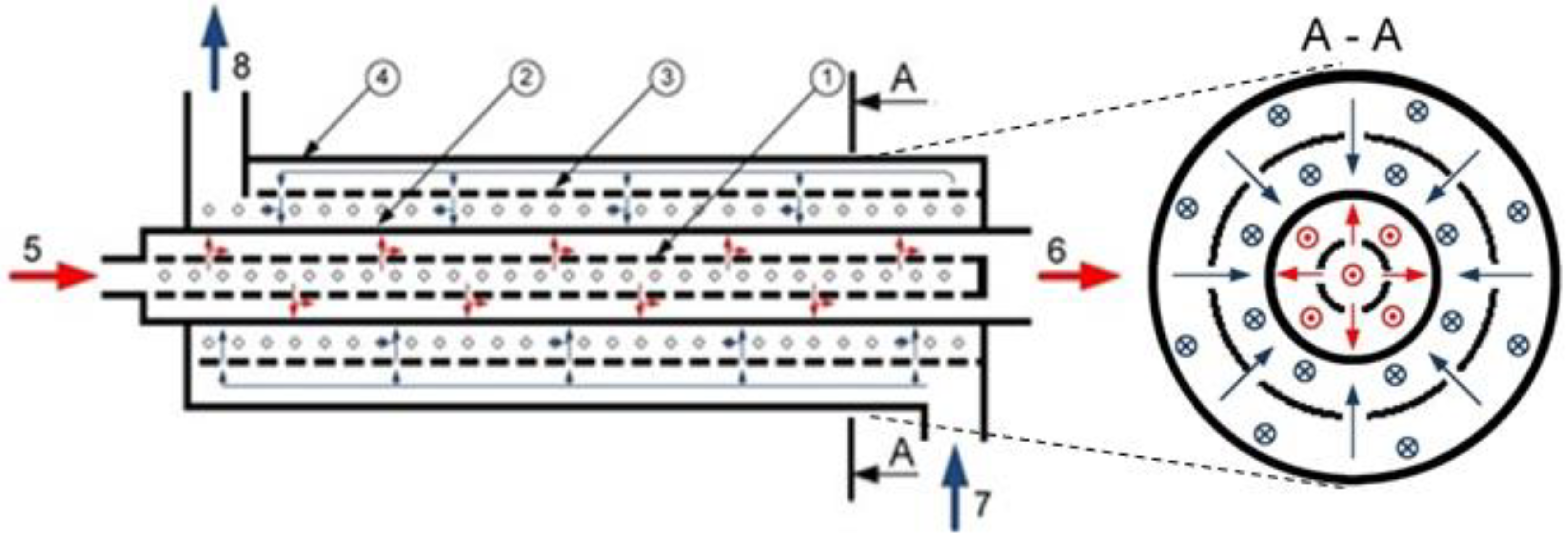
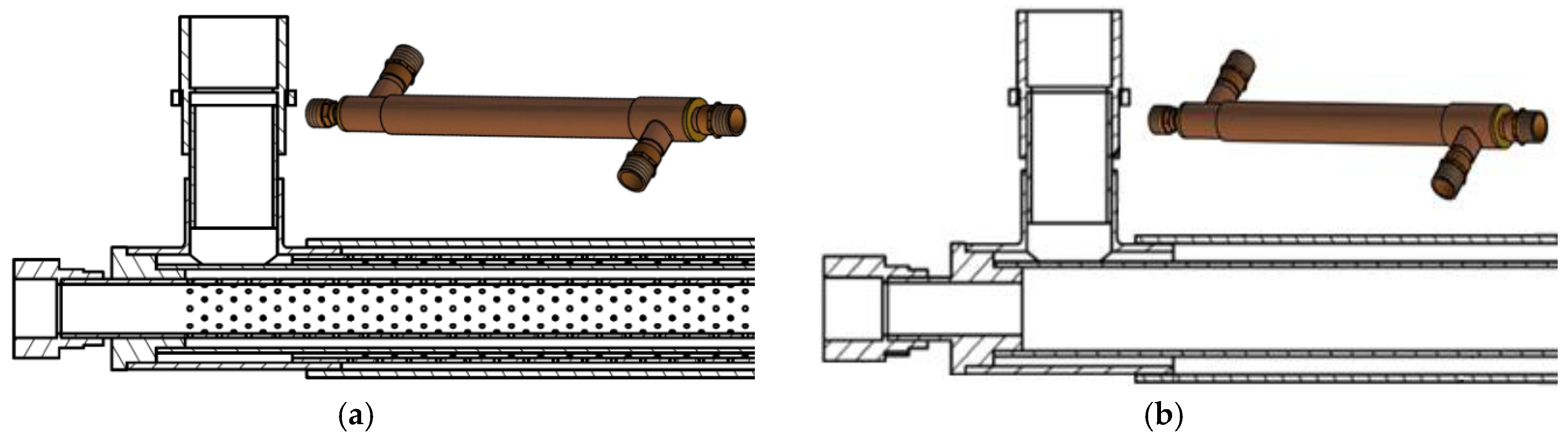
2.1. Minijets Heat Exchanger (MJHE)

The schematic diagram of the minijets heat exchanger with the heating and heated media perforated tubes as well as the heat transfer surface is shown in Figure 1. The notations present in the drawing are: 1,3—the perforated tube of the heating/heated medium; 2—the heat conducting wall; 4—the shell; 5,6—the inlet/outlet of the heating medium; 7,8—the inlet/outlet of the heated medium. The dashed line symbolize the perforated tubes, while the solid line represents the heat transfer (impinged) wall. From the heating medium, delivered by the inlet (5), the jets are formed in the perforated partition (1). They are radially directed toward the inner surface of the cylindrical heat transfer wall (2), imping on it and then as the cooled streams are flowing towards the outlet (6). The heated medium is delivered through the inlet (7) and it is flowing in the space between the shell (4) and perforated partition (3). This perforated partition creates the jets, which radially imping on the outer surface of the cylindrical heat transfer wall (2) and then as the heated ones are flowing towards the outlet (8).
Figure 2a presents the minijets heat exchanger cross-section and the view of its model (in the background of the drawing). The geometrical parameters of the heat exchanger are listed in Table 1.

2.2. Reference Heat Exchanger

For the needs of the comparative analysis, the classical shell-and-tube heat exchanger as a reference heat exchanger (RHE) was constructed without the jet impingement technology—the perforated tubes were removed from the structure. RHE was designed to match exactly the following dimensions of MJHE:
-
the heat exchange surface,
-
the diameters of the inlet and outlet connectors,
-
the diameters of the cylindrical heat transfer partition and the heat exchanger shell,
-
the length of the heat exchanger.
It should be emphasized that inside the heat exchangers different hydraulic diameters were obtained. In the case of MJHE, the space for the flowing fluid is additionally divided by a perforated partition. Two zones can be distinguished in it: the inflow zone to the perforate openings and the distributed flow zone after the jets’ impingement on the heat transfer surface. In the case of RHE, there is only one zone associated with the washing out of the heat transfer surface by the heating and heated fluids, respectively. The mentioned difference has an influence on the flow regime (laminar/turbulent), and consequently on the hydraulic resistance of the entire heat exchanger.

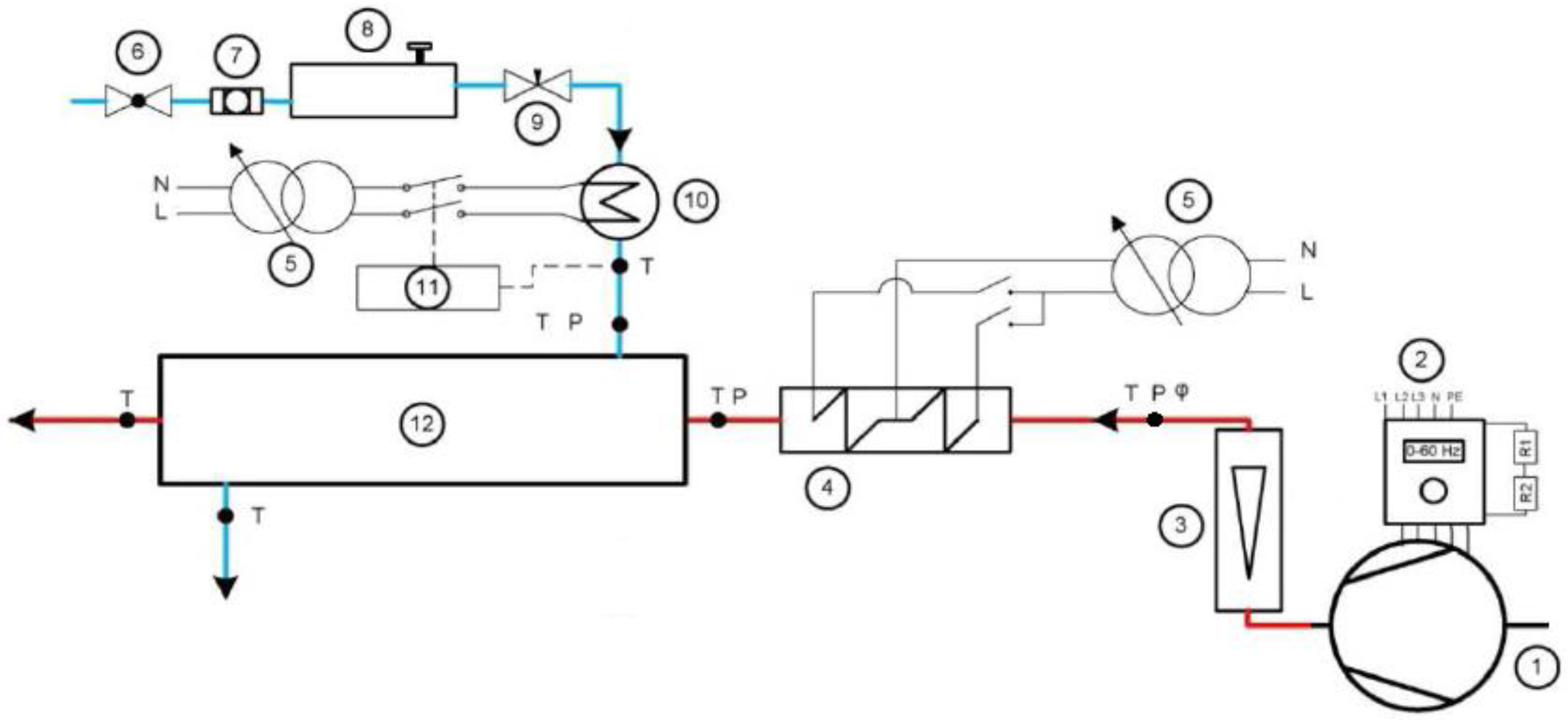
3. Experimental System

The experimental facility is schematically presented in Figure 3. It was designed for the purpose of the heat exchangers analyses and assembled at Gdansk University of Technology, Department of Energy and Industrial Apparatus. It can be adapted to the needs of various types of heat exchangers and all further described tests were carried out at this stand. In the presented analysis the facility was utilized to study convective heat transfer between the air as the heating medium and the water as the heated one.
The radial fan, controlled by the converter of frequency, forced the air flow through the experimental system. The air was flowing through the rotameter (the flow measurement section) then it was passing the heating section and finally entering the heat exchanger unit. The air heater consisted of two parts, which total capacity was 1.8 kW. It was controlled with high precision by the autotransformer. The water mass flow rate was regulated by the throttling valve and then measured by the mass flowmeter. The T-type thermocouples were used to measure the temperature at the heating and heated sides inlets and outlets of the heat exchanger unit. They were connected to the acquisition system and recorded signals were stored at the computer. The level of thermocouple accuracy (±0.1 K) was obtained due to an individual sensor calibration procedure done by the system of very high accuracy. Three temperature levels of heating air at the heat exchanger inlet were analyzed: 70, 100 and 130 °C, while the temperature of heated water was equal to 23 °C and kept constant in each measurement series. Such selection of temperature values was coming from a possible application of studied unit to heat recovery from low temperature gaseous waste heat sources. In Table 2, the measuring sensors and transducers, installed in the experimental stand are listed together with the technical data.

4. Results

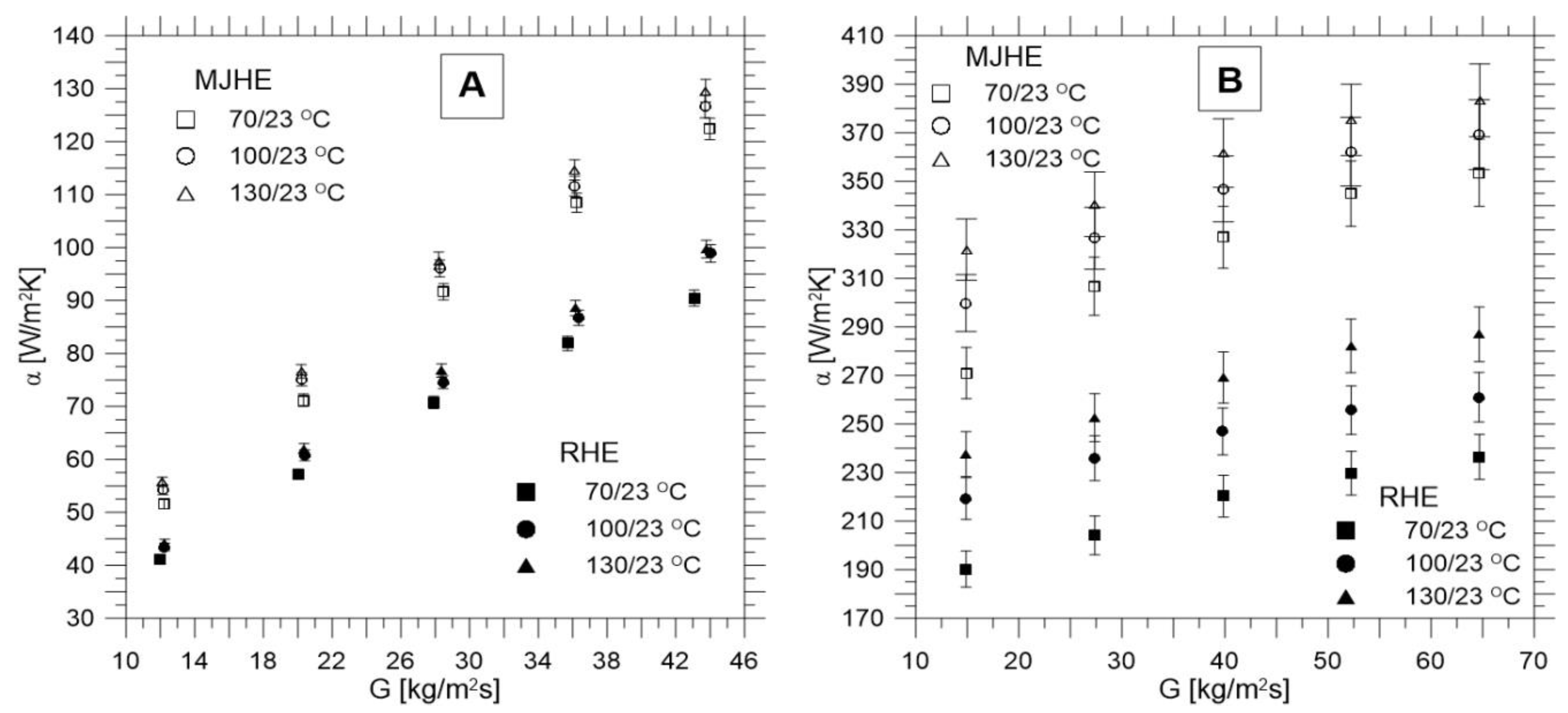
4.1. Thermal Characteristics

The tests of heat exchangers were carried out in countercurrent configuration with the recording of the thermal-hydraulic parameters: the temperature of the heating air at the heat exchanger inlet (thot, in) and the outlet (thot, out), temperature of the heated water at the heat exchanger inlet (tcold, in) and outlet (tcold, out), the air volume flow rate ( V ˙ ), the water mass flow rate ( m ˙ ) and the air pressure at the inlet to the heat exchanger (phot). In order to compare the characteristics of MJHE and RHE, tests of both heat exchangers were carried out for the identical volume flow rates of the working fluid and their inlets temperatures (in the equivalent measurement series). Volume flow rate of the air varied from 3 to 11 m3/h, while the mass flow rate of the water varied from 3 to 13 g/s.
During the mathematical modelling of the single-phase convection, the heat transfer coefficients were determined by the Wilson plot method [29]. This is the most suitable method for that purpose in the case of heat exchangers with complex geometry, because it is based only on the measurements of the volume flow rate and temperatures at the inlet and outlet connectors of the heat exchanger. It does not require temperature control at the heat transfer surface. The approach proposed by Wilson is based on the determination of the heat exchanger total thermal resistance and its division into the resistance of the individual heat transfer mechanisms in the recuperation process. This method allows estimation of an average values of the heat transfer coefficient for the heating and heated media by simple calculations.
A comparison of the analysed heat exchangers thermal characteristics is presented in Figure 4. They show a distribution of the heat transfer coefficient α, as a function of the mass flux G, (determined at the inlet of the tested heat exchangers) for the three temperature levels (previously mentioned values 70, 100 and 130 °C).
For both heat exchangers, the expected increase in the heat transfer coefficient is observed with an increase of the mass flux. Increasing air temperature causes an inconsiderable increase (about 5%) in the heat transfer coefficient for both heat exchangers. In the case of the heated side, this effect is more visible and falls within the range of 12–20%. Application of the jet impingement technology significantly intensified heat transfer in MJHE. An increase in the heat transfer coefficient for the heating side is about 25%. On the heated side, on the other hand, there is an increase of about 33% (a series of measurements with the greatest temperature difference between fluid 130/23 °C) and up to 45% (with a reduced temperature difference of 70/23 °C) was achieved.

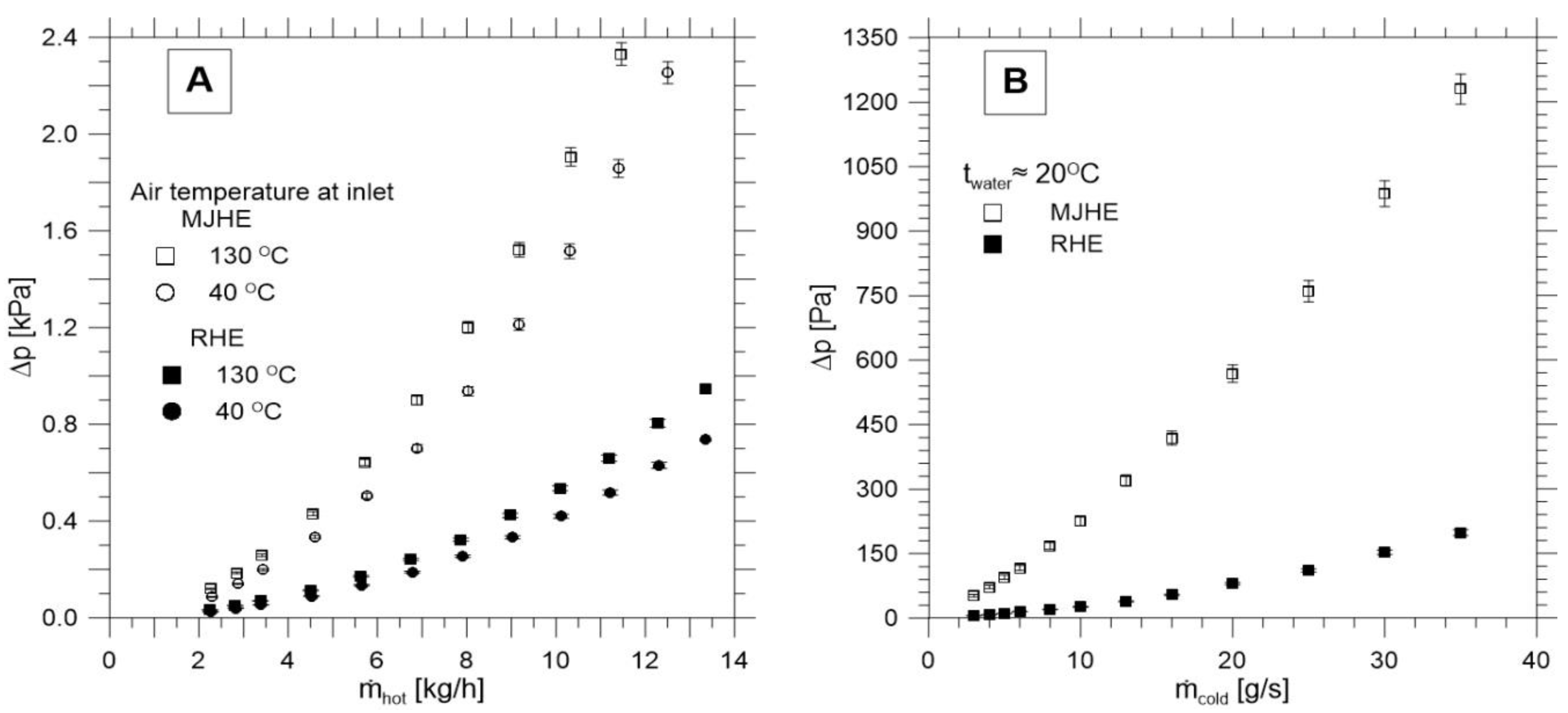
4.2. Hydraulic Characteristics

Experimental tests of hydraulic resistance for both heat exchangers were carried out at the temperature of the heated medium equal to 20 °C and at the two temperature levels of the heating medium, i.e., 40 and 130 °C. In these tests, the ranges of the analyzed flow rates were extended in relation to the ranges from the thermal tests (up to 13 m3/h for the air side and up to 35 g/s for the water side). In order to exclude an influence of the gravity component on the hydraulic resistance, the exchangers were placed in the horizontal position. The hydraulic characteristics are presented in Figure 5.
The hydraulic resistance on the heating side (air) increases with the increasing temperature. The tendency can be explained by an increase in the air viscosity and a decrease in its density—what with the given mass flow rate causes in consequence an increase in the air flow velocity inside the heat exchanger. The comparative analysis shows that an application of the jet technology is associated with an increase in the hydraulic resistance. For example, with the water mass flow rate of 13 g/s, the hydraulic resistance of MJHE is nearly 8 times higher than in the case of RHE, while for the air side the hydraulic resistance is only 4 times higher. However, when the low mass flow rate on the heating side (air), is considered (between 2 and 3 kg/h), the hydraulic resistance for both units is comparable. The reason can come from the uncertainties of mass flow measurement (Table 3), which should be taken into account. It should be also mentioned that a kind of imperfect assumptions were adopted during the design of RHE, which was designed to match the size of the heat transfer surface (making the thermal comparative studies easier) and the size of the heat exchanger shell. These assumptions cause a difference in the hydraulic diameters, which have a significant influence on the hydraulic resistance.

4.3. Analysis of the Measurements Uncertainies

An analysis of the measurement uncertainties is a very important point in all kinds of experimental studies. Regarding the presented investigations and taking into account a low number of measurement repetitions, the statistic uncertainties (type A and type B) in accordance with GUM [30] were not considered, because they are based on the probability distributions. It should be also pointed out, that the data were characterised by high repeatability. Therefore, the only analysis, which could be conducted, took into consideration the extended uncertainties analysis [30], which based on the uncertainties propagation principle, described by the formula [31]:
u ( y ) = k [ y x k u ( x k ) ] 2 .
The relative uncertainty of the determined quantity was calculated in accordance with Equation (2):
δ y = u ( y ) y 100 % .
The list of the maximum values of this uncertainty, specified for the thermal and flow parameters discussed in the work, is presented in Table 3.

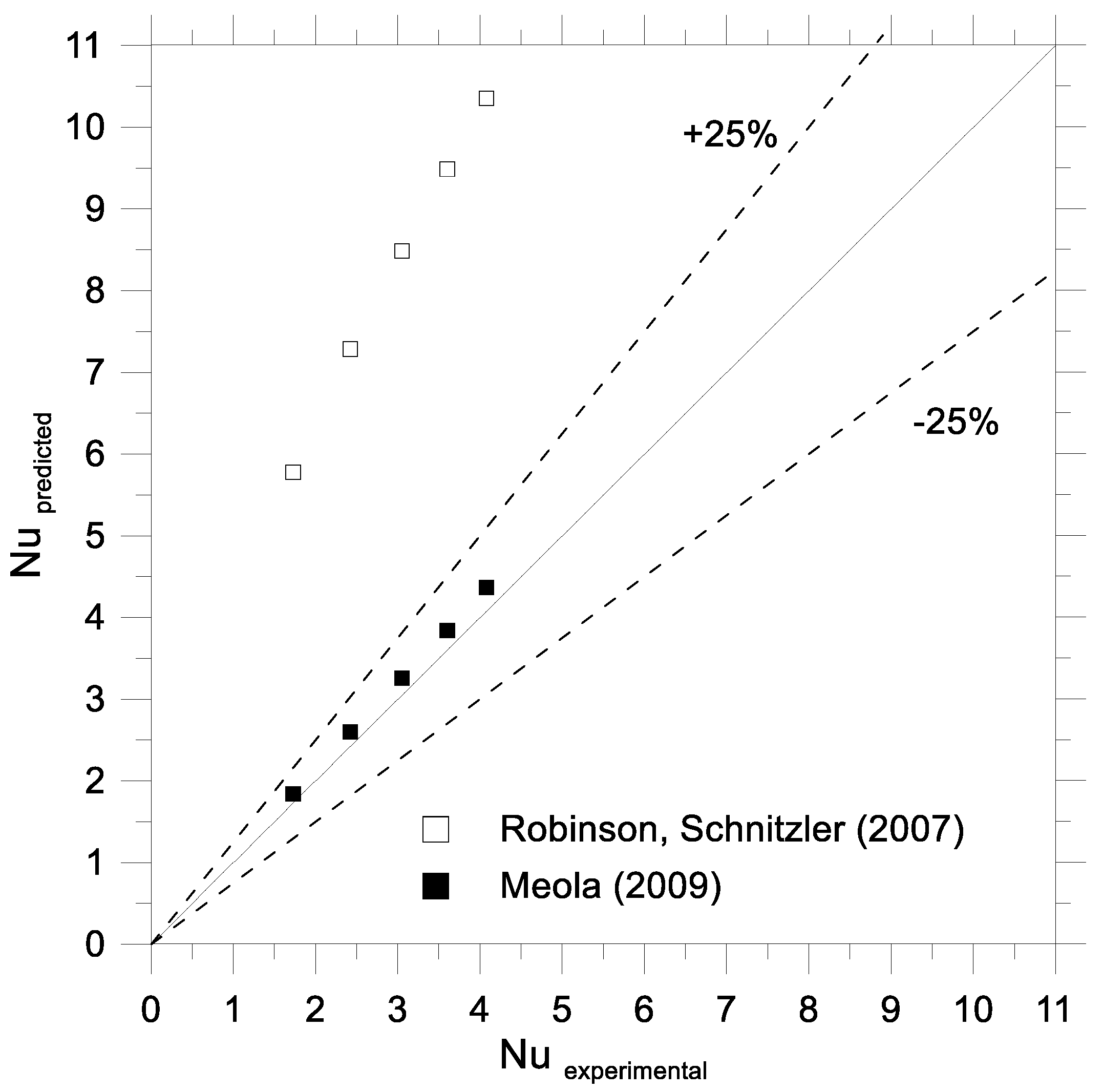
5. Validation of the Exemplary Nusselt Number Correlations

The Nusselt number values based on the results of the experimental studies were related to the results of the mathematical modeling using two correlations presented in the literature. For this purpose, the correlations developed for the submerged jets were selected, which corresponded with the authors’ own research case. The comparative analysis was based on Robinson and Schnitzler [32] and Meola [33] the correlations, presented in Table 4. The symbols used in the table represent respectively: d—the orifice diameter, H—the distance between orifice and the heat exchange surface, Cf—the flow coefficient, S—the distance between the adjacent holes, Re—the Reynolds number, Pr—the Prandtl number.
The Nusselt number for the experimental studies was calculated on the basis of the average heat transfer coefficient (α) and the diameter of the orifice forming a single jet (d), using the following relationship:
Nu exp = α d λ .
It should be emphasized that in the described experiment, the values of the Reynolds number (defined on the basis of the orifice diameter) are definitely lower than the values for which the mentioned correlations from the literature were developed. In particular, this applies to the water side, for which in the case of Robinson and Schnitzler [32] the discrepancy is even 100 times, and in the case of Meola [33] about 30 times. In connection with the above, the comparative analysis was performed only for the heating (air) side, and the results of these calculations are plotted in Figure 6. They indicate very good agreement of the experimental values of the Nusselt number with the values determined by the Meola correlation (constructed also for the air jets), while they exhibit a lack of correspondence with the values obtained by the Robinson and Schnitzler correlation. Further experimental analyses considering higher flow rates values of heating and heated media are planned. Special attention will be placed on the analysis of the water side for the purpose of its comparison with the Meola correlation.

6. Future Works

Before going to the conclusions coming from the presented results, the issue of hydraulic diameter is called once again. As it was mentioned in Section 2.2, the difference in the hydraulic diameter of MJHE and RHE, has an influence on the flow regime (laminar/turbulent), and consequently on the hydraulic resistance of the entire heat exchanger and then the heat transfer coefficient. Since the present research concentrated on keeping the same overall unit size and the thermo-flow conditions this aspect was not analyzed. However, the authors are aware of significance of this difference. Therefore the experimental analyses are still going on the determination of both hydraulic diameters, their difference and a minimization of its effect with the mass flow rate or the pressure. Moreover, to evaluate an importance of the measurement uncertainties on the hydraulic resistance in the range of low mass flow rate values, an additional studies will be conducted at even lower values.

7. Conclusions

The paper briefly discusses the heat exchanger of cylindrical construction, which uses the jet technology for the purpose of heat transfer intensification. To assess the extent of this intensification, a tubular reference heat exchanger was constructed. Both heat exchangers were tested in the single-phase convection with the participation of hot air as a heating medium and water as a heated medium. Based on the collected data, it can be concluded that the application of jet technology in the heat exchanger is very beneficial in the heat transfer aspect. An increase in the heat transfer coefficients values by about 45% at the lowest temperature difference between heating and the heated medium was observed. As expected, the generated minijets caused greater hydraulic resistance, what is typical for the passive methods of heat transfer enhancement. These conclusions, coming from the present results, will be validated during the studies on the minimization of the hydraulic diameter difference effect, in the near future. Experimentally confirmed intensification of heat transfer on the air side makes the proposed minijets heat exchanger application more attractive, for the waste heat utilization systems from gas sources (especially low-temperature carriers). In addition, the compactness of the design makes this heat exchanger an ideal proposal for micro-CHP (for example as the regenerator for high-efficiency air turbine cycles [34,35]).

Author Contributions

Conceptualization, J.W.; Methodology, J.W.; Validation, J.W. and M.B.; Formal Analysis, J.W., M.B. and D.M.; Investigation, M.B.; Resources, J.W. and D.M.; Data Curation, M.B. and J.W.; Writing—Original Draft Preparation, J.W.; Writing—Review & Editing, J.W.; Visualization, M.B.; Supervision, J.W. and D.M.; Project Administration, J.W.; Funding Acquisition, D.M. and M.B.

Funding

This research received no external funding.

Conflicts of Interest

The authors declare no conflict of interest.

Nomenclature

Aheat transfer area, m2
Antotal nozzle area, m2
cpspecific heat, J/(kg·K)
Cfflow coefficient,
dorifice diameter, m
frelative nozzle area, f = ( n 0.25 π d 2 ) / A
Gmass flux, kg/(m2·s)
Hdistance between nozzle and impingement surface, m
m ˙ mass flow rates, kg/h, g/s
nnumber of orifices forming the jets,
NuNusselt number, N u = ( α d ) / λ
ppressure, Pa
PrPrandtl number, Pr = ( μ c p ) / λ
Sjet-to-jet spacing, m
ReReynolds number, Re = ( m ˙ d ) / ( A n μ )
ttemperature, °C
V ˙ volume flow rates, m3/h
u(y)uncertainty of determined quantity
u(xk)maximal uncertainty of measured/calculated component
Greek letters
αheat transfer coefficient, W/(m2·K)
Δdifference value,
δyrelative uncertainty of determined quantity, %
λthermal conductivity of fluid, W/(m·K)
μdynamic viscosity of fluid, Pa·s
Subscripts
coldin regard to heated medium
expexperiment
hotin regard to heating medium
ininlet
outoutlet

References

  1. Kreith, F.; Goswami, D.Y. The CRC Handbook of Mechanical Engineering, 2nd ed.; CRC Press LLC: Boca Raton, FL, USA, 2005. [Google Scholar]
  2. Rohsenow, W.M.; Hartnett, J.P.; Cho, Y.I. Handbook of Heat Transfer; McGraw-Hill: New York, NY, USA, 1998. [Google Scholar]
  3. Bergles, A.E. The implications and challenges of enhanced heat transfer for the chemical process industries. Chem. Eng. Res. Des. 2001, 79, 437–444. [Google Scholar] [CrossRef]
  4. Błasiak, P.; Pietrowicz, S. Towards a better understanding of 2D thermal-flow processes in a scraped surface heat exchanger. Int. J. Heat Mass Transf. 2016, 98, 240–256. [Google Scholar] [CrossRef]
  5. Gondrexon, N.; Rousselet, Y.; Legay, M.; Boldo, P.; Le Person, S.; Bontemps, A. Intensification of heat transfer process: Improvement of shell-and-tube heat exchanger performances by means of ultrasound. Chem. Eng. Process. 2010, 49, 936–942. [Google Scholar] [CrossRef]
  6. Legay, M.; Simony, B.; Boldo, P.; Gondrexon, N.; Le Person, S.; Bontemps, A. Improvement of heat transfer by means of ultrasound: Application to a double-tube heat exchanger. Ultrason. Sonochem. 2012, 19, 1194–1200. [Google Scholar] [CrossRef] [PubMed]
  7. Wajs, J.; Mikielewicz, D. Effect of surface roughness on thermal-hydraulic characteristics of plate heat exchanger. Key Eng. Mater. 2014, 597, 63–74. [Google Scholar] [CrossRef]
  8. Kalawa, W.; Wójcik, T.M.; Piasecka, M. Heat transfer research on enhanced heating surfaces in pool boiling. EPJ Web Conf. 2017, 143, 02048. [Google Scholar] [CrossRef]
  9. Jafari, R.; Okutucu-Özyurt, T.; Ünver, H.Ö.; Bayer, Ö. Experimental investigation of surface roughness effects on the flow boiling of R134a in microchannels. Exp. Therm. Fluid Sci. 2016, 79, 222–230. [Google Scholar] [CrossRef]
  10. Strąk, K.; Piasecka, M.; Maciejewska, B. Spatial orientation as a factor in flow boiling heat transfer of cooling liquids in enhanced surface minichannels. Int. J. Heat Mass Transf. 2018, 117, 375–387. [Google Scholar] [CrossRef]
  11. Akpinar, E.K.; Bicer, Y.; Yildiz, C.; Pehli̧van, D. Heat transfer enhancements in a concentric double pipe exchanger equipped with swirl elements. Int. Commun. Heat Mass 2004, 31, 857–868. [Google Scholar] [CrossRef]
  12. Akpinar, E.K. Evaluation of heat transfer and exergy loss in a concentric double pipe exchanger equipped with helical wires. Energy Convers. Manag. 2006, 47, 3473–3486. [Google Scholar] [CrossRef]
  13. Cieśliński, J.T.; Fiuk, A.; Miciak, W.; Siemieńczuk, B. Performance of a plate heat exchanger operated with water-Al2O3 nanofluid. Appl. Mech. Mater. 2016, 831, 188–197. [Google Scholar] [CrossRef]
  14. Huang, D.; Wu, Z.; Sunden, B. Effects of hybrid nanofluid mixture in plate heat exchangers. Exp. Therm. Fluid Sci. 2016, 72, 190–196. [Google Scholar] [CrossRef]
  15. Wajs, J.; Mikielewicz, D.; Jakubowska, B. Performance of the domestic micro ORC equipped with the shell-and-tube condenser with minichannels. Energy 2018, 157, 853–861. [Google Scholar] [CrossRef]
  16. Ma, T.; Li, L.; Xu, X.-Y.; Chen, Y.-T.; Wang, Q.-W. Study on local thermal–hydraulic performance and optimization of zigzag-type printed circuit heat exchanger at high temperature. Energy Convers. Manag. 2015, 104, 55–66. [Google Scholar] [CrossRef]
  17. Aneesh, A.M.; Sharma, A.; Srivastava, A.; Vyas, K.N.; Chaudhuri, P. Thermal-hydraulic characteristics and performance of 3D straight channel based printed circuit heat exchanger. Appl. Therm. Eng. 2016, 98, 474–482. [Google Scholar] [CrossRef]
  18. Dąbrowski, P.; Klugmann, M.; Mikielewicz, D. Channel blockage and flow maldistribution during unsteady flow in a model microchannel plate heat exchanger. J. Appl. Fluid Mech. 2019, 12, 1023–1035. [Google Scholar] [CrossRef]
  19. Klugmann, M.; Dabrowski, P.; Mikielewicz, D. Pressure drop related to flow maldistribution in a model minichannel plate heat exchanger. Arch. Thermodyn. 2018, 39, 123–146. [Google Scholar]
  20. Kumar, R.; Singh, G.; Mikielewicz, D. New approach for the mitigating of flow maldistribution in parallel microchannel heat sink. J. Heat Transf. 2018. [Google Scholar] [CrossRef]
  21. Chauhan, R.; Singh, T.; Thakur, N.S.; Kumar, N.; Kumar, R.; Kumar, A. Heat transfer augmentation in solar thermal collectors using impinging air jets: A comprehensive review. Renew. Sustain. Energy Rev. 2018, 82, 3179–3190. [Google Scholar] [CrossRef]
  22. Zukowski, M. Heat transfer performance of a confined single slot jet of air impinging on a flat surface. Int. J. Heat Mass Transf. 2013, 57, 484–490. [Google Scholar] [CrossRef]
  23. Zukowski, M. Experimental investigations of thermal and flow characteristics of a novel microjet air solar heater. Appl. Energy 2015, 142, 10–20. [Google Scholar] [CrossRef]
  24. Wajs, J.; Mikielewicz, D.; Fornalik-Wajs, E. Microjet Heat Exchanger with a Cylindrical Geometry, Especially for Heat Recovery from Low-Temperature Waste Energy Sources. Polish Patent PL224494, 8 July 2013. (In Polish). [Google Scholar]
  25. Kura, T.; Fornalik-Wajs, E.; Wajs, J. Thermal and hydraulic phenomena in boundary layer of minijets. Arch. Thermodyn. 2018, 39, 147–166. [Google Scholar]
  26. Nakabe, K.; Fornalik, E.; Eschenbacher, J.F.; Yamamoto, Y.; Ohta, T.; Suzuki, K. Interactions of longitudinal vortices generated by twin inclined jets and enhancement of impingement heat transfer. Int. J. Heat Fluid Flow 2001, 22, 287–292. [Google Scholar] [CrossRef]
  27. Wajs, J.; Mikielewicz, D.; Fornalik-Wajs, E.; Bajor, M. Recuperator with microjet technology as a proposal for heat recovery from low-temperature sources. Arch. Thermodyn. 2015, 36, 48–63. [Google Scholar] [CrossRef]
  28. Wajs, J.; Mikielewicz, D.; Fornalik-Wajs, E.; Bajor, M. High performance tubular heat exchanger with minijet heat transfer enhancement. Heat Transf. Eng. 2019, 40, 772–783. [Google Scholar] [CrossRef]
  29. Shah, R.K. Assessment of Modified Wilson Plot Techniques for Obtaining Heat Exchanger Design Data. In Proceedings of the 9th International Heat Transfer Conference, Jerusalem, Israel, 19–24 August 1990. [Google Scholar]
  30. Working Group 1 of the Joint Committee for Guides in Metrology. Evaluation of Measurement Data–Guide to the Expression of Uncertainty in Measurement; JCGM, 2008; Available online: https://www.bipm.org/utils/common/documents/jcgm/JCGM_100_2008_E.pdf (accessed on 9 August 2019).
  31. Zieba, A. Analysis of the Data in Science and Technology; PWN: Warszawa, Poland, 2013. (In Polish) [Google Scholar]
  32. Robinson, A.J.; Schnitzler, E. An experimental investigation of free and submerged miniature liquid jet array impingement heat transfer. Exp. Therm. Fluid Sci. 2007, 32, 1–13. [Google Scholar] [CrossRef]
  33. Meola, C. A new correlation of Nusselt number for impinging jets. Heat Transf. Eng. 2009, 30, 221–228. [Google Scholar] [CrossRef]
  34. Kosowski, K.; Tucki, K.; Piwowarski, M.; Stępień, R.; Orynycz, O.; Włodarski, W.; Bączyk, A. Thermodynamic cycle concepts for high-efficiency power plans. Part A: Public power plants 60+. Sustainability 2019, 11, 554. [Google Scholar] [CrossRef]
  35. Kosowski, K.; Tucki, K.; Piwowarski, M.; Stępień, R.; Orynycz, O.; Włodarski, W. Thermodynamic cycle concepts for high-efficiency power plants. Part B: Prosumer and distributed power industry. Sustainability 2019, 11, 2647. [Google Scholar] [CrossRef]
Figure 1. The minijet heat exchanger (MJHE)—schematic diagram.
Energies 12 03276 g001
Figure 2. (a) Cross-section of the minijet heat exchanger and its model. (b) Cross-section of the classical shell-and-tube heat exchanger and its model.
Energies 12 03276 g002
Figure 3. Diagram of the system; 1—radial fan, 2—inverter, 3—rotameter, 4—air heater, 5—autotransformer, 6—main water valve, 7—filter, 8—mass flowmeter, 9—throttling valve, 10—water heater, 11—relay regulator, 12—heat exchanger.
Energies 12 03276 g003
Figure 4. Heat transfer coefficients versus the mass flow density: (A)—heating side (air), (B)—heated side (water).
Energies 12 03276 g004
Figure 5. Flow characteristics of MJHE and RHE for: (A)—heating side (air), (B)—heated side (water).
Energies 12 03276 g005
Figure 6. The Nusselt number predictions versus the authors’ own experimental data (heating side).
Energies 12 03276 g006
Table 1. Geometrical parameters of the MJHE.
ParameterSize
Length of the heat transfer wall (m)0.281
Outer diameter of the heat transfer wall (m)0.018
Thickness of the heat transfer wall, t (m)0.001
Heat transfer area, A (m2)0.015
Inner diameter of the connection—heating side (m)0.012
Inner diameter of the connection—heated side (m)0.015
Orifice diameter, d (m)0.001
Number of orifices (heating/heated side), n752/820
Distance between the orifice
and the heat transfer wall—heating side, h (m)
0.002
Distance between the orifice
and the heat transfer wall—heated side, h (m)
0.001
Nozzle-to-nozzle spacing, S (m)0.004
Table 2. List of the measuring sensors and transducers installed in the experimental stand.
NameMeasured ParameterProducer, Type/ModelMeasurement RangeMaximal Mesurement Uncertainty
Rotameterair volume flow rateMetalchem, ROL-2531.2 ÷ 18.8 m3/h±2.5% ZP
Pressure transducerair pressure:
(1) behind the rotameter
(2) at the inlet to hx
Peltron, NPXA 20 ÷ 200 kPa abs.±0.1% ZP
(±0.2 kPa)
T type thermocoupletemperatureCzach, TTP-1-100–0,5–100 ÷ 400 °C±0.5 °C
Mass flowmeter with the signal converterwater mass flow rateSiemens /Massflo, MASS 2100, DI 30 ÷ 250 kg/h
(0 ÷ 69.4 g/s)
±0.15% of instantaneous flow rate
Pressure transducerwater pressure at the inlet to hx Peltron, NPXA 20 ÷ 200 kPa abs.±0.25% ZP
(±0.5 kPa)
Askania micromanometerhydraulic resistance on the air (heating medium) side Zakłady “Szopienice”, MK-20 ÷ 250 mm H2O±0.13 mm H2O
Electronic micromanometerhydraulic resistance on the water (heated medium) sideFurness Controls, FCO12ZI: ±19 mm H2O
ZII: ±99 mm H2O
±0.5% ZP
(ZI: ±0.1 mm H2O; ZII: ±1.0 mm H2O)
Table 3. Maximal uncertainties values.
QuantityRelative Value [%]
Air volumetric flow rate8.78
Water mass flow rate1.16
Temperature0.76
Pressure drop1.10
Heat rate13.14
Heat transfer coefficients (heating side)1.66
Heat transfer coefficients (heated side)6.91
Mass flux (heating side)9.68
Mass flux (heated side)1.15
Table 4. The Nusselt number correlations selected for the comparison.
Author(s)Nusselt Number CorrelationComment
Robinson and Schnitzler [32] Nu L = 23.39 Pr 0.4 Re d 0.46 ( S d ) 0.442 ( H d ) 0.00716
Nu = 0.0635 Nu L
2 H d 3 ; 3 S d 7 ; 650 Re 6500
Meola [33] Nu = 0.3 Pr 0.42 Re 0.68 C f 0.56 ( H d ) 0.3 f 0.15 1.6 H d 20 ; 0.0008 f 0.2 ; 200 Re 10,000

