Optimal Stator Design of Doubly Salient Permanent Magnet Generator for Enhancing the Electromagnetic Performance


Abstract
:
1. Introduction
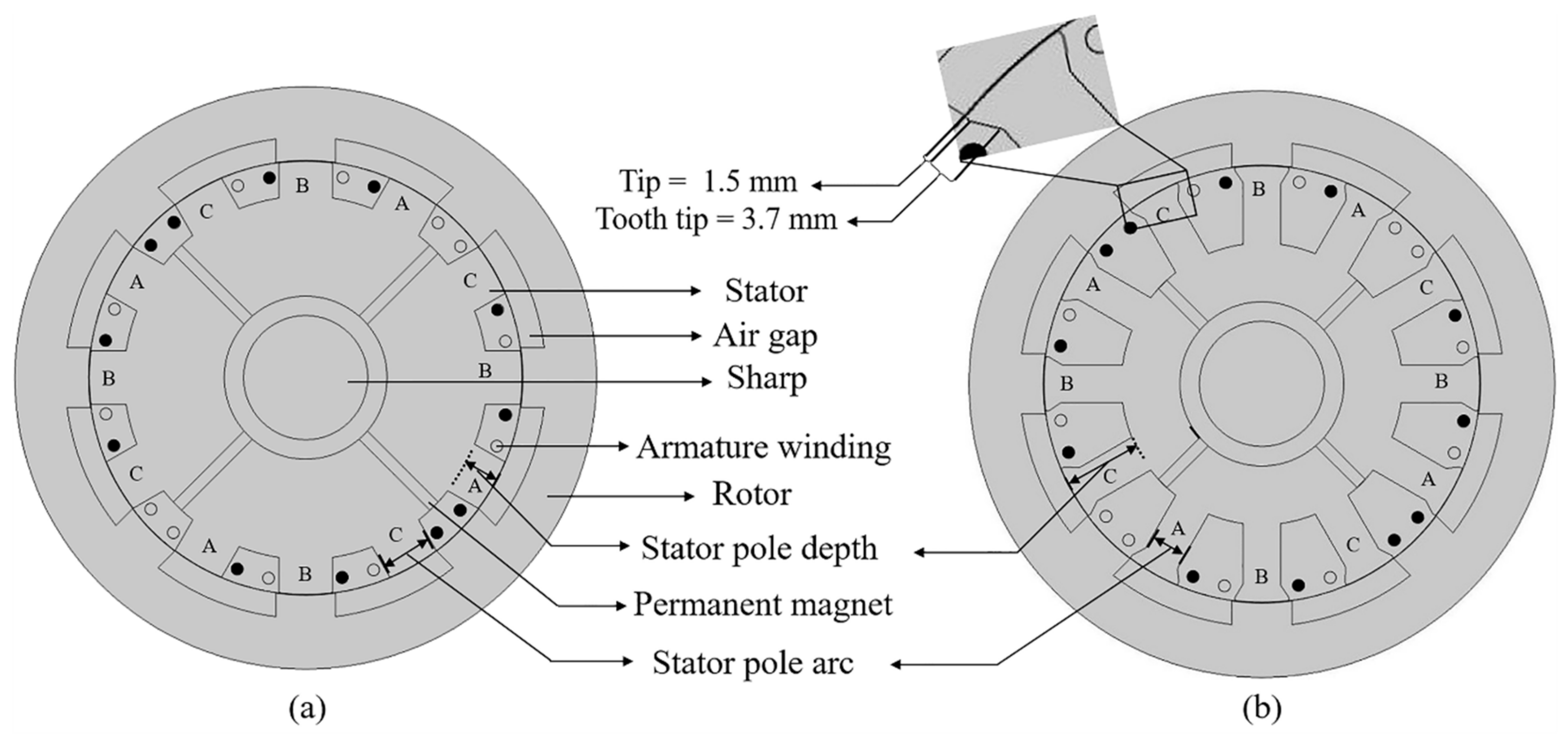
2. Machine Design
2.1. Magnetic Field Distribution Analysis
2.2. Analysis of Machine Characteristics
3. Results and Discussion
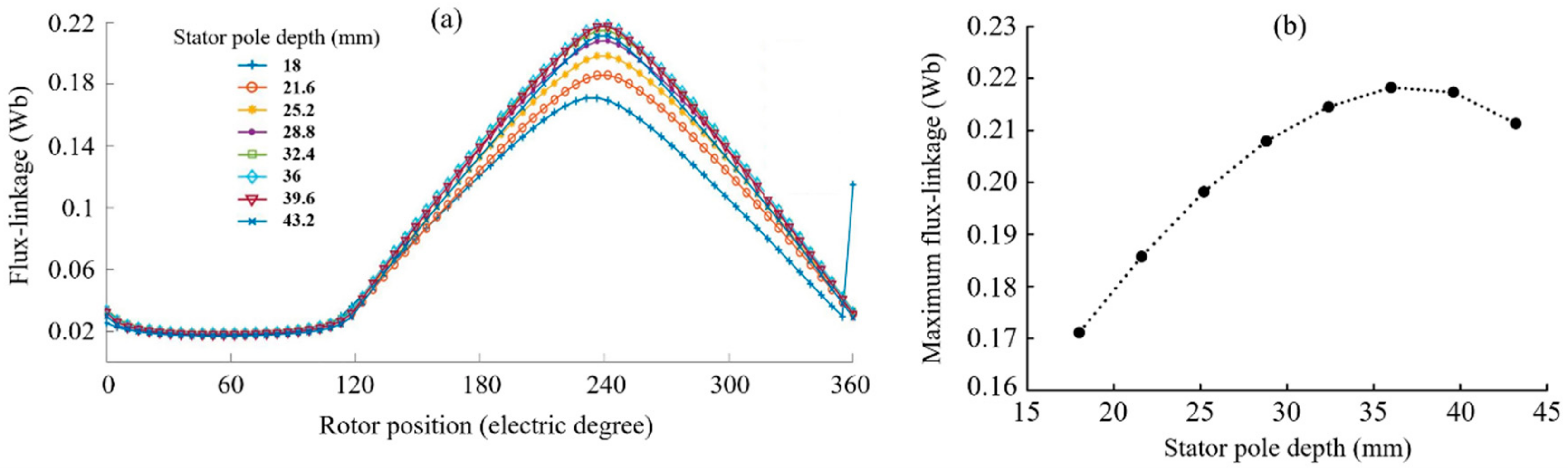
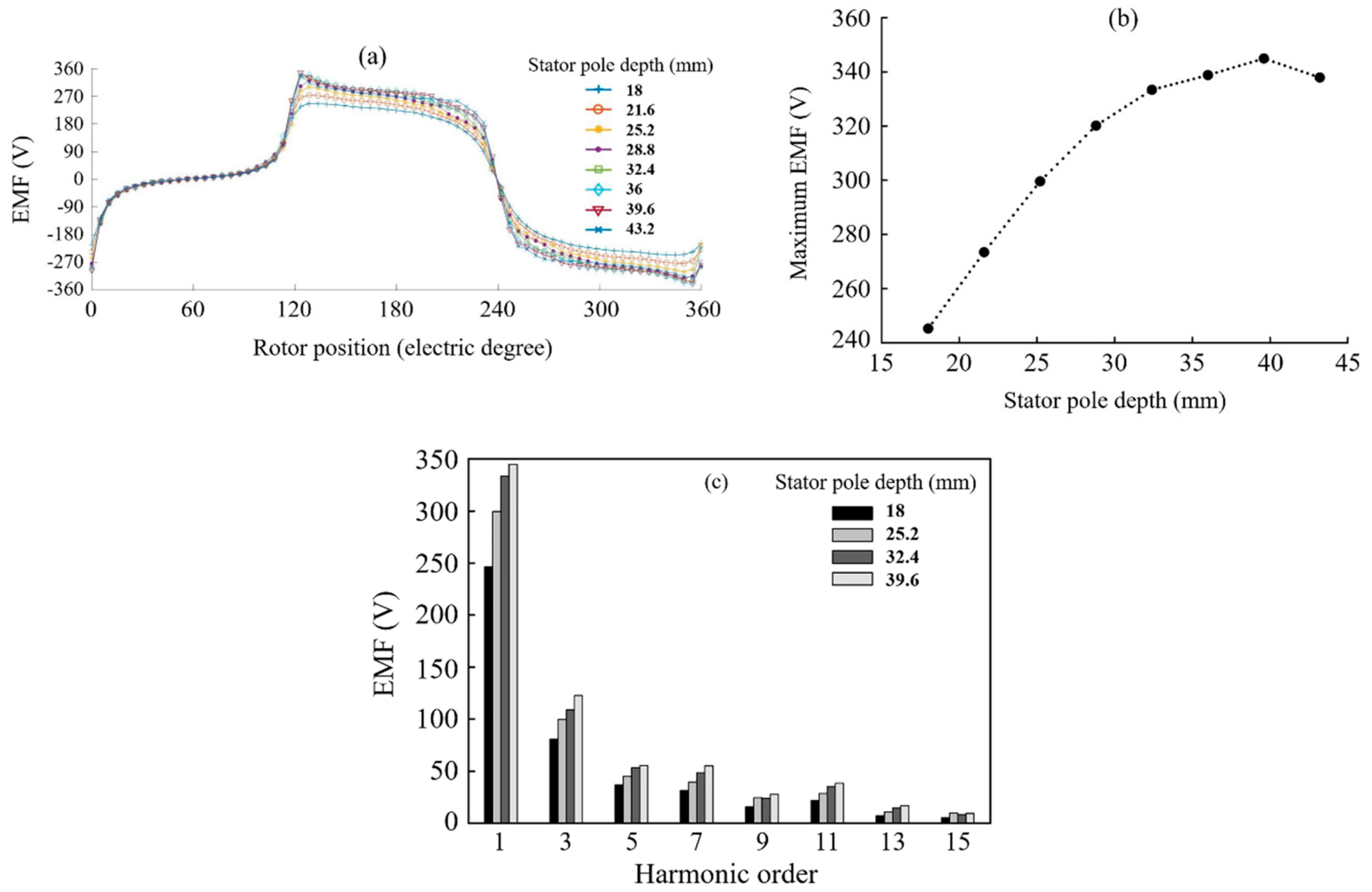
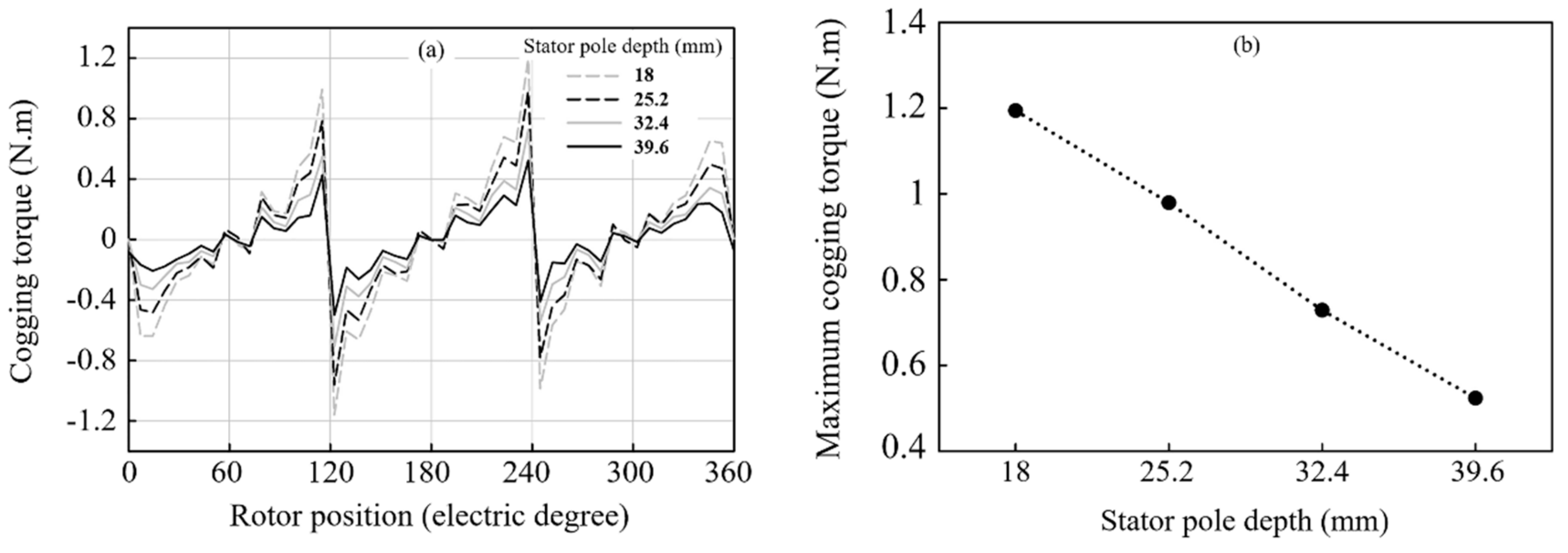
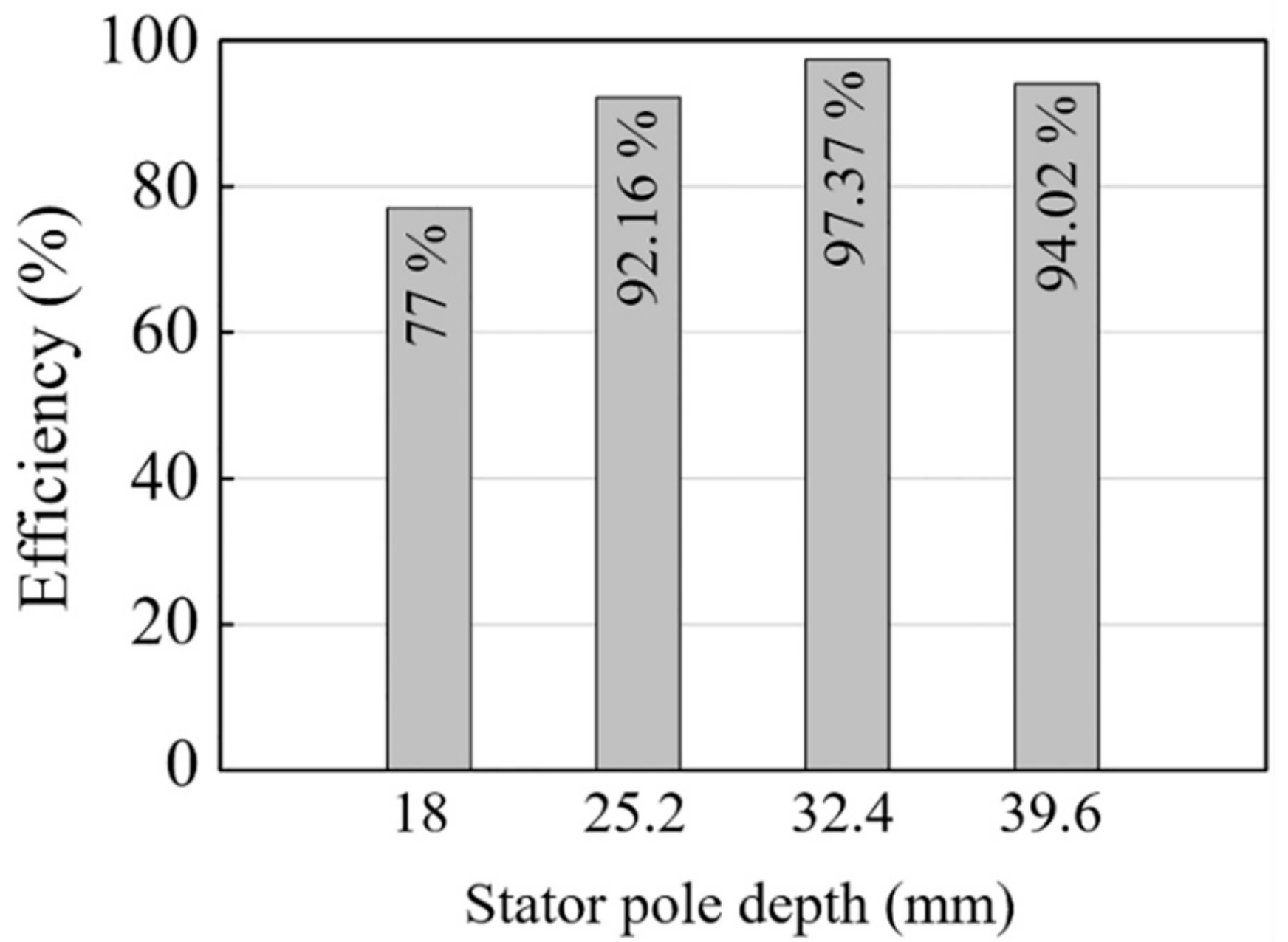
3.1. Influence of Stator Pole Depth on the Generator Outputs
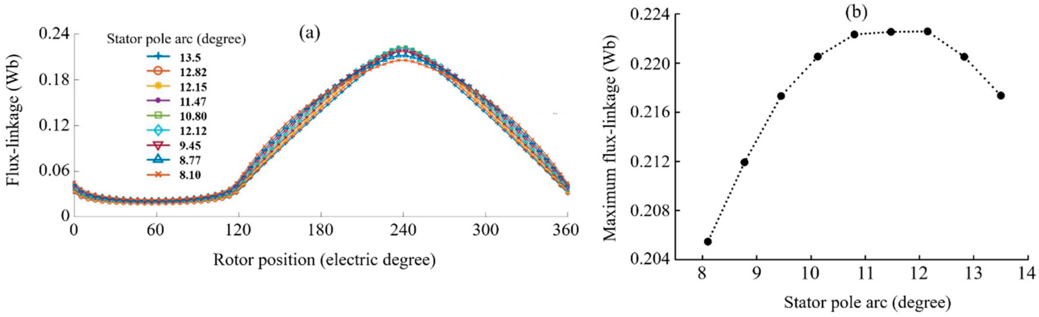
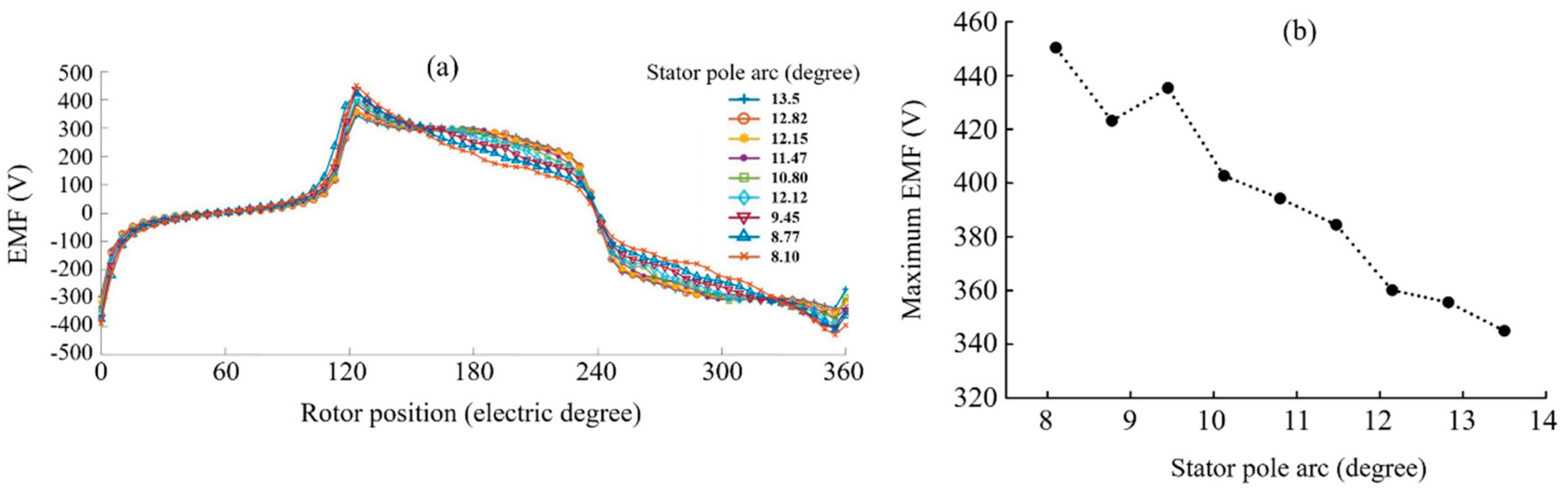
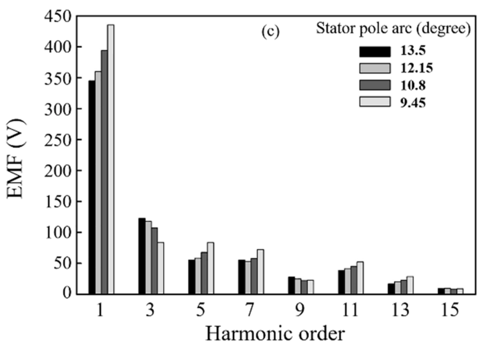
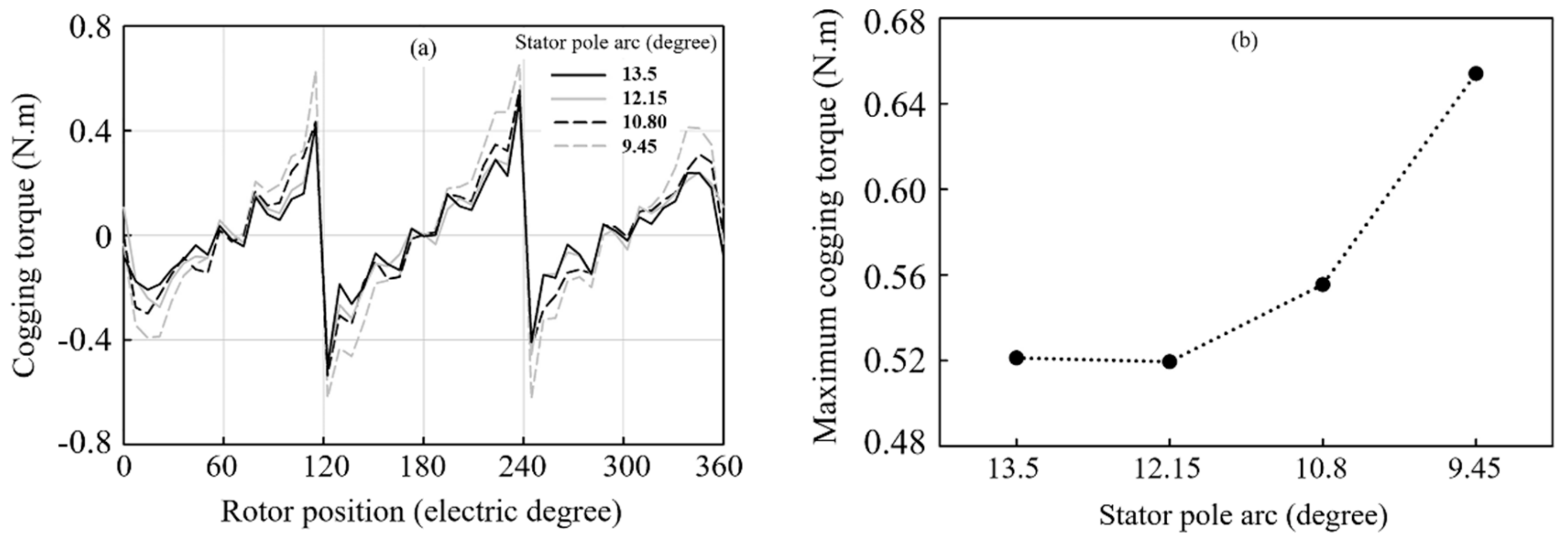
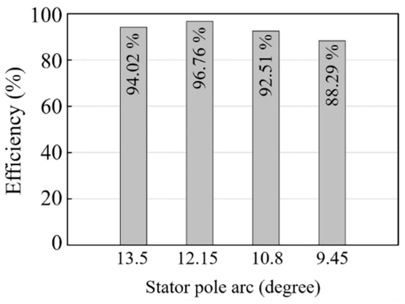
3.2. Influence of Stator Pole Arc on the Generator Outputs
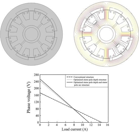
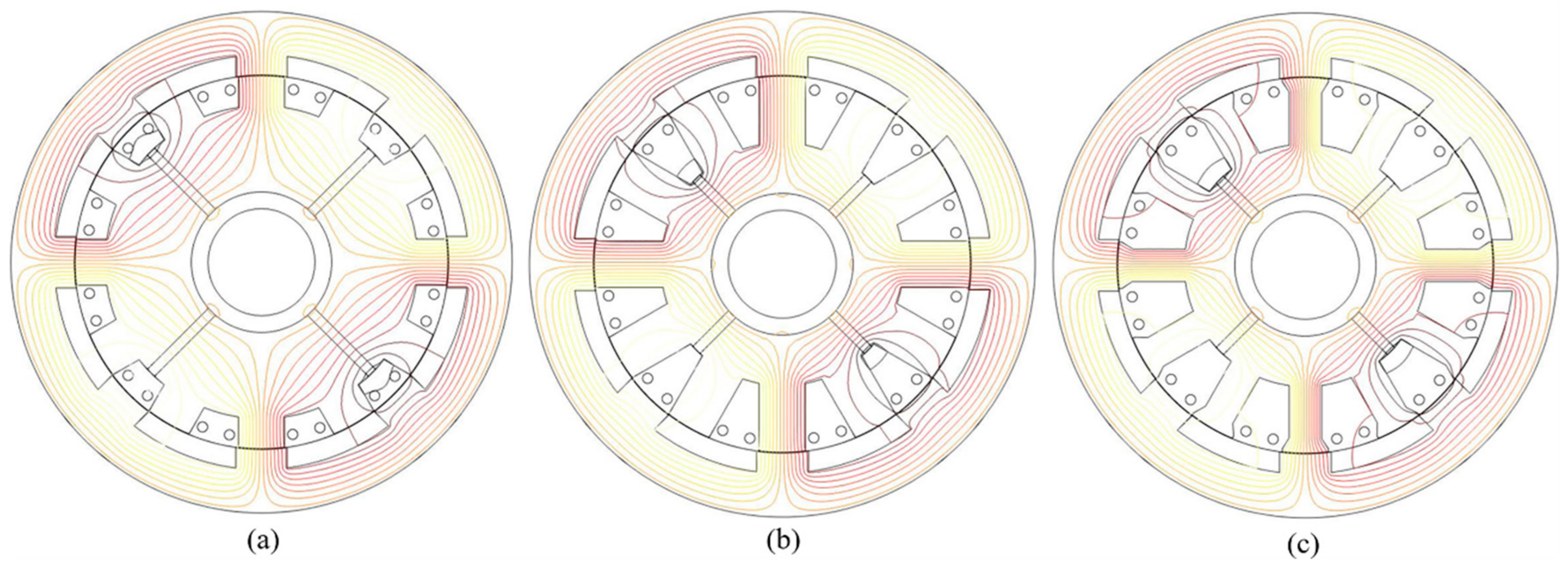
3.3. Magnetic Flux Distribution Analysis
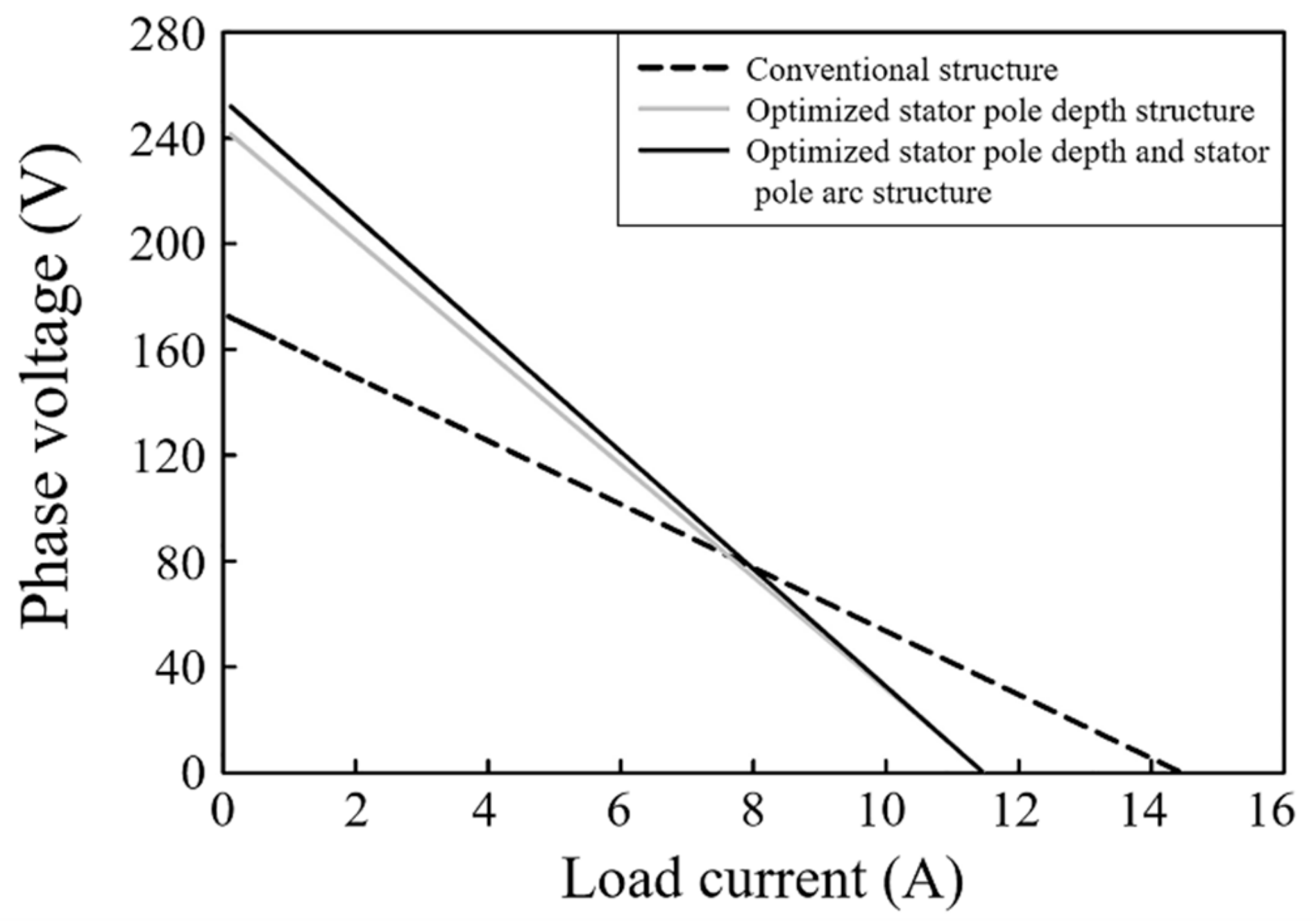
3.4. Voltage Regulation Analysis
4. Conclusions
Author Contributions
Funding
Acknowledgments
Conflicts of Interest
References
- Wang, Y.; Niu, S.; Fu, W. Electromagnetic Performance Analysis of Novel Flux-Regulatable Permanent Magnet Machines for Wide Constant-Power Speed Range Operation. Energies 2015, 8, 13971–13984. [Google Scholar] [CrossRef] [Green Version]
- Chau, K.T.; Chan, C.C.; Liu, C. Overview of permanent-magnet brushless drives for electric and hybrid electric vehicles. IEEE Trans. Ind. Electron. 2008, 6, 2246–2257. [Google Scholar] [CrossRef]
- Cheng, M.; Hua, W.; Zhang, J.; Zhao, W. Overview of stator-permanent magnet brushless machines. IEEE Trans. Ind. Electron. 2011, 58, 5087–5101. [Google Scholar] [CrossRef]
- Ko, H.S.; Kim, K.J. Characterization of noise and vibration sources in interior permanent-magnet brushless DC motors. IEEE Trans. Magn. 2004, 6, 3482–3489. [Google Scholar] [CrossRef]
- Gieras, J.F.; Wang, R.J.; Kamper, M.J. Axial Flux Permanent Magnet Brushless Machines, 2nd ed.; Springer-Verlag: New York, NY, USA, 2008. [Google Scholar]
- Shao, L.; Hua, W.; Dai, N.; Tong, M.; Cheng, M. Mathematical modeling of a twelve-phase flux-switching permanent-magnet machine for wind power generation. IEEE Trans. Ind. Electron. 2016, 63, 504–516. [Google Scholar] [CrossRef]
- Gao, Y.; Qu, R.; Li, D.; Li, J.; Zhou, G. Consequent-pole flux-reversal permanent-magnet machine for electric vehicle propulsion. IEEE Trans. Appl. Supercond. 2016, 26, 5200105. [Google Scholar] [CrossRef]
- Zhao, J.; Yan, Y.; Li, B.; Liu, X.; Chen, Z. Influence of Different Rotor Teeth Shapes on the Performance of Flux Switching Permanent Magnet Machines Used for Electric Vehicles. Energies 2014, 7, 8056–8075. [Google Scholar] [CrossRef] [Green Version]
- Zhang, W.; Liang, X.; Lin, M.; Hao, L.; Li, N. Design and analysis of novel hybrid-excited axial field flux-switching permanent magnet machines. IEEE Trans. Appl. Supercond. 2016, 26, 1. [Google Scholar]
- Hua, W.; Zhang, G.; Cheng, M. Investigation and design of a highpower flux-switching permanent magnet machine for hybrid electric vehicles. IEEE Trans. Magn. 2015, 51, 8201805. [Google Scholar]
- Chen, H.; At-Ahmed, N.; Machmoum, M.; Zam, M.E.H. Modeling and vector control of marine current energy conversion system based on doubly salient permanent magnet generator. IEEE Trans. Sustain. Energy 2015, 7, 409–418. [Google Scholar] [CrossRef]
- Liao, Y.; Liang, F.; Lipo, T.A. A novel permanent magnet motor with Doubly Salient structure. IEEE Trans. Ind. Appl. 1995, 31, 1069–1078. [Google Scholar] [CrossRef]
- Zhu, S.; Cheng, M.; Dong, J.; Du, J. Core loss analysis and calculation of stator permanent-magnet machine considering DC-biased magnetic induction. IEEE Trans. Ind. Electron. 2014, 61, 5203–5212. [Google Scholar] [CrossRef]
- Chau, K.T.; Sun, Q.; Fan, Y.; Cheng, M. Torque ripple minimization of doubly salient permanent magnet motors. IEEE Trans. Energy Convers. 2005, 20, 352–358. [Google Scholar] [CrossRef]
- Xu, W.; He, M. Novel 6/7 stator/rotor hybrid excitation doubly salient permanent magnet machine. IEEE Trans. Magn. 2016, 52, 1–5. [Google Scholar] [CrossRef]
- Yu, L.; Zhang, Z.; Chen, Z.; Yan, Y. Analysis and verification of the doubly salient brushless DC generator for automobile auxiliary power unit application. IEEE Trans. Ind. Electron. 2014, 61, 6655–6663. [Google Scholar] [CrossRef]
- Wang, Y.; Zhang, Z.; Yu, L. Investigation of a variable-speed operating doubly salient brushless generator for automobile on-board generation application. IEEE Trans. Magn. 2015, 51, 1–4. [Google Scholar] [CrossRef]
- Gong, Y.; Chau, K.T.; Jiang, J.Z.; Yu, C. Design of doubly salient permanent magnet motors with minimum torque ripple. IEEE Trans. Magn. 2009, 45, 4704–4707. [Google Scholar] [CrossRef]
- Zhang, Z.; Yan, Y.; Tao, Y. A new topology of low speed doubly salient brushless DC generator for wind power generation. IEEE Trans. Magn. 2012, 48, 1227–1233. [Google Scholar] [CrossRef]
- Wu, Z.Z.; Zhu, Z.Q.; Shi, J.T. Novel doubly salient permanent magnet machines with partitioned stator and iron pieces rotor. IEEE Trans. Magn. 2015, 51, 8105212. [Google Scholar] [CrossRef]
- Sriwannarat, W.; Khunkitti, P.; Janon, A.; Siritaratiwat, A. An Improvement of Magnetic Flux Linkage in Electrical Generator using the novel Permanent Magnet Arrangement. Acta Phys. Pol. A 2005, 133, 642–644. [Google Scholar] [CrossRef]
- Zhang, J.; Cheng, M.; Xiaoyong, Z. A novel three-phase doubly salient permanent magnet generator. In 2015 International Conference on Electrical Machines and Systems; ICEMS: Nanjing, China, 2005; Volume 1, pp. 407–411. [Google Scholar]


| Parameters of Conventional DSPMG | Value |
|---|---|
| Stator pole number | 12 |
| Rotor pole number | 8 |
| Outer diameter of rotor (mm) | 150 |
| Inner diameter of rotor (mm) | 118 |
| Air gap length (mm) | 0.45 |
| Inner diameter of stator (mm) | 42 |
| Stator pole depth (mm) | 18 |
| Rotor pole depth (mm) | 6 |
| Stack length (mm) | 22 |
| Stator pole arc (°) | 13.5 |
| Rotor pole arc (°) | 15 |
| Number of turns/phases | 344 |
| Permanent magnet number | 4 |
| Permanent magnet thickness (mm) | 6 |
| Cross-section area of winding coil (mm2) | 0.56 |
| Rated speed (rpm) | 3600 |
| Percentage of Stator Pole Depth Compared to Original Configuration (%) | Stator Pole Depth (mm) | Winding Turn (Turn) |
|---|---|---|
| 100 | 18 | 344 |
| 120 | 21.6 | 388 |
| 140 | 25.2 | 432 |
| 160 | 28.8 | 476 |
| 180 | 32.4 | 520 |
| 200 | 36 | 564 |
| 220 | 39.6 | 608 |
| 240 | 43.2 | 652 |
| Percentage of Stator Pole Arc Compared to Original Configuration (%) | Stator Pole Arc (Degree) | Winding Turns (Turn) |
|---|---|---|
| 100 | 13.50 | 608 |
| 95 | 12.83 | 622 |
| 90 | 12.15 | 636 |
| 85 | 11.48 | 648 |
| 80 | 10.80 | 662 |
| 75 | 10.13 | 674 |
| 70 | 9.45 | 686 |
| 65 | 8.78 | 696 |
| 60 | 8.10 | 708 |
© 2019 by the authors. Licensee MDPI, Basel, Switzerland. This article is an open access article distributed under the terms and conditions of the Creative Commons Attribution (CC BY) license (http://creativecommons.org/licenses/by/4.0/).
Share and Cite
Lounthavong, V.; Sriwannarat, W.; Siritaratiwat, A.; Khunkitti, P. Optimal Stator Design of Doubly Salient Permanent Magnet Generator for Enhancing the Electromagnetic Performance. Energies 2019, 12, 3201. https://doi.org/10.3390/en12163201
Lounthavong V, Sriwannarat W, Siritaratiwat A, Khunkitti P. Optimal Stator Design of Doubly Salient Permanent Magnet Generator for Enhancing the Electromagnetic Performance. Energies. 2019; 12(16):3201. https://doi.org/10.3390/en12163201
Chicago/Turabian StyleLounthavong, Vannakone, Warat Sriwannarat, Apirat Siritaratiwat, and Pirat Khunkitti. 2019. "Optimal Stator Design of Doubly Salient Permanent Magnet Generator for Enhancing the Electromagnetic Performance" Energies 12, no. 16: 3201. https://doi.org/10.3390/en12163201