Active Fluidic Turn-Down Rectifier

Institute of Thermomechanics Czech Academy of Sciences, v.v.i. Dolejškova 1402/5, 182 00 Praha 8, Czech Republic
Energies 2019, 12(16), 3181; https://doi.org/10.3390/en12163181
Submission received: 5 May 2019
/
Revised: 24 June 2019
/
Accepted: 27 June 2019
/
Published: 19 August 2019
(This article belongs to the Special Issue Fluid Mechanics and Thermodynamics: Theory, Methods and Applications)
Abstract
:Paper discusses a device belonging into an interesting and yet little-known family of no-moving-part active fluidic rectifiers. The generated steady component of flow and pressure are driven by input alternating flow from an external source. The absence of moving components results in the unique capability of unlimited life and reliability, especially useful for safety devices. In the experiment, the rectifier generated a pressure keeping dangerous liquid in the active zone. When the driving oscillation stops (like, e.g., due to coolant loss), the liquid leaves the zone under gravity, stopping the performed reaction. This safety facility is simple, inexpensive, and extremely reliable.
1. Introduction
1.1. Handling Dangerous Liquids
There are engineering applications handling highly dangerous fluids—explosive, radioactive, extremely chemically aggressive, or containing pathogens. To secure safe operation it is often required to arrange at least two (and preferably more) protective barriers surrounding the space in which the dangerous fluid is handled. The first protection barrier is usually formed by the walls of the vessel in which the dangerous fluid is kept. Depending on the level of danger, there may be a request for additional, independent protection, usually in the form of a surrounding barrier. Ideally, these additional walls should not allow entrance (experience shows some maintenance personnel feels an urge to disregard the danger). Of course, there can be no absolute impenetrability, at least because the handled fluid has somehow to get in and later also out. Standard flow handling devices (pumps, valves, etc.) actually do need maintenance from time to time—like replacement of leaky seals, broken springs or diaphragms, tightening of loose screws, etc. These activities with increased danger can be avoided by applying fluidics, the technique of handling and controlling fluid flows inside closed invariant-geometry cavities. Pure fluidic devices (compared to those with mechanical movable or deformable components) do not require any maintenance, being handled as if it were a block of solid, resistant to heat, acceleration, and other adverse phenomena.
However, the barrier poses the problem of how to transfer across this impenetrable protective walls the power necessary to drive the fluid and to process it. This not a trivial task. Of course, it is easy to transfer power through any barrier by electric current in an electric conductor cable. This, however, requires the presence of some movable components inside the fluid handling space, such as parts of an electric motors and the pumps they drive. Another possibility for power transfer is to use a magnetic force acting through a non-ferromagnetic wall. However, most handled fluids are magnetically neutral, and thus some moving components are needed behind the barrier also in this case. The transfer of power by light through a transparent window, the last of the classical possibilities to solve this problem, is obviously limited to very low power levels.
Fluidics offers a new solution to the problem of power transfer across the protective barrier by alternating (back and forth) fluid flow, as presented schematically in Figure 1. The basic idea of active rectification—then intended for application in nuclear fuel re-processing—was invented by Tippetts and Swithenbank [1] using some earlier concepts of Stutely and Walkden [2]. The unwelcome generation of micro-droplets in the sometimes rather rigorous water level motions, capable of escaping through the alternating air inlet, may be countered by the liquid U-tube aerosol trap, shown also in Figure 1. The key factor for realisation is availability of no-moving-part fluidic rectifier. In it the input alternating flow is converted into a flow with steady component and positive time-mean output pressure. A detailed discussion of the idea and the description of fluidic pumps for hazardous liquids were presented in [3,4,5], also related to handing of a dangerous gas discussed in the fluidic blower in [6]. Characterised by the absence of internal movable components (that could degrade or need maintenance), this rectifier has a virtually unlimited operating life (provided it is built from suitably resistant material). Even the generation of alternating driving flows outside the barrier, as represented in Figure 1 by mechanical components, may be performed by a fluidic oscillator, perhaps one of those presented in reference [7]. There is, however, no particular necessity for this fully fluidic solution involving the oscillator. Positioned outside the barrier, the mechanical pulsators may be accessed for maintenance. In fact, the mechanical version offers a generally higher efficiency than fluidics since the latter cannot show so long development history.
1.2. Fluidic Rectification
A fluidic rectifier must be placed at the receiving end of the power transport by the alternating flow. There are two alternative approaches to its design.
- Using passive devices specially designed for performing the rectification task. They are called fluidic diodes. Historically, the diode investigated in [8] was a precursor the present-day pure fluidic devices developed half a century later. The operating principle of the diode is generation of a high pressure drop for the reverse flow direction while there is a much lower pressure drop for the forward flow. Without moving components capable of blocking the reverse direction motion, it is impossible to stop the reverse flow completely. As this flow magnitude decreases because of the high resistance, the hydrodynamic phenomena responsible for the resistance to gradually disappear. It is impossible to get to zero. The performance parameter of fluidic diodes is called diodity: it is the ratio of forward and return resistances and is much lower—by several orders of magnitude—than the analogous ratio of the electric semiconductor diodes.
- Capable of getting much higher forward-to-reverse flow ratio are the less known active rectifier devices. invented later, in the 1970s. Their distant precursor operating in analogy with radio electronic rectifiers was patented as [9]. The real diverter forerunner is [10]. Because of the external driving, their reverse flow may be decreased to zero—because it is led to another exit. These devices were first discussed in [10,11,12,13], with [10] the earliest reference. Particular popularity among them gained the device directing the deflected return flow by Coanda effect [14]. It is pf planar design suitable for use in small flow integral circuits. For large flows, e.g. for cooling the core of a nuclear reactor, is the axisymmetric valve [15]. In the literature, these devices are known as RFD, reverse-flow diverters, a term introduced by Tippetts [12,13]. Instead of opposing the return flow by a high resistance, as in the passive diodes, RFDs dump it away. In their basic versions, these devices are characterised by having three terminals: besides the forward flow inlet and the reverse flow inlet (the two terminals of a diode), there is a third terminal through which the reverse flow is discarded.
1.3. Principle of the Investigated Rectifier
The discussed device has a configuration not directly related to those of other known fluidic rectifiers. It belongs to the RFD category, since it has three terminals. Although it has been known since publication of [3], it has not been a subject of laboratory investigation so far. The design is axially symmetric. There is no Coanda-effect jet attachment diverting the reverse flow, typical of most other existing RFD devices. The presence of a nozzle supplying an alternating flow indicates a relation to the synthetic jets [15,16], in which the nozzle exit is open into a large space where it generates a series of traveling vortex rings [17] by alternating inflow and outflow. Compared to the synthetic jet, the rectification effect in the here discussed device obviously benefices from the addition, around the nozzle exit, of the mixing tube outer shroud, limiting the diameter growth of the vortex rings. The internal flowfield is quite complex, not only varying with the direction of the alternating input strokes (schematically drawn as the positive delivery half-cycle in Figure 2 and the negative suction half-cycle in Figure 3) but also dependent upon the dissipance [18] of the load connected to its output terminal. The regime A, shown in Figure 2, is obviously highly similar to jet pumps entraining the outer fluid into the shear layer on the outer boundary of the immersed jet. The performance, especially in the suction stroke regime, in the mixing tube, is also strongly influenced by the creation of stroke-starting and stroke-finishing vortex rings. This suggests some analogy with the synthetic jets, as mentioned above, which, however, are characterised by a much smaller axial distance between the individual neighbour rings.
2. Experimental Investigation
2.1. Geometry of the Used Model
The test model in which this unusual rectifying effect was investigated is presented in Figure 2, Figure 3, Figure 4 and Figure 5. The first two pictures are workshop drawings, while the last two are photographs of the model components’ details. The experiments were performed with air as the working fluid, although the device was demonstrated to work equally well (or even better) with liquids. In the images, the driving alternating air flow came from the left-hand side, through the sharp-edged exit of the exceptionally long nozzle [19] (diameter d = 15.06 mm), Figure 4. The axis of nozzle exit is oriented axially into the mixing tube at the right-hand side of the illustrations. The air flow from the nozzle forms in the positive half-cycle a confined submerged jet inside the mixing tube. The secondary air enters the mixing tube through the annular space surrounding the primary nozzle. Of key importance is the shear layer that forms downstream from the nozzle exit edge. To avoid disturbances transferred from the supply inlet into the nozzle flow, there is a settling chamber at the inlet, as seen in Figure 5, Figure 6 and Figure 7. The preliminary measurements performed in steady-state regime demonstrated that the device was a reasonably efficient jet pump. Mostly for these preliminary tests were at the downstream end of the settling chamber inserted the flow straightening honeycomb.
2.2. Experimental Setup.
In the experiment, the source of the driving alternating air flow was a piston-type generator. Its main part was an electric motor with adjustable rotation speed by Ward-Leonard unit. It drove the Scotch-yoke type mechanism, ensuring a purely harmonic generated alternating flow, a feature simplifying the analysis of unsteady regimes as was performed in [20].
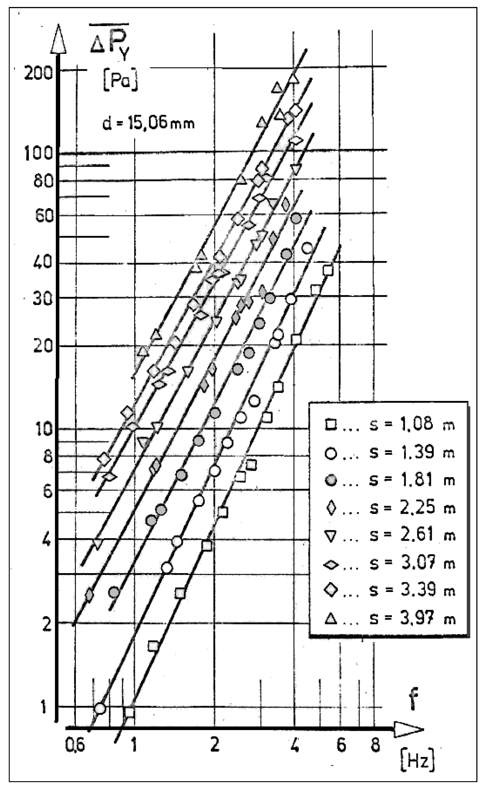
The piston diameter was 131 mm. Fixed to it was a f sliding yoke with vertical slot into which a slider moved vertically (designed so that any free play in the slot could be practically eliminated). In the circular hole in the slider was a cylindrical pivot positioned at an adjustable radial distance on an arm rotated by the motor. This allowed to adjust the piston stroke length z, Figure 8. In the experiment, the eight adjusted lengths were between the minimum z = 14.3 mm and the maximum z = 52.4 mm. The design was robust, aiming at easy manufacturing and eliminating all free plays. This resulted in moving a large mass of quite heavy mechanical components together with the piston. Their inertia limited the achievable frequency of oscillation to rather low values, with maxima near to f ~4 Hz (shorter strokes z allowing slightly higher values up to f ~ 5 Hz).
The main measured quantity was the time-mean pressure difference
between the barometric pressure Pb in the surrounding atmosphere and the time-mean pressure value inside the vessel. This vessel was large, with a volume V = 120 litres, as shown in Figure 8, so large that the air pressure pulsation was fully damped. The time-mean pressure difference (1) was read on an alcohol-filled inclined-tube micromanometer. The values were not large, and there was no doubt that with an oscillator capable of operating at higher frequency, the rectification performance could be higher (in the slow motion, too much air was lost by escaping back at and near the piston dead-end positions). However, the purpose of the experiments here discussed was not achieving a top performance but identifying the basic laws of the rectification. The three components of the setup—piston-type generator, rectifier, and settling vessel—were mutually connected by garden hoses made of polymer material, nominally of 1” inner diameter, as shown in Figure 8.
In total, eight measurement runs were made, differing in the length of the piston stroke z. During each of these runs, the frequency of the piston motion was gradually increased in a stepwise manner. Based on the ideas in [4,16], the representative length scale of the alternating flow generated by the piston-type generator is the length s of the "extruded" fluid column:
where Fn (m2) is the cross-sectional area of the nozzle exit, while Fp (m2) is the area of the piston front surface. The values s are listed in Figure 9, where they are seen to be roughly a decimal order of magnitude longer than the diameter of the nozzle [16] exit (cf. Figure 4). This makes somewhat questionable the above-mentioned hypothesis of a close relation with the rectification effect in synthetic jets [15,16] based on the formation of synthetic jets. Here, with the long s, the vortex rings, if they are of any importance at all, can be generated only at the start and end of the piston stroke.
s = z·Fp/Fn
2.3. Measurement Results
The results of the performed measurements are presented in the diagram pressure in Figure 9. The values of the measured pressure differences are plotted as a function of the piston periodic motion frequency f. In the logarithmic co-ordinates used in Figure 9, the data points of all eight runs may be fitted by straight lines of slope 2.0, with a quite small scatter. This suggests properties similar to those of many hydraulic components—typically nozzles [16]—where this slope leads to a constant (or nearly constant) Euler number
where v [m3/kg] is the specific volume of the fluid (in the experiments with air, the mean value was v = 0.834 m3/kg), and ŵ (m/s) is the velocity amplitude of the alternating nozzle exit flow. Neglecting compressibility, this velocity is computed as
ŵ = f·s
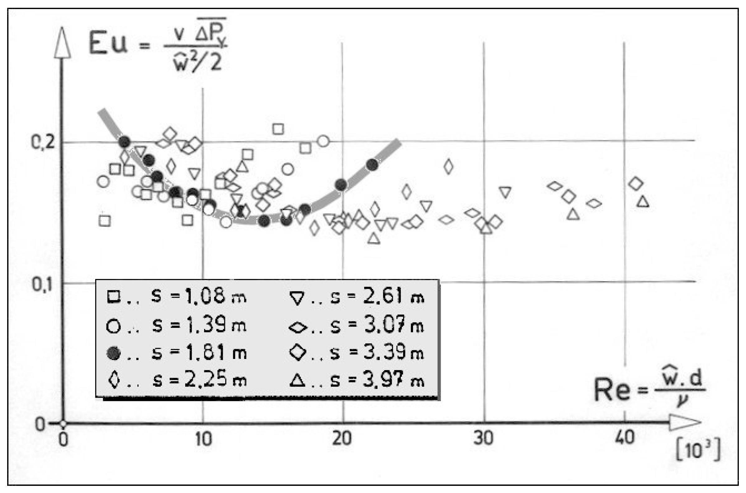
Of course, nozzles and similar devices typically show a slight dependence of Eu on the Reynolds number of the flow, which for alternating flows [15,20], is usually defined as
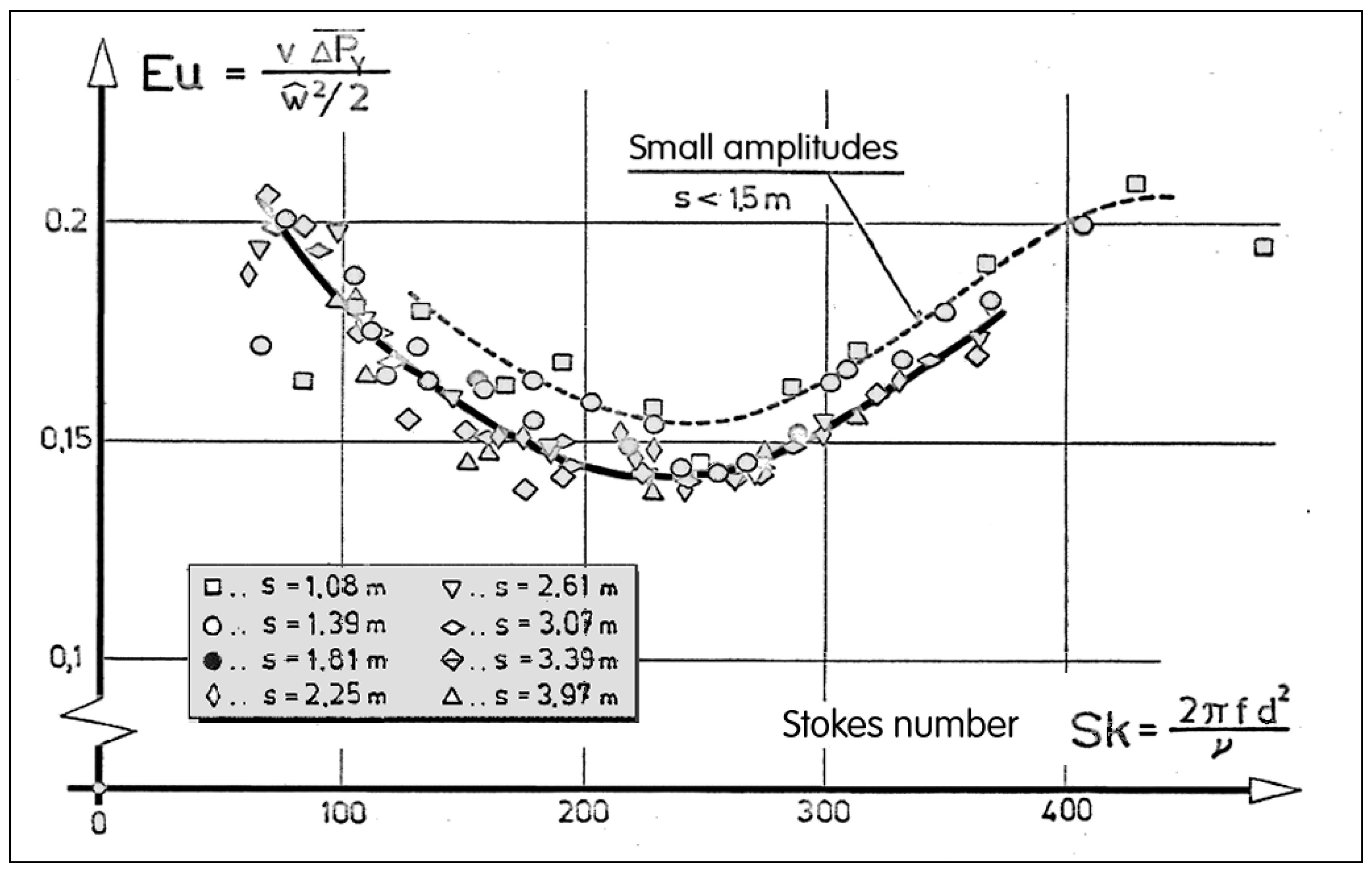
where d is the nozzle exit diameter (Figure 4), and (m2/s) is the viscosity of the fluid. The dependence Eu = f (Re) calculated from the data in Figure 9 is plotted in Figure 10. Indeed, the Eu values do not vary so much, and the variations are discarded as mere experimental scatter. Admittedly, the Eu values in Figure 10 are rather small, less than Eu = ~ 0.2, suggesting a somewhat low velocity-to-pressure conversion efficiency, but this was not considered an important fact in the research here discussed, aimed at explaining the basic phenomena and not at optimising the properties. More consequential observation are the recognisable general trends of the data for each of the frequencies, as shown in Figure 10. A closer observation revealed that the impression of the large scatter was wrong: the values of Eu = f (Re) for different s actually do not vary in a stochastic manner but follow a coherent law. This is shown in Figure 10 by the data indicated by the black circle symbols. They are distributed so as to form a wide letter U, with the minimum in the centre of the data set. A similar dependence was seen for other data series. The impression of the large scatter was caused by horizontal shifts and larger widths of the individual data sets. After re-plotting, a universal character of the dependences emerged, as shown in Figure 11. The variable plotted there on the horizontal co-ordinate is the Stokes number (product of Reynolds and Strouhal [21] numbers multiplied by 2).
All data for all experimental runs followed a distribution characterized by the minimum roughly located in the middle of the range of measurements, at Sk 250. This behaviour is explained by resonance. The translating pressure waves at the resonant conditions apparently allowed the pressure in the vessel to escape through the secondary inlet of the rectifier into the atmosphere. The depression at the minimum in Figure 11 was quite shallow (note the space left at the bottom of the vertical coordinate), obviously because of the strong damping of the resonance by friction. Indeed, a somewhat surprising effect was found prior to the actual measurements when the measured output pressure became slightly larger, following a slightly increase of the damping by the fluidic resistor located at the entrance into the settling chamber (cf. Figure 8), suppressing the amplitudes of the resonance.
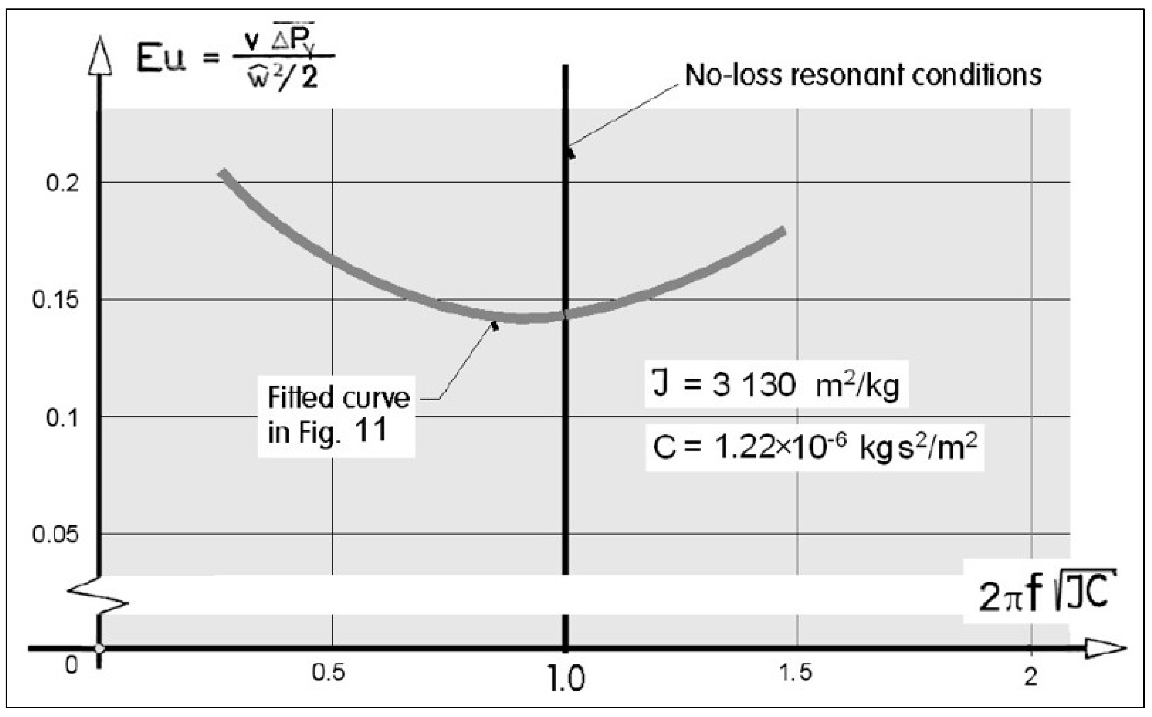
2.4. Behaviour Law for the Rectifier Model
Of course, resonance should be avoided in rectifier applications to avoid the minimum, by setting the operation Stokes number either below Sk 100 or above Sk 400. To make certain that the observed shape of the curve in Figure 11 was indeed a result of fluidic resonance, it was useful to evaluate the resonant condition by approximate analysis. As described in [22], the natural frequency oscillation in a fluidic circuit module with accumulation vessels at both ends of a connecting tube may be computed, especially in simplified conditions neglecting the losses. Moreover, the situation was additionally simplified by the presence of only one vessel—the other end of the tube being replaced by the atmosphere, with capacitance infinitely large.
The behaviour of a gas periodically compressed inside a constant-volume vessel is characterised by the capacitance C (kg s2/m2), while the unsteady (accelerated and decelerated gas flow in the tube) is characterised by the inertance J (m2/kg).
The capacitance C of a vessel [23] containing M kilograms of gas defines how forcing into the vessel an additional small mass dM increases the difference in specific energy de (the difference between the vessel and the atmosphere):
The inertance J indicates how large the increase of specific energy difference between the tube ends e caused by the acceleration of the mass flow rate inside the tube is. The otherwise positive difference value between the beginning and the end of the pipe is, in this case, negative because, here, the conditions inside the atmosphere in the upstream end are taken as the reference (while the conditions in the accumulation vessel are variable).
Differentiating Equation (5) with respect to time leads to
while differentiating the definition of inertance in Equation (8) leads to
By equating Equations (9) and (10), the equation of the mass flow rate oscillation is
It is useful to introduce dimensionless variables: the instantaneous mass flow rate is related to the initial value at the beginning of the oscillation
and the time t is related to the characteristic time tchar
where
The oscillation equation in relative coordinates is thus
with solution
The oscillation period is in the relative coordinates
so that the resonant frequency is
Of course, for a highly damped resonance (Figure 11), the resonant frequency is lower than this value, but not substantially. By evaluating, at least approximately, the characterisation quantities J and C, it is possible to determine whether the explanation of the behaviour by fluidic resonator properties is reasonable.
The capacitance of the atmosphere is negligible, and it may be plausible at this stage to neglect it together with the compressibility of the air inside the connecting hose. It is thus acceptable to consider only the periodic accumulation of air inside the settling vessel (Figure 8), of volume
where, with the specific volume v = 0.834 m3/kg, the mass of air inside is M = 0.144 kg.
V = 0.120 m3
The accumulation capacitance [20] is
where k is a polytropic exponent [18] with values between k = 1, for very slow isothermal changes of state, and k = 1.4 for very fast, adiabatic processes (so fast that there is not enough time for attaining thermal equilibrium). In the present case of a rather slow operating alternator, it may be acceptable to assume the equilibrium value k = 1. The gas constant of air (assuming a value slightly higher than the standard textbook value, due to air humidity) was here r = 288 J/(kg·K), so that at Pb = 101.3 kPa and with T = 293.2 K, the capacitance of the settling vessel according to Equation (21) was near to
C = M / (k·r·T )
C = 1.22 × 10⁻⁶ kg·s2/m2
The expression for the inertance J of a constant-diameter tube of cross-sectional area F (m2) [19] and length l (m) is
J = v·l/F
For the approximate evaluation of pressure waves propagating between the atmosphere and the vessel in resonance, it may suffice to consider the inertances of (a) the interconnection hose with 25.4 mm internal diameter and the length lhose 1.8 m—and the series-connected (b) annular space of the secondary inlet around the nozzle in the rectifier. The latter was approximately an lsecond 0.127 m-long segment between the outer diameter (29 mm, Figure 4) and the inner diameter (21 mm). This means a cross-sectional area Fsecond = 0.314 × 10⁻³ m2.
The total inertance is the sum
of Jsecond = 339 m2/kg and Jhose = 2800 m2/kg, with the total
J = Jsecond + Jhose
J = 3130 m2/kg
Inserting Equations (19) and (22) into Equation (16) results in
fres = 2.6 Hz
After plotting in comparison with the experimental data (as they are presented in Figure 9) the results were concordant, as shown in Figure 12. The small difference between the resonant frequency computed above and the minimum of the curve fitted to the data points is reasonably explained by the shift of the curve extreme due to losses (which, in Equations (11) and (18) were not taken into account).
3. Potential Applications
3.1. Discontinuing a Reaction in an Emergency Situation
One of the useful applications is keeping a dangerous liquid inside a reactor from which, as described in [3], it leaves by the absolutely reliable gravitation action in emergency situation a liquid such as, e.g., a coolant. The configuration, presented in Figure 13, consists of a vertical column into the bottom of which is generated pressure by the rectifier output. This opposes the tendency of the dangerous liquid to leave the reactor if there is no reason for operation discontinuation. The necessary alternating flow driving power for the rectifier is transported across the protective barrier–which surrounds the liquid and maintains it inaccessible.
A possible application may be in nuclear engineering or in the case of a chemical reaction that is so strongly exothermic that it requires permanent cooling by a circulating coolant. In emergency situations like, e.g., in the case of failure of the electric power supplied to the cooling system, the reaction must be stopped for safety reasons. The alternating flow generator is also electrically driven so that in such a situation it also stops. This allows the liquid to flow away from the reactor by gravitation. It is then accumulated in the storage vessel, at the bottom of which the rectifier is located. The illustration in Figure 14, taken from [3], shows the geometry of the fluidic device used in the safety tests. The same safety requirement—discontinuing the reaction by removal of the critically important dangerous liquid—is presented in Figure 15. Shown there are two situations referring to the reaction between the reactants A and B. On the left, the standard operation condition with alternating input flow into the rectifier is depicted, on the right, the liquid is removed from the reactor and retained in the storage vessel while the reaction is discontinued.
Of course, because of the slow motion in the available piston-type generator, the absolute pressure difference values presented in the experimental results in Figure 9 were very small, but this was solely the consequence of frequency limitations of the used alternator. The experiments clearly did not indicate any physical limit for design of the device with much larger output pressure levels.
3.2. Generating Vacuum in a Dangerous Space
The rectifier generates a pressure difference between the secondary (radial) fluid inlet on the left and the exit from the mixing tube on the right. In the applications discussed in Figure 11, Figure 12 and Figure 13, the radial inlet was kept at the constant atmospheric pressure. A higher pressure in the mixing tube exit was applied. It may be, however, also useful to reverse the operation: keeping the mixing tube exit at the atmospheric level and employing the vacuum in the secondary inlet. Figure 16 presents schematically an example in which (partial) vacuum is used in drying the substance supplied into the vacuum vessel in a mixture or with water. The vacuum is increased by providing the flow exit with a diffuser.
3.3. Impinging Jet of a Dangerous Fluid
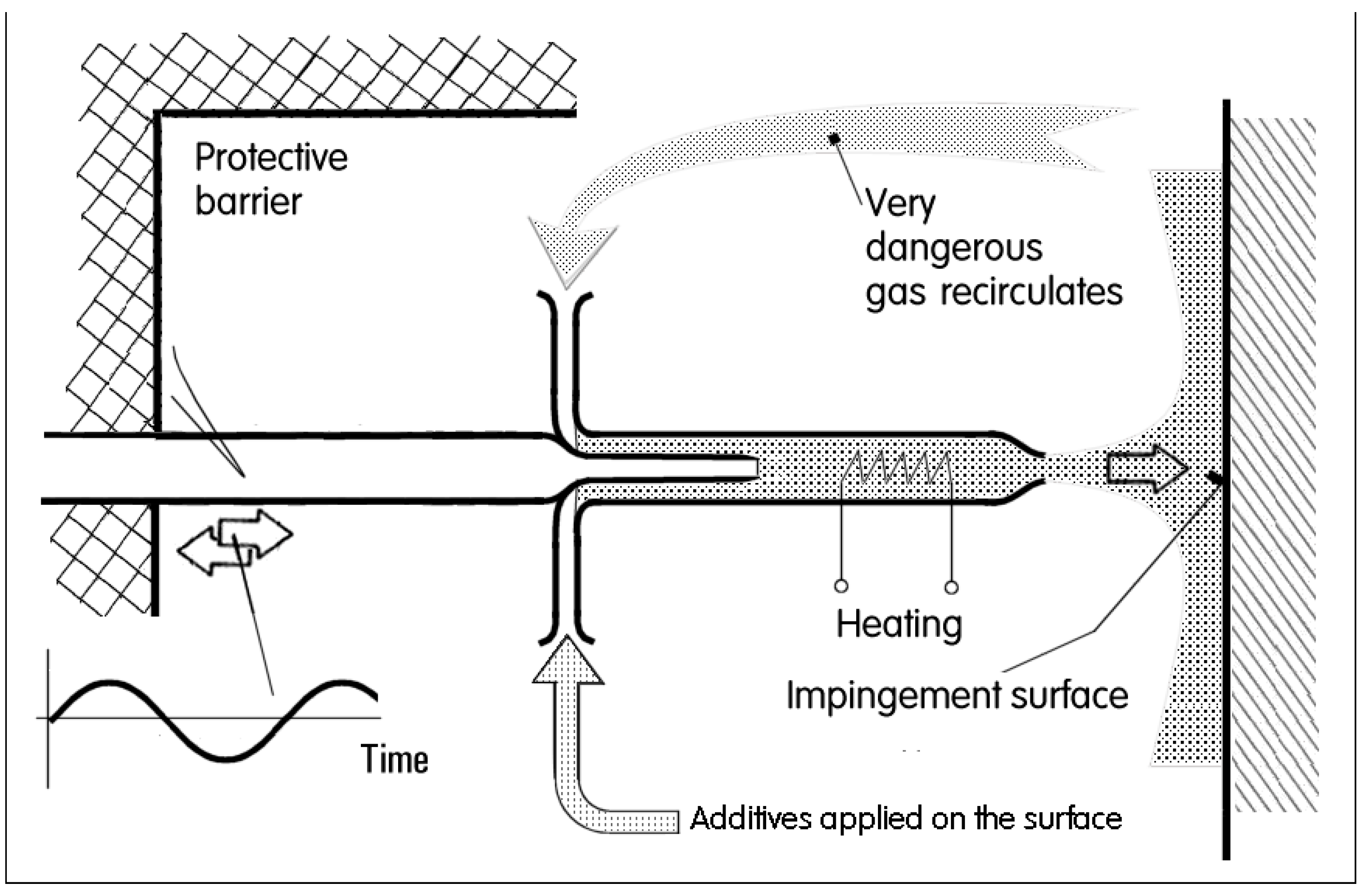
In the application examples presented above in Figure 11, Figure 12, Figure 13 and Figure 14, the rectifier was used for the generation of a pressure difference between two terminals (while the third terminal was used to bring in the driving alternating flow). This is not the only alternative. Instead of developments towards achieving large pressure difference, it is possible to concentrate on generating a large steady component of output flow (blowing out from the main exit terminal and sucked into the secondary terminal from a large tank). The character of the generated flow is that of a jet issuing from one terminal which serves as the nozzle [16]. In the example presented in Figure 17, the jet impinges upon a processed surface. This is usually done for heat and/or mass transfer because impinging jets [14] are generally known to be able to achieve the highest transfer rate values. Again, as in the previous examples, in this case the jet driven by the alternating input flow may offer the extreme levels of safety in handling dangerous fluids or substances.
4. Multi-phase Alternatives
The configurations of the rectifier discussed in the previous paper sections are those which were discovered and tested experimentally. Their rectification effectiveness, as is seen from the Euler number values in Figure 8, Figure 9 and Figure 10, was not particularly high. This was not considered a substantial drawback because in the discussed application, it would be otherwise impossible to benefit from the advantages offered by the isolation of the dangerous fluid and the alternating-flow power transfer. The reason for the not impressive efficiency is the negative driving flow, in opposing direction, acting during more or less one half of the oscillation period. It is obvious that the efficiency may be improved really significantly if the return action of the driving is eliminated (or at least suppressed) by several mutual phase-shifted pulsations in the layouts. There are three such flow phases in Figure 18, mutually shifted by /3 radians, and two phases shifted by radians in Figure 19. The negative effect, i.e., the suction of fluid back into the driving inlet, is suppressed by a coexistent positive outflow from another nozzle. The nozzles may be arranged in parallel, as is the case in Figure 18, or in series, as presented in Figure 19.
5. Conclusions
An unusual fluidic rectification phenomenon and its potential uses are discussed. Discovered and described in [3], it was since then practically forgotten, despite several interesting application possibilities, especially those ensuring safety in handling dangerous fluids. In some respects, the discussed device was a precursors of synthetic jets [15,16], differing from them in the flow configuration. Synthetic jets are characterized by generation of vortex rings travelling in a free space while here the nozzle flow issues into the constant-diameter mixing tube. In particular, the rectifier may be employed in power transfer across a protective barrier behind which a dangerous fluid is handled inside an inaccessible confined space. Also for ensuring the full 100 % safety, there is behind the protective barrier an absence of moving or deformed mechanical components. The power driven by alternating flow exhibits a combination of unique properties, otherwise not obtainable.
The main results of the experiments presented here are of qualitative character. They are as follows:
- (1)
- Verification of the existence of a new rectifier principle,
- (2)
- Demonstration of the generated time-mean pressure in the device output terminal (pressure difference relative to the atmospheric input), and
- (3)
- Description of several alternative engineering applications, which justify further investigations of the device.
Among the quantitative results, worth noting are also:
With the only a very low-frequency input generator available for the tests (note that the generated time-mean output pressure is demonstrated to increase rapidly with an increasing oscillation frequency), it would be obviously futile at this stage to attempt a performance optimisation, as this would require a financially extensive research project considering the very large number of geometric parameters of the device that would require being varied.
Funding
Author’s experimental research was supported by grant 17-08218S obtained from GAČR, the Grant Agency of the Czech Republic. He was also a recipient of institutional support RVO: 61388998.
Conflicts of Interest
The author declares that there are no conflict of interest regarding the publication of this paper.
Nomenclature
| C | kg·s2/m2 | Capacitance |
| D | m | Mixing tube diameter |
| d | m | Nozzle exit diameter |
| Eu | Euler number | |
| F | m2 | Cross-sectional area |
| Fsecond | m2 | Annular inlet cross-sectional area |
| fres | Hz | Resonant frequency of pressure waves |
| f | Hz | Frequency of piston motion |
| Jhose | m2/kg | nertance of connecting hose |
| Jsecond | m2/kg | Inertance of annular space |
| J | m2/kg | Inertance |
| l | m | Tube or hole length |
| M | kg | Mass of gas |
| P | Pa | Pressure |
| Pb | Pa | Barometric pressure |
| PY | Pa | Output pressure |
| Pa | Time-mean output pressure difference | |
| r | J/kg·K | Gas constant |
| Re | Reynolds number | |
| Sk | Stokes number | |
| s | m | Ideal length of displaced gas column |
| T | K | Temperature |
| V | m3 | Gas volume |
| v | m3/kg | Gas specific volume |
| ŵ | m/s | Velocity amplitude |
| z | m | Piston stroke |
| v | m2/s | Viscosity |
References
- Tippetts, J.R.; Swithenbank, J. Fluidic flow control devices and pumping systems. U.S. Patent 4021146, October 1974. Available online: https://patents.google.com/patent/US4021146/en (accessed on 14 August 2019).
- Stutely, J.R.; Walkden, A.J. Improvements in or relating to pumps. UK Patent 1132442, October 1968. Available online: https://www.osti.gov/biblio/4809332-improvements-relating-pumps (accessed on 14 August 2019).
- Tesař, V. Active Fluidic Turn-Down Valve. CZ Patent 212802, March 1980. Available online: https://isdv.upv.cz/doc/FullFiles/Patents/FullDocuments/212/212802.pdf (accessed on 14 August 2019).
- Tesař, V. Pump for extremely dangerous liquids. Chem. Eng. Res. Des. 2011, 89, 940. [Google Scholar] [CrossRef]
- Tesař, V. Safe pumping of hazardous liquids—A survey of no-moving-part pump principles. Chem. Eng. J. 2011, 168, 23. [Google Scholar] [CrossRef]
- Tesař, V. Development of a no-moving-part blower for difficult operating conditions. Chem. Eng. Res. Des. 2013, 91, 2401. [Google Scholar] [CrossRef]
- Tesař, V. Taxonomic trees of fluidic oscillators. Eur. Phys. J. 2017, 143, 02128. [Google Scholar] [CrossRef] [Green Version]
- Tesla, N. Valvular Conduit. U.S. Patent 1329559, February 1916. Available online: http://www.tfcbooks.com/patents/1329559.htm (accessed on 14 August 2019).
- Rexford, D.S. Fluidic Rectifier Device. U.S. Patent 3516428, September 1966. Available online: https://patents.google.com/patent/US3516428 (accessed on 14 August 2019).
- Romiti, A.; Belforte, G. Respiratore artificiale an controllo dell’inspirazione. Ric. Sci. Cons. Naz. Ticerce 1970, 40. Available online: https://books.google.cz/books?id=AegkBAAAQBAJ&pg=PA23&lpg=PA23&dq=Romiti+Belforte+Respirator&source=bl&ots=t4Cws-doB1&sig=ACfU3U2J-C57qVZd6eR0F6mYiD1ekb1RUg&hl=cs&sa=X&ved=2ahUKEwjsy4G99__jAhXUwsQBHd85BIEQ6AEwBHoECAgQAQ#v=onepage&q=Romiti%20Belforte%20Respirator&f=false (accessed on 14 August 2019).
- Drzewiecki, T.M.; Manion, F. Axisymmetric Fluidic Throttling Flow Controller. U.S. Patent 4108721, June 1977. Available online: https://patents.google.com/patent/US4108721 (accessed on 14 August 2019).
- Tippetts, J.R. A fluidic pump for use in nuclear fuel reprocessing. In Proceedings of the 5th International Fluid Power Symposium, Durham, UK, 12–14 April 1978. [Google Scholar]
- Tippetts, J.R.; Priestman, G.H.; Thompson, D. Developments in power fluidics for application in nuclear plant. Trans. ASME 1981, 103, 342–351. [Google Scholar] [CrossRef]
- Coanda, H. Device for deflecting a stream of elastic fluid projected into an elastic fluid. U.S. Patent 2052869, 14 October 1934. [Google Scholar]
- Tesař, V. Configurations of fluidic actuators for generating hybrid-synthetic jets. Sens. Actuators A Phys. 2007, 138, 394. [Google Scholar] [CrossRef]
- Tesař, V.; Zhong, S. Efficiency of synthetic jet generation. Trans. Aeronaut. Astronaut. Soc. Repub. China 2003, 35, 45. [Google Scholar]
- Vortex Rings and Jets, Recent Development in Near-Field Dynamics; Springer Science + Business Media: Singapore, 2015.
- Tesař, V. Characterization of two-terminal devices. In Microfluidics: History, Theory, and Applications; Zimmerman, W.B.J., Ed.; CISM Courses and Lectures No. 466; Springer: New York, NY, USA, 2006; pp. 223–253. [Google Scholar]
- Tesař, V. Recent advances in characterisation of subsonic axisymmetric nozzles. Eur. J. Phys. 2018, 174. [Google Scholar] [CrossRef]
- Tesař, V. Effective hydraulic resistance of actuator nozzle generating a periodic jet. Sens. Actuators A Phys. 2012, 179, 211–222. [Google Scholar] [CrossRef]
- Strouhal, V. Über eine besondere Art der Tonerregnung. Vortr. Phys.-Med. Gesselschaft Würzburg 1878, 241, 216–251. [Google Scholar]
- Section 13.2.1. In Microfluidics: History, Theory and Applications; Zimmerman, W. (Ed.) CISM courses and lectures No. 466; Springer: New York, NY, USA, 2006. [Google Scholar]
- Tesař, V. Variations of fluidic capacitance in the course of transient state changes. Fluid. Q. 1979, 11, 371321. [Google Scholar]
Figure 1.
Representation of the transferring power into an inaccessible space behind a protective barrier, where an is handled an extremely dangerous fluid. The alternating input flow into the no-moving-parts fluidic rectifier is the only way to securing behind the barrier both full safety and no need of moved (piston) or deformed (springs) mechanical components behind the barrier.

Figure 2.
Schematic representation of the rectifier internal flows during the delivery stroke. In the low loading case A, the large output terminal flow rate is due to the jet’s pumping effect. With the output terminal blocked by the load, as in B, the return flow is limited by directing the flow past the sharp edge of the nozzle exit.

Figure 3.
Schematic representation of the rectifier flows in the suction stroke period. (a) In the middle of the stroke, (b) towards the stroke end. During the cycle halves, vortex rings acting in a manner similar to those in synthetic jets are generated.
Figure 3.
Schematic representation of the rectifier flows in the suction stroke period. (a) In the middle of the stroke, (b) towards the stroke end. During the cycle halves, vortex rings acting in a manner similar to those in synthetic jets are generated.

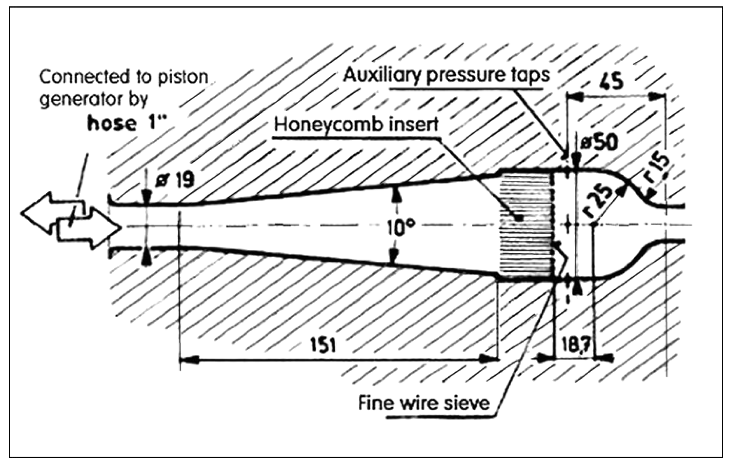
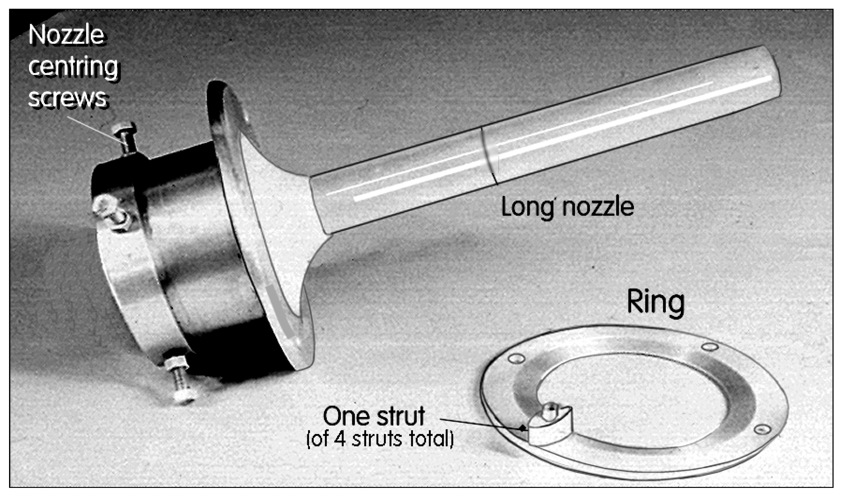
Figure 4.
Geometry of the investigated fluidic rectifier. The alternating flow was supplied to the left into the central primary nozzle. The secondary annular nozzle was supplied with the air sucked in through the radial inlet (10 mm-wide) from the atmosphere. In the experiments presented in Figure 8 and Figure 9, the flow rate through the output terminal was zero, as in Figure 2B.

Figure 5.
Geometry of the inlet into the primary nozzle. Initial considerations of precise flow measurements in the mixing tube called for a very regular supply flow, stabilised by honeycomb, sieve, and area contraction seen in this illustrations.
Figure 5.
Geometry of the inlet into the primary nozzle. Initial considerations of precise flow measurements in the mixing tube called for a very regular supply flow, stabilised by honeycomb, sieve, and area contraction seen in this illustrations.

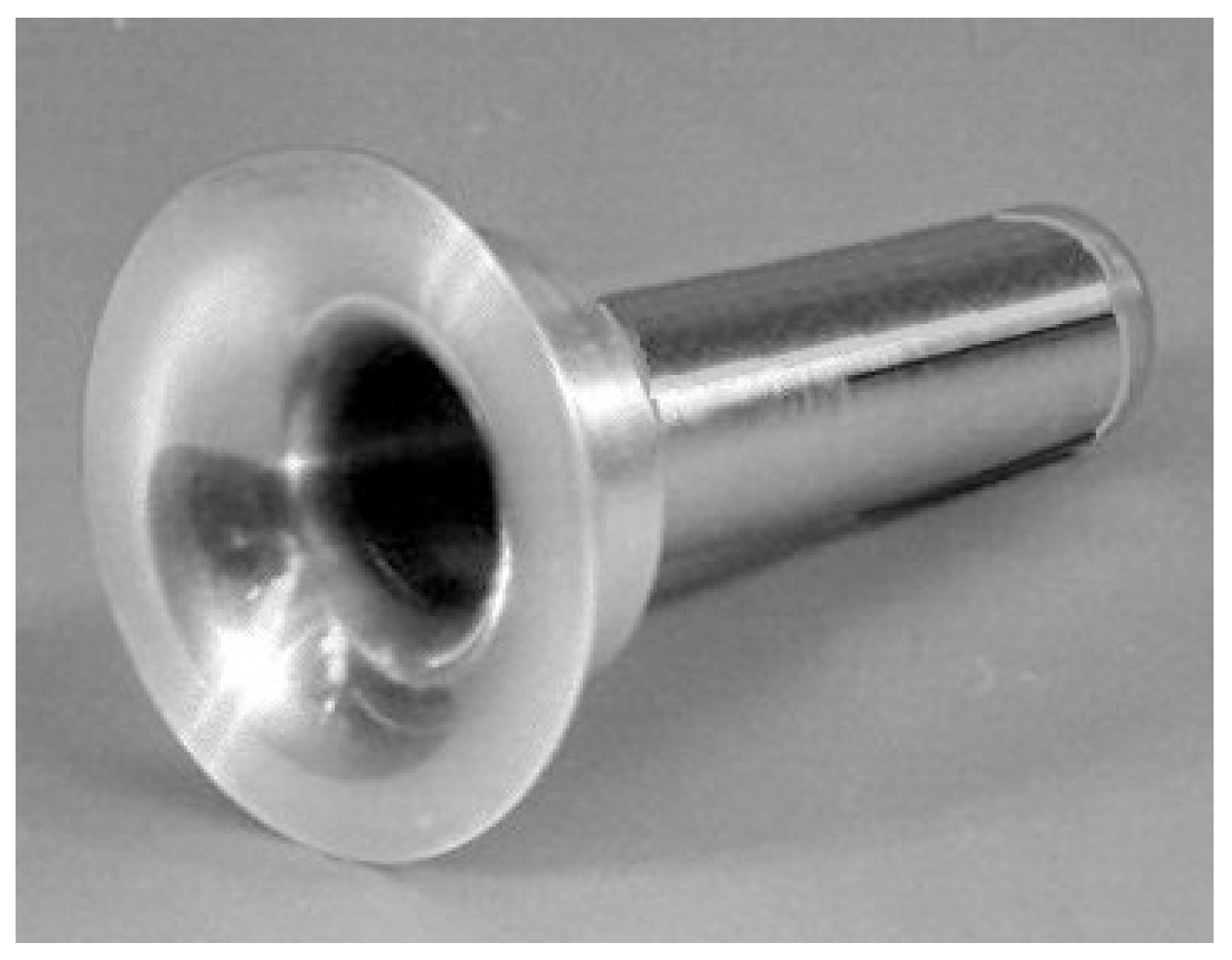
Figure 6.
Photograph of the outer part N (cf. Figure 4) of the radial inflow into the annular secondary inlet into the mixing tube.
Figure 6.
Photograph of the outer part N (cf. Figure 4) of the radial inflow into the annular secondary inlet into the mixing tube.

Figure 7.
Photograph of the long central nozzle (inner part M, cf. Figure 4). It defines the other annular wall of the radial inflow into the mixing tube.
Figure 7.
Photograph of the long central nozzle (inner part M, cf. Figure 4). It defines the other annular wall of the radial inflow into the mixing tube.

Figure 8.
Schematic representation of the rectification experiment. The time-mean output flow from the mixing tube is zero. The pressure inside the settling vessel due to the rectification effect was measured by the manometer between the settling chamber and the atmosphere. The Scotch-yoke piston-type alternator generates a purely harmonic flow at adjustable frequency.

Figure 9.
Measured time-mean pressure difference in the settling vessel relative to the atmosphere, here plotted as a function of the piston motion frequency f. The distance s is the piston stroke multiplied by the ratio of the piston and nozzle areas.
Figure 9.
Measured time-mean pressure difference in the settling vessel relative to the atmosphere, here plotted as a function of the piston motion frequency f. The distance s is the piston stroke multiplied by the ratio of the piston and nozzle areas.

Figure 10.
Euler number Eu of the measured pressure in the settling vessel plotted as a function the nozzle exit flow Reynolds number Re.
Figure 10.
Euler number Eu of the measured pressure in the settling vessel plotted as a function the nozzle exit flow Reynolds number Re.

Figure 11.
The universal law for the zero flow conditions in the rectifier, obtained by plotting the Euler number as a function of the Stokes number.
Figure 11.
The universal law for the zero flow conditions in the rectifier, obtained by plotting the Euler number as a function of the Stokes number.

Figure 12.
The universal law curve with the characteristic local minimum. The shape of this curve is explained by the resonance Equation (25) of the air accumulated in the settling vessel and accelerated in the inlet annular inlet as well as the interconnection hose.
Figure 12.
The universal law curve with the characteristic local minimum. The shape of this curve is explained by the resonance Equation (25) of the air accumulated in the settling vessel and accelerated in the inlet annular inlet as well as the interconnection hose.

Figure 13.
Application of the pressure generated by rectification of the alternating driving flow. In emergency situations, such as a coolant loss due to electricity failure, the liquid necessary for running the reaction leaves the reactor under gravity (picture from Patent document [3]).
Figure 13.
Application of the pressure generated by rectification of the alternating driving flow. In emergency situations, such as a coolant loss due to electricity failure, the liquid necessary for running the reaction leaves the reactor under gravity (picture from Patent document [3]).

Figure 14.
Another picture from [3] shows the rectifier used in an analogy to Figure 13 to stop the reaction in emergency situations. The liquid from the riser pipe is then kept in the storage vessel.

Figure 15.
Reaction between two dangerous reactants A and B is discontinued in emergency situations by removal of the mediator liquid (e.g., a catalyst). This liquid is normally kept inside the reactor by the pressure generated by rectifying the input pulsation.
Figure 15.
Reaction between two dangerous reactants A and B is discontinued in emergency situations by removal of the mediator liquid (e.g., a catalyst). This liquid is normally kept inside the reactor by the pressure generated by rectifying the input pulsation.

Figure 16.
Drying in vacuum generated in the rectifier and its diffuser-shaped mixing tube.

Figure 17.
Characteristics of the rectification effect at the other end of the reactor output loading. The dangerous fluid is accelerated in the mixing tube by the rectified alternating flow and forms an impinging jet.
Figure 17.
Characteristics of the rectification effect at the other end of the reactor output loading. The dangerous fluid is accelerated in the mixing tube by the rectified alternating flow and forms an impinging jet.

Figure 18.
Schematic representation of a device driving a fluid carrying extremely dangerous pathogens to an inaccessible space. Fluid motion is maintained by a three-phase alternating flow, with nozzles in the rectifier arranged in parallel.
Figure 18.
Schematic representation of a device driving a fluid carrying extremely dangerous pathogens to an inaccessible space. Fluid motion is maintained by a three-phase alternating flow, with nozzles in the rectifier arranged in parallel.

Figure 19.
Alternative two-phase driving of the rectified flow with the nozzles arranged in series.

© 2019 by the author. Licensee MDPI, Basel, Switzerland. This article is an open access article distributed under the terms and conditions of the Creative Commons Attribution (CC BY) license (http://creativecommons.org/licenses/by/4.0/).
Share and Cite
MDPI and ACS Style
Tesař, V. Active Fluidic Turn-Down Rectifier. Energies 2019, 12, 3181. https://doi.org/10.3390/en12163181
AMA Style
Tesař V. Active Fluidic Turn-Down Rectifier. Energies. 2019; 12(16):3181. https://doi.org/10.3390/en12163181
Chicago/Turabian StyleTesař, Václav. 2019. "Active Fluidic Turn-Down Rectifier" Energies 12, no. 16: 3181. https://doi.org/10.3390/en12163181
Note that from the first issue of 2016, this journal uses article numbers instead of page numbers. See further details here.