Article

Desiccant-Assisted Air Conditioning System Relying on Solar and Geothermal Energy during Summer and Winter †

Institute of Engineering Thermodynamics, Hamburg University of Technology, 21073 Hamburg, Germany
*
Author to whom correspondence should be addressed.
This paper is an extended version of our paper published in the 2018 International Sustainable Energy Conference (ISEC), Congress Graz, Austria, 3–5 October 2018.
Energies 2019, 12(16), 3175; https://doi.org/10.3390/en12163175
Submission received: 19 July 2019 / Revised: 14 August 2019 / Accepted: 15 August 2019 / Published: 19 August 2019
(This article belongs to the Special Issue Alternative Energy Systems in Buildings)

Abstract

:
At Hamburg University of Technology the combination of an open cycle desiccant-assisted air conditioning system and a geothermal system is investigated in the framework of different research projects for several years. The objective of this study is to investigate the energy efficiency of the overall system and to evaluate the geothermal system during summer and winter mode, based on data measured for a temperate climate region. Monitoring results of the performance for dehumidification and remoistening of supply air are presented. Furthermore, the investigated system is compared to reference air conditioning processes. During summer mode, an average dehumidification efficiency of 1.15 is achieved. The electrical energy savings compared to a conventional reference system sum up to 50% for the investigated cooling period. System operation during winter shows an average moisture recovery efficiency of 0.75. The electrical energy demand for air humidification is reduced by 50% compared to a system with electric isothermal air humidification. The geothermal system is operated efficiently throughout the year for cooling and heating application. Besides the energetic system evaluation, measured data regarding the soil temperature and thermal comfort are presented.

Graphical Abstract

1. Introduction

Due to increasing sales numbers and resulting energy demand for air conditioning as well as related CO2 emissions worldwide, energy efficient and more environmental friendly air conditioning is required [1]. According to the International Energy Agency (IEA), an increase of more than five billion air conditioning systems between the years of 2016 and 2050 is estimated for the commercial and residential stock [2]. That means more than a doubling of the currently installed units. Income growth in the developing and emerging countries, climate change and increased building energy standards cause this development for air conditioning [3,4]. Currently, air conditioning is responsible for around 20% of buildings’ electricity demand from a worldwide perspective [2]. Furthermore, heating, ventilation and air conditioning (HVAC) systems require the largest share of energy used in buildings. Thus, enhancing performance of conventional systems offers the opportunity to significantly reduce energy demand and related CO2 emissions, respectively [5].
Air conditioning systems are often used to provide comfortable indoor air conditions in general. Removing latent and sensible loads from outside air is usually required during summer to provide the desired indoor air conditions. Especially moisture removal accounts for peak loads of conventional air conditioning systems since it requires cooling process air below dew point temperature. Cooling and dehumidification are coupled necessarily due to the process itself. Required cooling capacities are often provided by electrical driven vapor compression cycles. In contrast, removal of sensible and latent loads is separated within a desiccant assisted air conditioning process. A desiccant material is used to remove latent loads from the process air stream. Thus, required cooling capacities are reduced, especially at high outside air humidity ratios. Shallow geothermal energy can be utilized to remove sensible loads from the process air stream. Utilizing the soil for cooling, an equalized energy balance of the soil is essential regarding long-term efficiency of the geothermal system. This can be improved by using a ground-coupled heat pump for heat supply during winter.

1.1. Desiccant Assisted Air Conditioning

Valkiloroaya et al. [6] presented an overview of different strategies and technologies to reduce energy demands related to air conditioning in general. Desiccant-assisted air conditioning has been found to be a promising alternative to conventional air conditioning processes relying on a vapor compression chiller in terms of reducing the electricity demand for air conditioning. From a global perspective, air conditioning systems are primarily used during summer operation, providing cooled and dehumidified air. Thus, a lot of different studies dealing with the improvement and evaluation of desiccant materials and different system configurations for dehumidification mode. Several studies provide overviews of different concepts for desiccant assisted air conditioning systems with both solid and liquid desiccant material [7,8,9,10,11]. Within the field of systems relying on a solid desiccant material, a considerable amount of studies investigate design and performance of desiccant wheels [12,13,14]. Desiccant assisted hybrid systems are known as system configuration relying on an open sorption process and closed-loop cooling circuit. Several studies have been undertaken to investigate energetic advantages of hybrid systems for different locations [15,16,17,18,19,20,21]. To further reduce the electrical energy demand related to air conditioning, shallow geothermal energy is shown as promising alternative and renewable heat sink [22,23,24,25].
With respect to full year operation, final energy demand for space heating is currently still higher than final energy demand for space cooling applications from a global perspective [4]. But even though winter mode is obviously an essential part of full year operation, especially for heating dominated regions, winter mode as well as full year operation of desiccant assisted air conditioning systems are addressed only in few studies. Beccali et al. [26] investigated a hybrid system during summer and winter operation experimentally for the climate conditions of southern Italy. The presented system is relying on solar thermal heat supply with additional gas boiler backup system; a compression chiller is utilized for cooling. During summer operation, a reduction in primary energy demand of nearly 50% was achieved compared to a conventional reference system. Required information about system performance regarding moisture control in winter mode are not provided. De Antonellis et al. [27] investigated experimentally and numerically humidification of outside air using a desiccant wheel with silica gel coating for Mediterranean winter conditions. The authors investigated energy demand and occupants’ discomfort for the considered system configuration and highlight the dependence of air humidification performance and required regeneration air temperature. To further evaluate the system’s performance, a comparison with conventional humidification technologies is presented from an energetic point of view. Simulation results show reduced primary energy demand for air humidification using the proposed system compared to reference systems with adiabatic and electrical steam humidifiers for different working conditions. Compared to reference systems with steam to steam humidifier primary energy demand of the proposed system was increased for the considered boundary conditions. Kawamoto et al. [28] investigated the combination of a desiccant-assisted system and a heat pump that is used for heat supply on the regeneration air side experimentally in Japan. La et al. [29] examined a system configuration with solar thermal heat supply and one-rotor two-stage desiccant wheel for winter in Shanghai experimentally and numerically. The proposed system uses extract air from the conditioned space to humidify supply air preheated with solar thermal energy. The study shows significant increase in thermal comfort due to air humidification. Furthermore, the authors draw attention to the space requirements for solar collectors to improve thermal comfort. Full year operation of a desiccant- assisted evaporative system in Austria was investigated experimentally by Preisler and Brychta [30]. The investigated system achieved a reduction in primary energy demand of 60% in comparison to a reference system relying on a vapor compression chiller, considering full year operation. The authors outline high energy saving potentials of the investigated system, whereas details about the humidification process and boundary conditions of system comparison are not provided.

1.2. Air Dehumidification and Moisture Recovery

Regarding desiccant wheel performance in dehumidification and enthalpy recovery mode, Zhang and Niu [31] investigated different desiccant wheels numerically by means of a two-dimensional heat and mass transfer model. From their simulation results the authors conclude that the optimal rotational speed of a wheel used for dehumidification is much lower than optimal rotational speed of a wheel utilized for enthalpy recovery.
Increasing the moisture level of supply air is a sensitive but often little noticed comfort aspect during winter. Dry indoor air conditions can adversely affect occupants’ comfort, especially in modern buildings relying on mechanical ventilation without additional humidification systems during winter. Conventional air conditioning systems require additional components to achieve sufficient supply air humidity ratios. This is an advantage of desiccant assisted systems, because moisture recovery by means of the existing hygroscopic material is possible. A further hygienic advantage of desiccant assisted moisture recovery against conventional air conditioning relying on adiabatic or isothermal air humidification is the fact that no liquid or vaporous water is sprayed into the process air stream. Thus, emission of bacteria caused by air humidifiers as for example described by Strindehag and Josefsson [32] is avoided.

1.3. Previous and Ongoing Investigations of the Considered System

To the best of the authors’ knowledge there is no study investigating summer and winter operation of an air conditioning system relying on desiccant assisted dehumidification, enthalpy recovery and a ground-coupled heat pump for heating dominated climate conditions. In [33,34] the considered system is evaluated during summer operation mode, using a borehole heat exchanger (BHE) for cooling. The system is verified to be promising against conventional air conditioning systems in temperate climate regions. Furthermore, Speerforck et al. [35] proved applicability of the proposed system at different investigated locations by means of a dynamic system model using modeling language Modelica®. The authors investigated summer operation, whereas winter mode is not observed.
Within this study the geothermal and desiccant assisted system is investigated experimentally during summer and winter operation to show system performance throughout the year. Moisture control is achieved by a desiccant wheel (summer) or enthalpy wheel (winter) to improve indoor air conditions; sensible cooling loads are primarily covered by cooling ceilings, whereas heating loads are primarily covered by underfloor heating, respectively. In combination with a geothermal system, temperature levels of cooling ceilings and underfloor heating enable efficient operation of shallow geothermal energy in combination with a ground-coupled heat pump (GCHP) during winter. Regarding an equalized energy balance, utilizing the soil for cooling and heating is essential.
This study is structured into three parts. First, a short description of the investigated system, operation modes and data acquisition is provided. Afterwards, the performance and limitations of the investigated system are analyzed. Especially, performance of the air handling unit and the geothermal system are considered. The effects on indoor air conditions in terms of thermal comfort are investigated in detail. Additionally, the system is compared to different reference systems regarding electrical and thermal energy demands. Finally, the main findings are summarized and future research work is addressed. This study is an extension of Niemann et al. [36], providing a previous experimental analysis on summer and winter operation of the investigated system.

2. Materials and Methods

The investigated test facility is located on the campus of Hamburg University of Technology. Figure 1 shows some impressions of the installation and its relevant components. In total, the test facility consists of eight 20 ft. containers. The four containers on the lower floor contain the air handling unit and further technical installations. An office and conference room with a net floor space of 56 m² is located in the four upper containers. This area is used as reference room for the air conditioning system. System operation is investigated throughout the year.

2.1. Air Conditioning System

As shown in Figure 2, system layout of the installation can be divided basically into three subsystems in form of the reference room, the air handling unit and the hot and cold water circuit. The air handling unit is designed as hybrid system combining an open desiccant assisted air handling process with closed-loop heating and cooling circuits similar to the system presented by in [33,36].
A brief description of system operation in summer and winter mode is given for the sake of completeness. Summer and winter operation are considered separately according to [36]. Considering dehumidification mode during summer, outside air (oda) is dehumidified within a desiccant wheel (1→2) and precooled by a sensible rotating heat exchanger (2→3). Water vapor is accumulated at the hygroscopic coating of the desiccant wheel (DW); lithium chloride (LiCl) is used as desiccant. Afterwards, process air is finally cooled or heated to the desired supply air (sup) temperature within a sensible water to air heat exchanger (3→4). Extract air (eta) from the reference room is preheated (5→6) by the heat recovery wheel (HRW) and further heated to the required regeneration air temperature within another sensible water to air heat exchanger (6→7). Finally, eta is used to regenerate the desiccant material (7→8), before it is emitted to the environment in form of exhaust air (exa). To achieve efficient operation, different components of the air handling unit can be bypassed as shown in Figure 2. Thus, electricity demand of the fans is reduced for demand-oriented air conditioning.
Regarding winter operation, the desiccant wheel is operated as enthalpy wheel at higher rotational speed for coupled heat and mass transfer (1→2) relying on passive air humidification. Oda is remoistened and reheated within this process using the eta stream. If oda humidity is within comfort limits regarding humidity ratio, it is preheated using the regenerative heat exchanger (2→3); the desiccant wheel is bypassed in this case. Otherwise, the heat recovery wheel is not utilized. The reheater (3→4) is used to adjust process air to the desired sup temperature. Eta is either used for sensible heat recovery (5→6) or coupled heat and moisture recovery (7→8). The heater (6→7) is not operated in winter operation mode.
Both wheels have a diameter of 0.6 m. The reference room is connected to the air handling unit on the supply and extract air side for air exchange. Furthermore, to cover sensible heat and cooling loads directly, it is equipped with underfloor heating and cooling ceilings.
Desiccant assisted air conditioning enables the integration of shallow geothermal energy for cooling in summer due to the fact that the required temperature level for cooling applications is above dew point temperature at any time. Due to the capacity of the soil, a cold water storage is not integrated into the cold water circuit with respect to summer operation. Utilizing the geothermal system during full year operation as heat sink and heat source is essential for the reason of improving the annual energy balance of the soil as well as for the reason of maximizing the use of renewable energies around the year. Thus, heat supply during winter is primarily relying on a ground-coupled heat pump system ( Q ˙ GCHP , nom = 5.1   kW th at BW5/W30). Solar thermal energy is utilized as primary heat source during summer mode ( A STU = 20   m 2 ). A small-scale gas driven cogeneration (CHP) unit ( Q ˙ CHP , nom = 12.5   kW th , P CHP , nom = 5   kW el ) is used as backup system and to cover peak loads throughout the year. Integrating a stratified thermal storage system ( V = 1   m 3 ) into the hot water circuit enables heat supply and heat demand to be decoupled temporally.

2.2. Geothermal System

The geothermal system is built of a single double U-tube borehole heat exchanger (BHE), utilized as heat sink of the cold water circuit (summer) and heat source to supply the GCHP system (winter) as shown in Figure 2. With respect to the geothermal system itself, Figure 3 shows the structure of the soil at the drilling location and the design of the BHE. The thermistor string of an additional reference BHE (Ref) of the same type is used to analyze the impact of utilizing geothermal energy on the surrounding soil.
The soil primarily consists of micaceous clay. Nevertheless, for the first 18 m below ground surface fine, medium and coarse sands are present. A layer of till and silt is located underneath. There are no relevant ground water flows at the drilling location in general. Thermal conductivity of the grouting material is λ = 2   W   · m 1   · K 1 .

2.3. Data Acquisition

To characterize the status of working fluids within the overall process, all relevant parameters are measured and recorded. Table 1 provides an overview of the measurement characteristics for the entire process. Air states are labeled according to Figure 2.
In order to take inhomogeneity within the air streams into account, flow averaging is applied according to Slayzak and Ryan [37]. Electricity demand of each component according to Figure 2 is measured separately. Measurement devices in use and related uncertainties are listed in Table 2. All measured data are recorded every minute. A data acquisition system in connection with controlling software is used to control and regulate the entire system.
Due to drifting effects of capacitive humidity sensors (typical 1% rh per year), the resilience of derived quantities, energy and mass balances gets more and more limited as time goes by. Thus, these sensors are recalibrated once a year. The calibration method is relying on 36 set point combinations of temperature and relative humidity in the range of relevant temperatures and humidity ratios.

3. Results and Discussion

The results presented in this study are based on measured data of the cooling period from June till September in 2016 and the following heating period from January till March in 2017. During the considered periods the test facility was operated from 7 am to 10 pm every day of the week. Transition periods in spring and fall are not considered in this study, because these periods are not suitable to analyze strengths and weaknesses of the system as a reason of the climate conditions in northern Germany. Volume flow of supply air was controlled to be constant in the range of ( 950 ± 95 )     m 3   · h 1 ; mass flow rates of supply and extract air were controlled to be equal. Set point of sup water content is 8   g w   · kg air 1 for dehumidification mode. The following evaluation is subdivided into four parts. First, the system is evaluated regarding relevant performance parameters of summer and winter operation and the performance of the geothermal system is evaluated. Afterwards, thermal comfort within the air conditioned space is analyzed. Finally, the investigated system is compared to different reference systems focusing electrical and thermal energy demands. System performance is evaluated separately for summer and winter operation in general for this study in order to show strengths and weaknesses for each operation mode.

3.1. Performance Evaluation of the Air Conditioning System

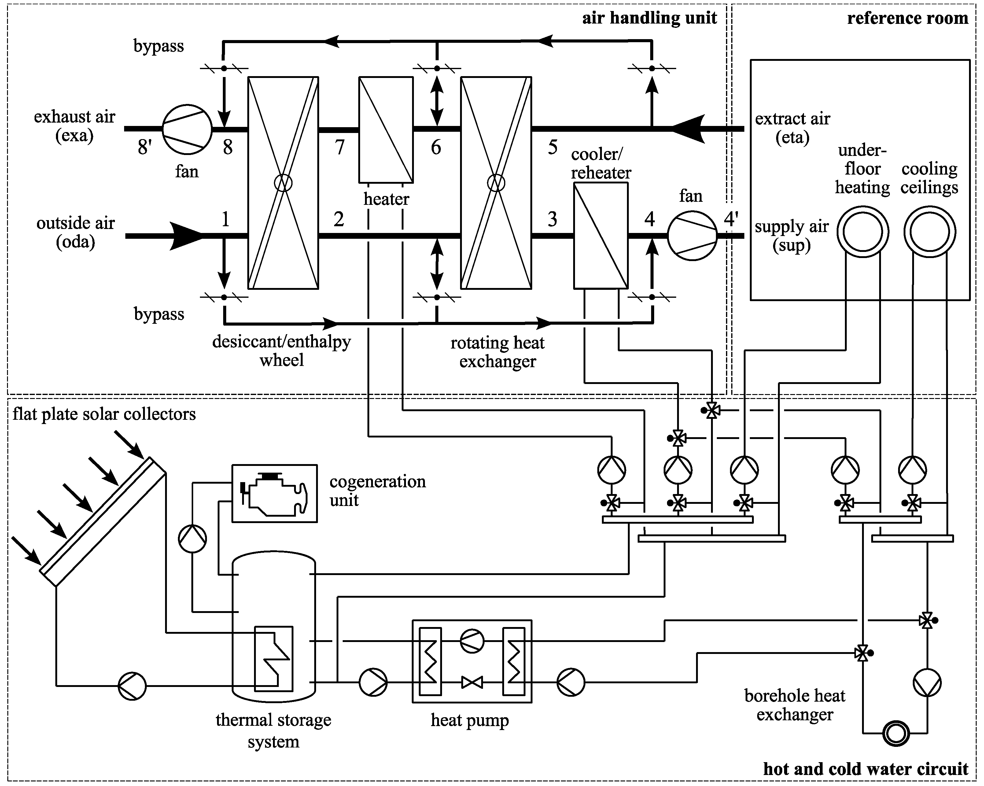
The following evaluation of system performance is based on measured data during the investigated periods. First, electrical power demand is considered. Electrical power demand of the entire system is in the range of 770–900 Wel during summer operation. The fans account for about 81–95% of this power demand, whereas the remaining part is divided equally between other auxiliary energies (e.g., drive of the wheels, circulation pumps). The electrical power demand of the GCHP has to be considered additionally during winter operation ( P GCHP = 887 1388   W el ). Indexing within the following equations is according to Figure 2.
To evaluate the air handling unit for the considered periods, electrical and thermal COP values are used. These performance indicators are defined according to [33]:
COP el , AHU , su = m ˙ sup ( h 1 h 4 ) P el , AHU COP el , AHU , wi = m ˙ sup ( h 4 h 1 ) P el , AHU
COP th , AHU , su = m ˙ sup ( h 1 h 4 ) Q ˙ th , AHU , su COP th , AHU , wi = m ˙ sup ( h 1 h 4 ) Q ˙ th , AHU , wi
Q ˙ th , AHU , su = m ˙ w , AH ( h w , in , AH h w , out , AH ) Q ˙ th , AHU , wi = m ˙ w , RH ( h w , in , RH h w , out , RH )
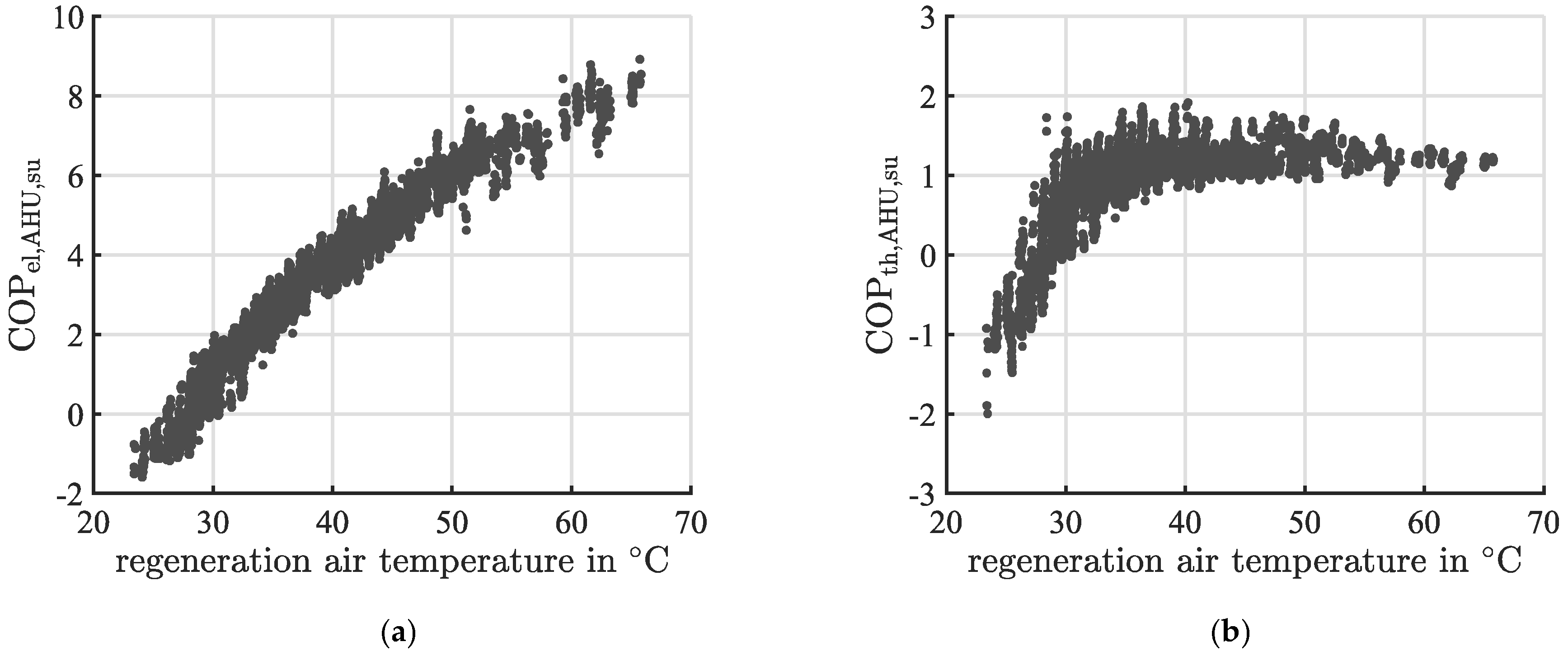
All figures shown in the following rely on steady-state operation conditions. Measured data were selected for steady state operation 15 minutes after the last changes made by system control. The electrical and thermal COP of the air handling unit during summer operation at dehumidification mode are shown in Figure 4 in dependence of regeneration air temperature. A strong dependence between COP el , AHU , su and regeneration air temperature is visible from the plot in Figure 4a. Due to the fact that the electrical energy demand of the AHU is nearly independent of the outside air conditions, COP el , AHU , su is increased with increasing regeneration air temperature. Increase in regeneration air temperature is a result of increasing water content and/or temperature of outside air within dehumidification mode. With respect to Figure 4b, desired supply air temperature cannot be maintained at high outside air temperature and water content, causing an increase in supply air enthalpy, respectively. This causes flattening of the curve for COP el , AHU , su with increasing regeneration air temperature. Due to its definition, negative values of COP el , AHU , su occur at low outside air temperatures when dehumidification of supply air is necessary whereas cooling is not required.
At values of regeneration air temperature below 35 °C, the increase of AHU thermal COP with increasing regeneration air temperature is much steeper compared to the slope of COP th , AHU , su at higher regeneration air temperature. This characteristic results from the mathematical definition of COP th , AHU , su as presented in Equation (2). Negative values of COP th , AHU , su occur at low regeneration air temperature when dehumidification is still necessary and reheating of supply air is required at the same time. For higher regeneration air temperatures above 35 °C, thermal COP keeps nearly constant at COP th , AHU , su 1 with decreasing fluctuations for increasing regeneration air temperature.
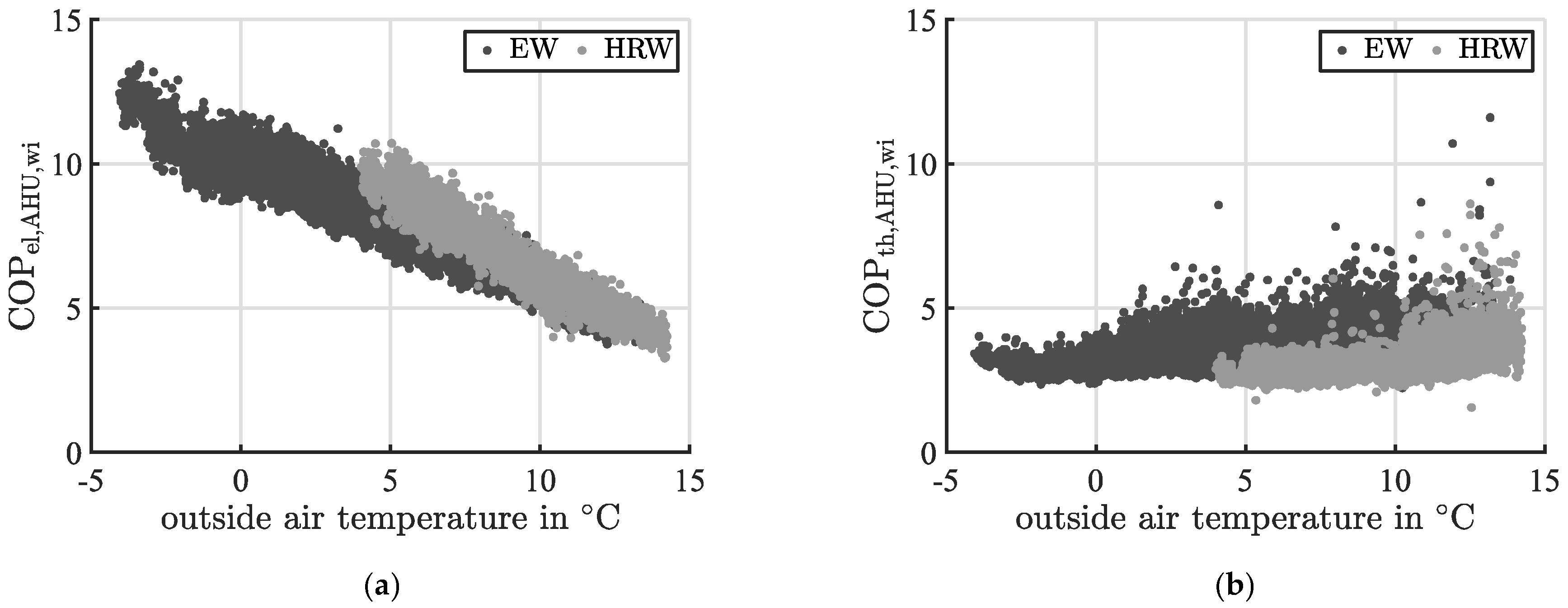
For the investigated heating period, performance indicators in form of COP el , AHU , wi and COP th , AHU , wi are shown in Figure 5. To evaluate the performance of the air handling unit during winter mode, the characteristics of COP el , AHU , wi and COP th , AHU , wi depending on outside air temperature are presented for EW mode and HRW mode.
As shown in Figure 5a, the electrical COP of the air handling unit is decreasing with nearly constant gradient for increasing outside air temperature in both operation modes. With respect to Equation (1), this is a result of decreasing nominator with increasing outside air temperature, whereas the denominator keeps constant in good approximation. Generally, water content of outside air is sufficient regarding indoor air comfort limits at higher outside air temperature level. Thus, HRW mode is just occurring at outside air temperatures above 4 °C. Due to similar electrical energy demand of the wheels as well as similar pressure drop across these components, the resulting gradients of COP el , AHU , wi are similar. The dependence of thermal COP on outside air temperature for the air handling unit during winter operation is shown in Figure 5b. In spite of increasing fluctuations with increasing outside air temperature, COP th , AHU , wi is independent of outside air temperature and not dropping below COP th , AHU , wi = 2 . This is a result of its definition, as presented in Equation (2), with similar characteristic of nominator and denominator for the underlying boundary conditions.
To further evaluate desiccant assisted dehumidification and enthalpy recovery in detail, mode-specific key figures have to be defined. In order to take the fact into account that the desiccant wheel is used for active dehumidification with a regeneration air heater, dehumidification efficiency is defined as follows:
DCOP = m ˙ sup ( x 1 x 4 ) r 0 Q ˙ th , AHU , su     ,
with Q ˙ th , AHU , su according to Equation (3) and is therefore equivalent to the definition of latent COP. An average dehumidification efficiency of DCOP ¯ = 1.15 was achieved for the considered cooling period. This result indicates that more latent thermal power was absorbed within the desiccant wheel compared to the required thermal power to run the regeneration air heater. In general, regenerative heat exchange within the air handling unit improves dehumidification efficiency by preheating extract air for regenerating the desiccant wheel. Due to the fact that the wheel is used for passive enthalpy recovery during winter, moisture recovery efficiency is expressed by:
Ψ = x 2 x 1   x 7 x 1   .
An average moisture recovery efficiency of Ψ ¯ = 0.75 was achieved for the enthalpy wheel during the investigated winter period. Thus, an increase of 1.1   g w   kg air 1 was achieved for sup humidity ratio on average. Maximum values of moisture recovery were close to 2.3   g w   kg air 1 for the underlying boundary conditions.

3.2. Performance Evaluation of the Geothermal System

Performance evaluation of the overall geothermal system is structured into three parts. First, soil temperature and soil energy balance are considered. Afterwards, energy transfer at the BHE is investigated and finally, GCHP performance is evaluated.
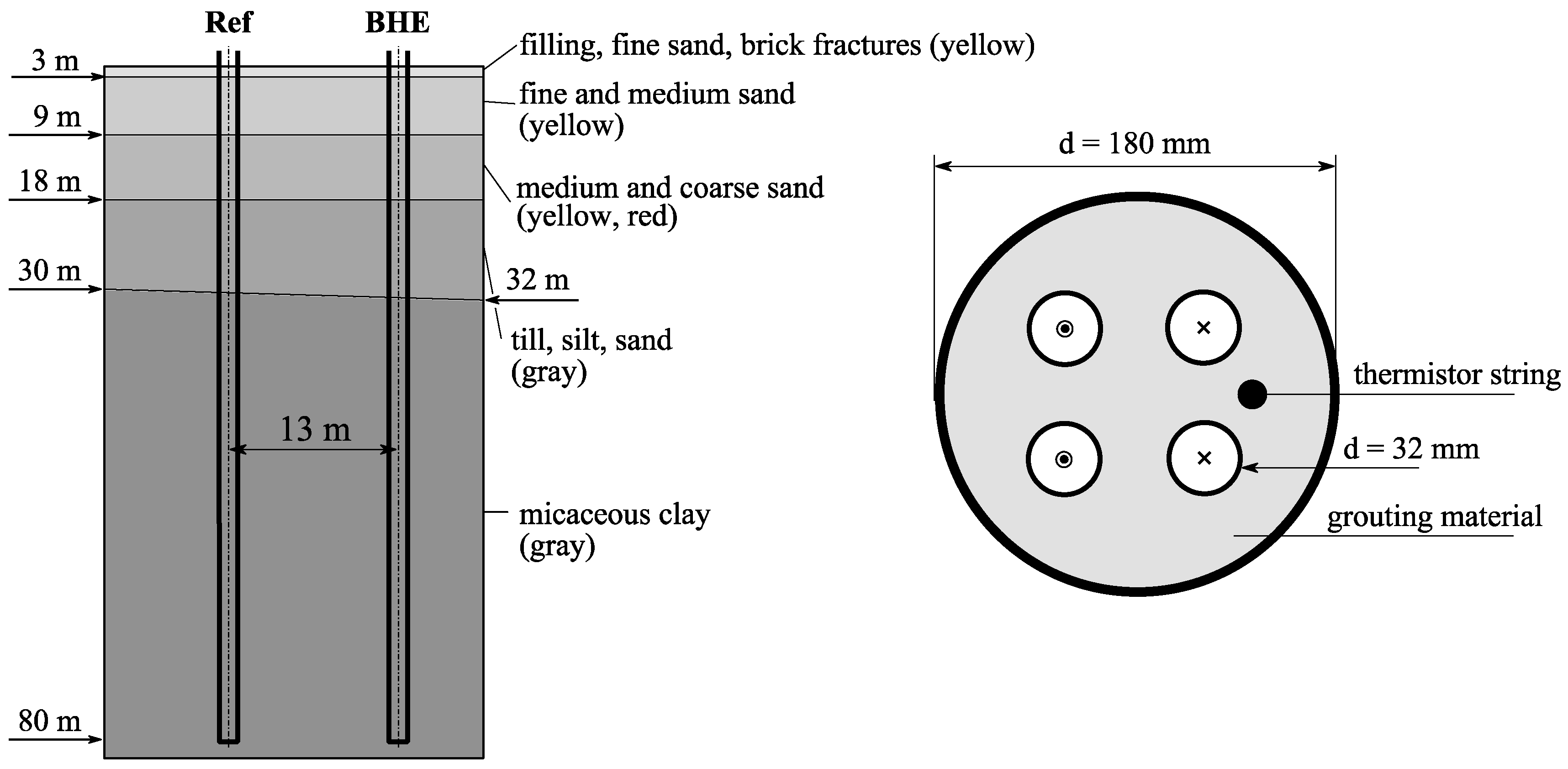
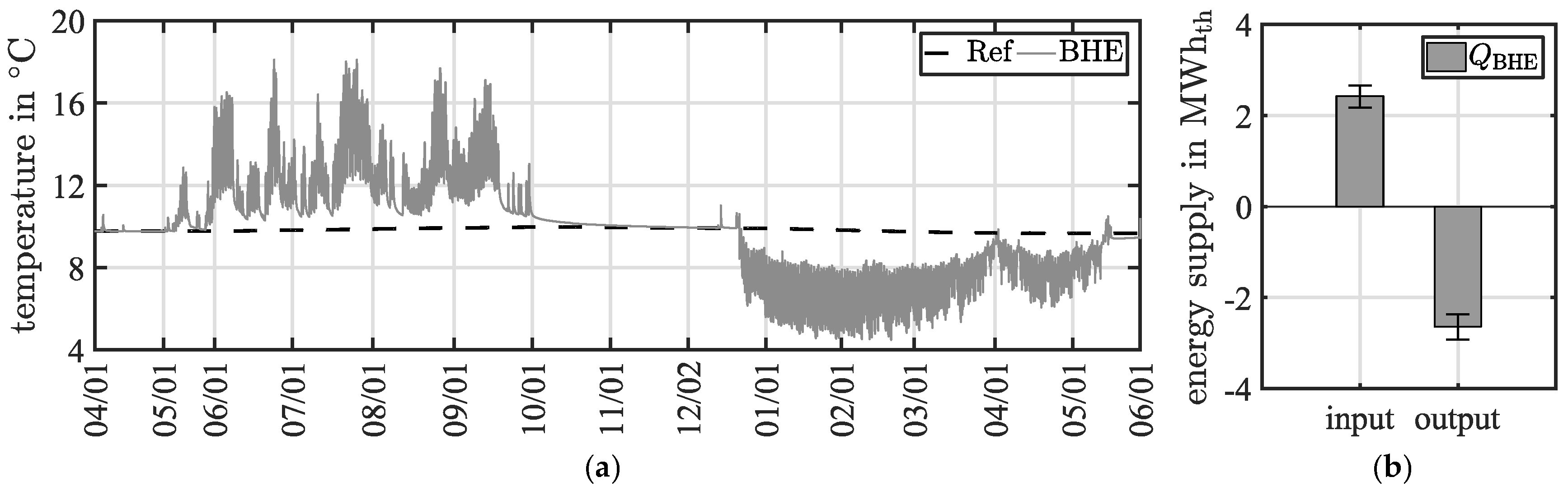
Temperature profiles of BHE and the considered reference BHE are shown in Figure 6a for the period of around one year including summer and winter operation. The soil temperature 15 m below ground surface was found to be independent of seasonal related temperature fluctuations during previous investigations. Thus, the plots result from temperature averaging below 15 m for both, BHE and reference BHE. Depending on the season and operation mode of the air conditioning system, the the soil around the BHE is significantly influenced with dynamic temperature profile during cooling and heating mode. Cooling peak loads occurring in summer operation lead to maximum soil temperatures above 18 °C. This temperature level is crucial with respect to keep the desired indoor air temperature level below 25.5 °C. Regardless of such peak loads that only occurred at a few days of the considered cooling period, the soil temperature was kept within a sufficient temperature range in terms of cooling purposes. During winter operation, the soil temperature is less fluctuating compared to its use as heat sink. The lowest soil temperature was 4.5 °C that occurred during the coldest period in the beginning of February. Using the soil for heating, the soil temperature decrease is crucial to operate the GCHP system efficiently. This dependence is further analyzed later on in this subsection. Average temperature level of the undisturbed soil at the reference BHE was at 9.8 °C. Occurring temperature fluctuations were within the corresponding uncertainty of temperature measurement.
Balancing input and output of thermal energy during summer and winter operation and natural regeneration of the soil, an equalized energy balance of the soil was achieved. Input and output of thermal energy at the BHE are balanced with a remaining annual difference of 0.22   MWh th , 9% respectively, as shown in Figure 6b. This difference is within measurement uncertainty of the corresponding energy values. With respect to these results an efficient long-term operation of the geothermal system can be predicted. Nevertheless, an ongoing long-term monitoring of the geothermal system is essential, especially when large scale geothermal systems with several BHE influencing each other are considered.
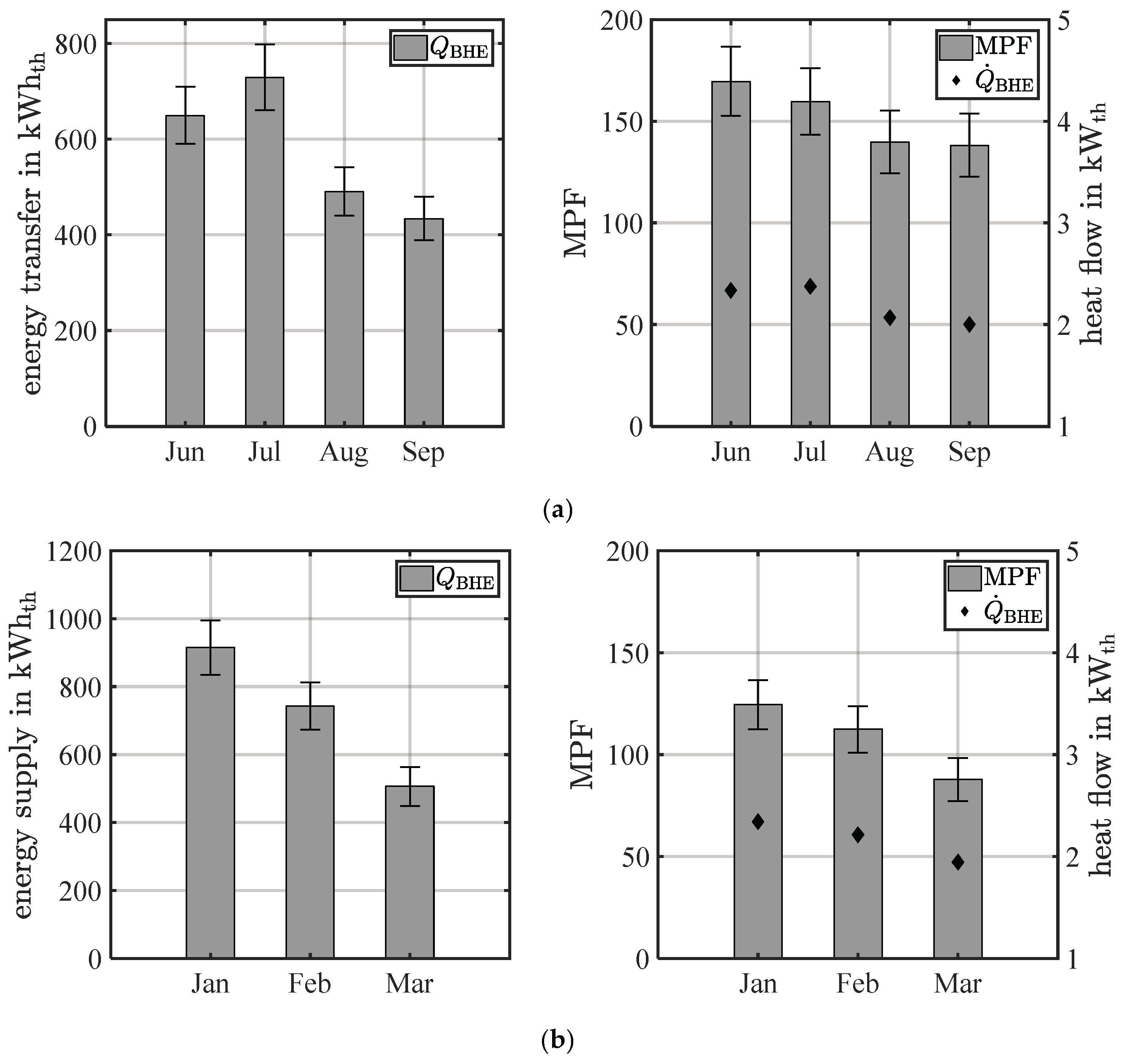
In terms of further investigating energetic performance of the geothermal system, month and period specific performance indicators are presented in Figure 7. For both periods the amount of energy ( Q BHE ) and heat flow ( Q ˙ BHE ) transferred at the BHE as well as resulting performance values are shown. Key figures as defined in [33] are used to evaluate BHE performance. With respect to the considered periods, Monthly Performance Factor (MPF) and Seasonal Performance Factor (SPF) are used as presented in Equation (6):
MPF = m   | Q ˙ BHE |   d τ m   P PU   d τ SPF = p   | Q ˙ BHE |   d τ p   P PU   d τ
The denominator includes the electrical energy demand of the BHE circulation pump. Decreasing MPF values occurred over each period as a result of changing temperature level of the soil surrounding the BHE by charging or discharging energy in form of heat. The amount of thermal energy, heat flow and resulting MPF show the same relationship for both periods with one exception. Even though the month of July shows the largest amount of thermal energy transferred to the soil, the highest MPF was achieved in June with MPF su , max = 170 ± 17 , see Figure 7a. This was primarily caused by lower temperature increase of the soil during June. Evaluating the entire cooling period, a seasonal performance of SPF su = 153 ± 15 was achieved, indicating a high efficiency of the geothermal heat sink. The same holds true for the winter period with a resulting seasonal performance of SPF wi = 110 ± 11 , even though the value is around 28% lower compared to summer mode. The reason for this difference is related to the required volume flow of heat transfer medium to supply the evaporator of the heat pump that is generally higher than volume flows of heat transfer medium for natural cooling in summer.
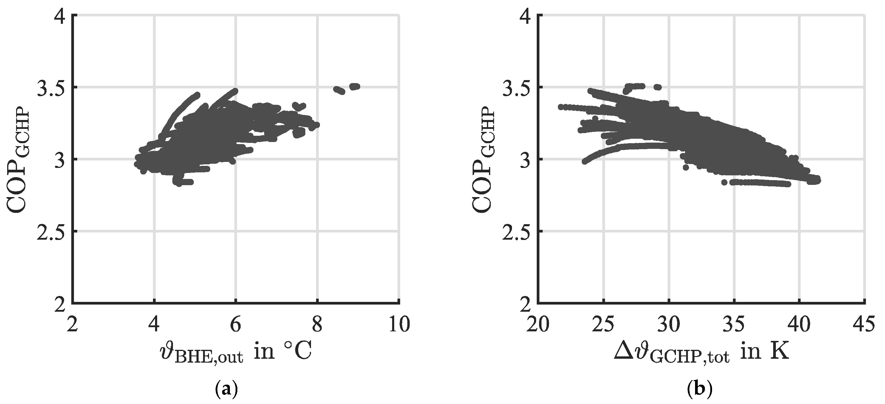
To further analyze GCHP performance, its electrical COP, see Equation (7), is investigated in more detail in terms of available and required temperature levels as shown in Figure 8:
COP GCHP = | Q ˙ h | P GCHP + P AUX
BHE outlet temperatures were mostly pooled in the range of ϑ BHE , out = 3.8 8   ° C during steady state GCHP operation with a range of COP GCHP = 2.9 3.5 , as shown in Figure 8a. A trend of increasing COP GCHP with increasing BHE outlet temperature is visible. This is an effect of lower required temperature lift within GCHP process that comes along with reduced power level required to run the compressor. Taking the required temperature lift as a further indicator of GCHP load into account, a slight dependence on GCHP performance can be deduced from Figure 8b. The temperature lift Δ ϑ GCHP , tot is defined as temperature difference between condenser outlet and evaporator inlet. Values above Δ ϑ GCHP , tot = 32   K that were required to supply UHS caused GCHP performance lower than 3 with decreasing trend curve. Taking the overall heating period into account, SPF of the GCHP system can be determined equivalent to Equation (6) by integrating thermal and electrical powers from Equation (7):
SPF GCHP = p   | Q ˙ h |   d τ p   ( P GCHP + P AUX )   d τ
For the considered heating period SPF GCHP = 3 was achieved. Compared to GCHP systems state of the art with SPF GCHP = 4.0 4.5 , performance of the investigated system relying on a reciprocating compressor shows potential for improvement. Nevertheless, this system is robust against fluctuating temperature levels.

3.3. Evaluation of Thermal Comfort

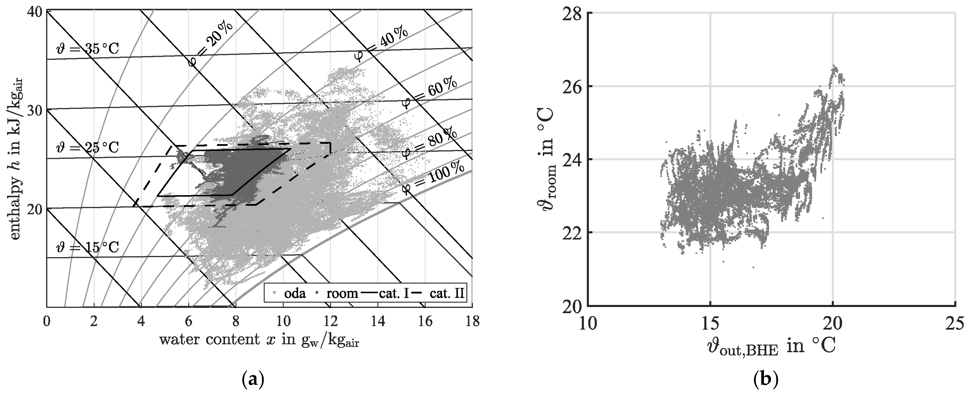
The quality of indoor air conditions is a result of the performance and operation strategy of the overall system. To provide an overview of comfort conditions for the investigated periods, outside and room air conditions during system operation are shown in Figure 9a and Figure 10a with simplified comfort areas according to DIN EN 15251 [38]. Comfort areas of category I and II are defined to ensure less than 6% (cat. I) and 10% (cat. II) of occupants being dissatisfied with the present indoor air conditions. In order to exclude start-up effects, the first hour of system operation is not considered.
For the investigated cooling period, indoor air conditions according to cat. I were maintained for 55% and cat. II was maintained for over 96% of operation time, respectively. The reasons for the remaining violations were different for cat. I and cat. II. Cat. I was violated primarily due to too high indoor air humidity, whereas too high indoor air temperatures caused violations of cat. II.
In order to further analyze the reasons for overheating, Figure 9b shows the dependence of room air temperature ϑ room on water outlet temperature ϑ out , BHE of the BHE. Outlet temperature of the BHE is similar to the cooling ceilings’ inlet temperature. With good approximation, a linear increase of indoor air temperature with increasing BHE outlet temperature above 18 °C is visible. Maximum room air temperatures were right above 26 °C at maximum BHE outlet temperature of ϑ out , BHE , max = 20.5   ° C . This is an effect of peak loads that could not be covered by the geothermal heat sink due to its limited capacity and little controllable thermal power output.
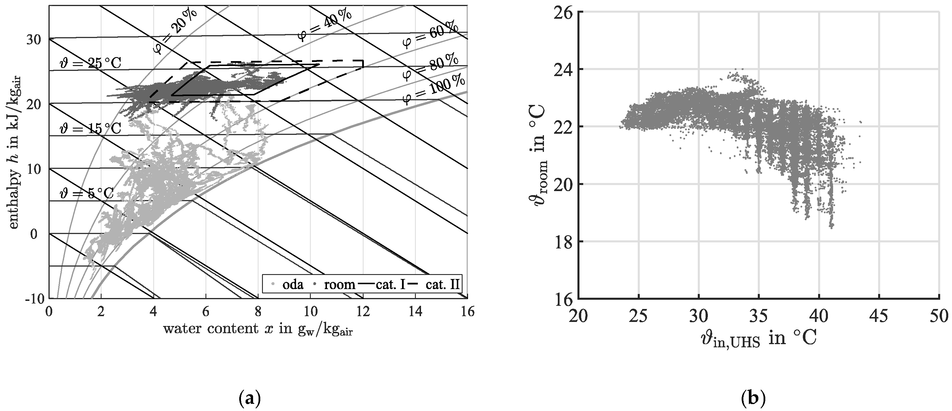
According to the German Meteorological Service, the investigated heating period can be classified as moderate. The average oda temperature in January was 1.67 °C at an average water content of 3.3   g w   · kg air 1 . The following months were characterized by higher oda temperature and water content. As shown in Figure 10a, nearly 100% of oda conditions were outside comfort area according to cat. I and II. Days with oda conditions within the desired comfort area just occurred during springtime period at the end of March.
Around 67% of indoor air conditions satisfied the requirements according to cat. I. Cat. II was maintained for 75% of system operation time, respectively. The remaining violations were primarily caused by too low indoor air temperature. As a result of the control strategy for the underfloor heating system (UHS) and insufficient internal loads, 85% of indoor air temperatures below the desired temperature level occurred during the first four hours of daily system operation. A similar characteristic applied to indoor air water content. The level of sup and indoor air water content is mainly depending on oda water content if constant internal latent loads are provided. Thus, 75% of indoor air conditions characterized by insufficient level of water content occurred at oda water contents below 2.5   g w ·   kg air 1 . Without humidification of supply air, over 60% of room air conditions would have been outside of cat. I. Over-humidification of room air did not occur during the entire heating period.
Figure 10b shows the dependence of indoor air temperature ϑ room on UHS inlet temperature ϑ in , UHS . A trend of increasing fluctuation of indoor air temperature with increasing UHS inlet temperature is noticable, especially for ϑ in , UHS > 32   ° C . This is an effect of insufficient thermal power supply during the first hours after system start-up at low oda temperatures. Taking this initial situation, improvement of the control strategy for the UHS is required in terms of limiting periods at insufficient thermal comfort. The GCHP system was not operated between 10 pm and 7 am, while underfloor heating was provided 24 hours a day. Providing and storing sufficient amounts of thermal energy can be achieved by operating the GCHP system additionally during night. Resulting shorter regeneration periods of the soil have to be considered for the proposed operation strategy focusing on increase in thermal comfort.
Table 3 lists the relative shares of operation modes for both periods for the given outside air conditions and the implemented control strategies. The significant amount of DW or EW mode represents the importance of desiccant assisted air conditioning to provide a high level of indoor air conditions throughout the year.

3.4. System Comparison

The investigated system is compared to different reference systems in order to further evaluate its energetic performance. These reference systems are designed as mathematical simulation models relying on measured data of the investigated system (DW-GEO). Thus, the thermodynamic processes of the considered reference systems were modeled relying on simplified thermodynamic relations and required assumptions. Measurement data of the investigated system were used whenever similar air states are expected for the reference systems in comparison to DW-GEO. In order to ensure a fair system comparison, oda and sup conditions as well as sup mass flow rate and room air conditions were assumed to be equal with one exception that is explained later on. Air dehumidification as well as air humidification within the reference systems are considered according to the equivalent operation modes of the investigated system. In each operation mode, summer and winter, two different reference systems were designed. During summer operation, reference systems relying on an electrical powered vapor compression chiller are considered. Humidifying processes with adiabatic or isothermal air humidification are considered for the reference systems regarding winter operation. The individual characteristics of each reference system are summarized in Table 4.
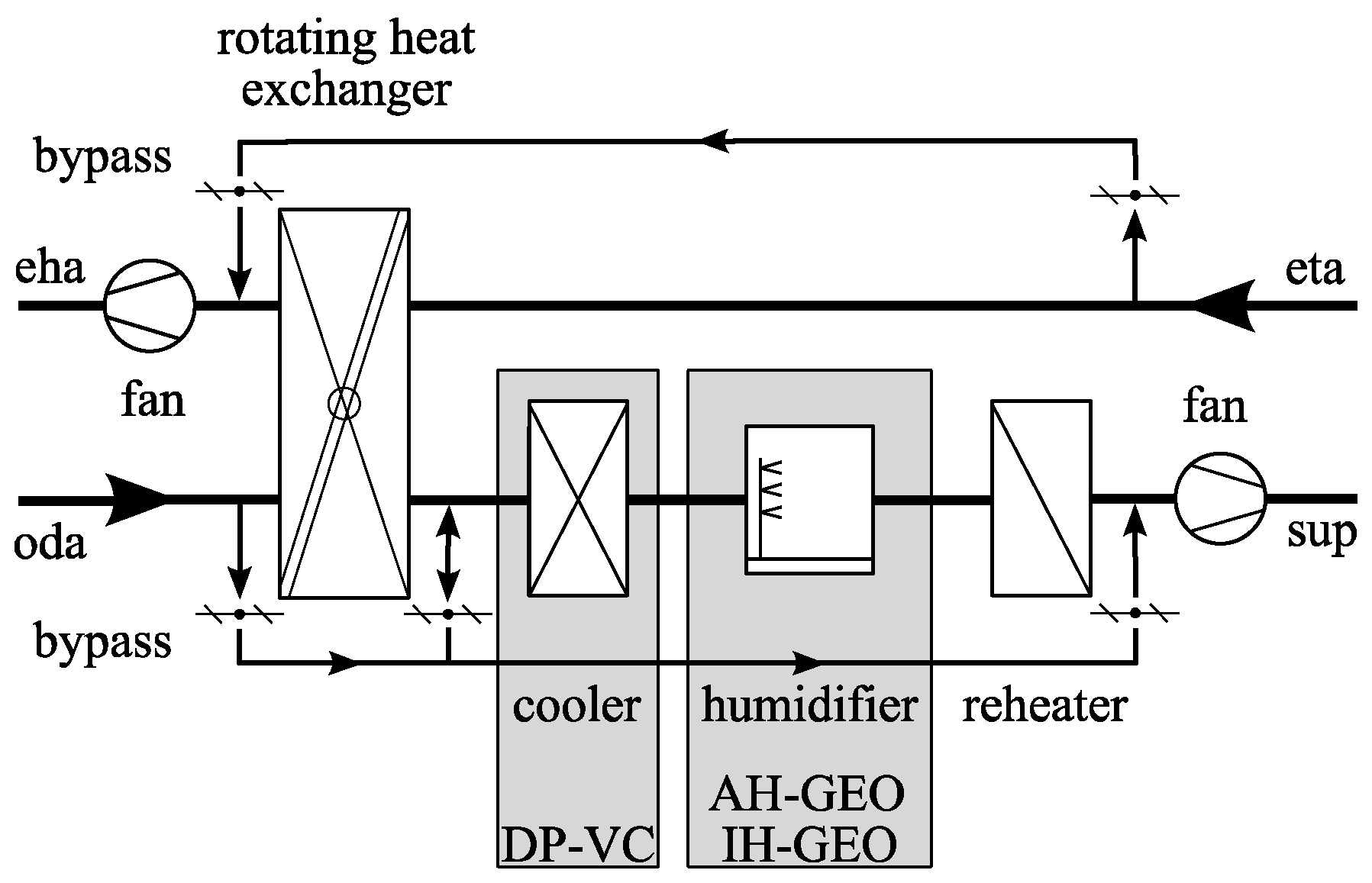
Supply air temperature of the conventional reference system (DP-VC) was set to 18 °C in order to ensure a fair system comparison. Changes in thermal load discharge by air and cooling ceilings was considered. The second reference system for the cooling period is a hybrid air conditioning system (DW-VC); the BHE is replaced by a vapor compression chiller, while the rest of the investigated system remains unchanged. The specific layout of corresponding air handling units for the reference systems DP-VC and AH-GEO/IH-GEO is shown in Figure 11. Highlighted components are specific for the designated reference systems, whereas the rest of the air handling unit remains the same for these systems.
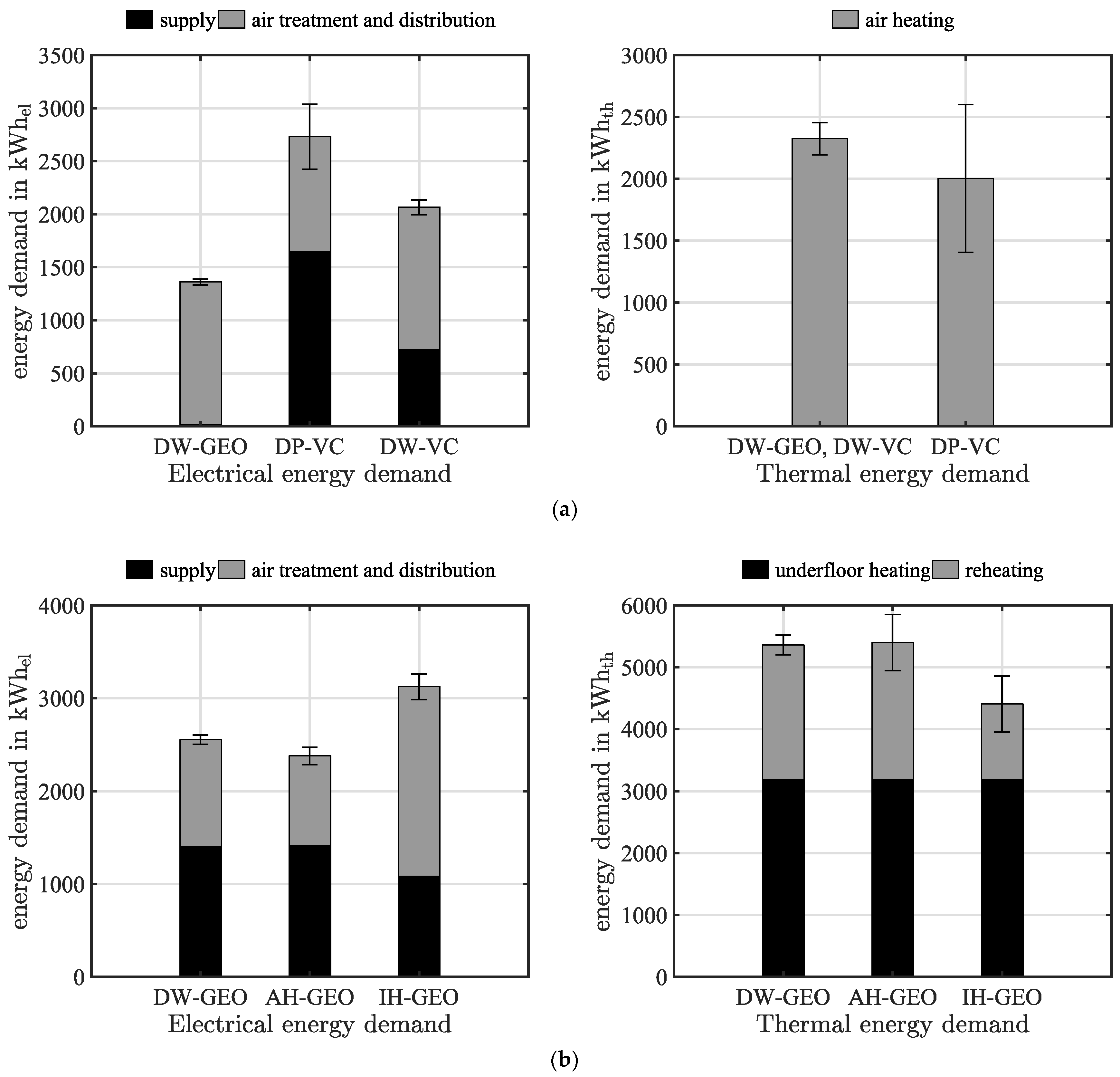
Figure 12 shows the results of the system comparison for the considered periods. Legend entry “supply” includes electricity demands of the compression chiller (DP-VC, DW-VC) or rather the BHE circulation pump (DW-GEO) during summer operation, see Figure 12a. During winter operation, shown in Figure 12b, it includes the heat pump and corresponding auxiliary energies, respectively. Electricity demand of the AHU and circulation pumps of the hydraulic circuits are summarized to category “air treatment and distribution” for both periods. Electrical and thermal energy demands are related to the entire periods under consideration. All values of electrical and thermal energy demands shown in Figure 12 are also listed in Table 5 for more transparency.
As shown in Figure 12a, the investigated system boasts significant reductions in electrical energy demand compared to the reference systems during summer operation. The savings sum up to 50% compared to the conventional system (DP-VC) and 34% compared to the hybrid system (DW-VC). These savings were primarily caused by the chiller unit (black column) that required 61% of the total electrical energy demand for the system DP-VC, whereas just 1% of the system DW-GEO was required for the BHE circulation pump. Due to the fact that only sensible cooling is required for the chiller unit of the hybrid system, its electricity demand was reduced by more than 50% compared to the conventional system. The overall AHU electricity demand of the system DP-VC was lower compared to the desiccant assisted systems (DW-GEO, DW-VC), because pressure drop across the desiccant wheel was saved for this system. Considering thermal energy demands, the conventional system shows the lowest thermal energy demand for reheating supply air. The required regeneration process within the desiccant assisted systems caused an increase of thermal energy demand by a factor of 1.2 compared to the system DP-VC. In total, the differences in thermal energy demand were not significantly high caused by the moderate summer period with a certain amount of oda conditions that required reheating but no or only moderate dehumidification. Nevertheless, the increased thermal energy demand of desiccant assisted air conditioning requires a convenient and low-cost heat source regarding primary energy demand of heat supply.
During winter operation, as shown in Figure 12b, the benefits of the investigated system (DW-GEO) are not as obvious as in summer mode. Thus, electrical and thermal energy demands have to be analyzed carefully. For the reference system with electric isothermal air humidification (IH-GEO) electricity demand for air treatment and distribution was increased by a factor of 1.8 compared to DW-GEO. This was significantly induced by the electrical steam humidifier that accounts for nearly 50% of the corresponding gray column. The corresponding electricity demand for AH-GEO was reduced by 16% compared to DW-GEO for the following reasons. First, the additional electricity demand for the impeller humidifier is low and second, the pressure drop associated with the enthalpy wheel is saved. This applies for IH-GEO, respectively. Due to the reasons mentioned above, the electricity demand to operate the GCHP system is almost equal for the systems DW-GEO and AH-GEO. For the reason of high temperature steam used to humidify supply air within the system IH-GEO, required GCHP power was lower in terms of adjusting sup stream to the desired sup temperature. In total, the electricity demand of DW-GEO was reduced by 18% compared to IH-GEO and it was increased by 7% compared to AH-GEO.
Thermal energy demand required for underfloor heating is assumed to be equal for the three systems. Thermal energy required for reheating sup to the desired sup temperature was about 44% higher for the DW-GEO and AH-GEO systems compared to the system with isothermal air humidification due to substitution of thermal energy by electricity as described above. Even though the differences are quite small, considering both, electrical and thermal energy demands, system comparison shows lowest total energy demand for AH-GEO. This results from the slight advantage in electricity demand of AH-GEO against the investigated system. Thus, energetic benefits of the investigated system were limited for the considered heating period. It is expected that increased benefits will be achieved for winter terms with lower oda temperature and water content. Nevertheless, moisture recovery using an enthalpy wheel is beneficial against the reference technologies from a hygienic point of view, especially for the use of LiCl desiccant material.
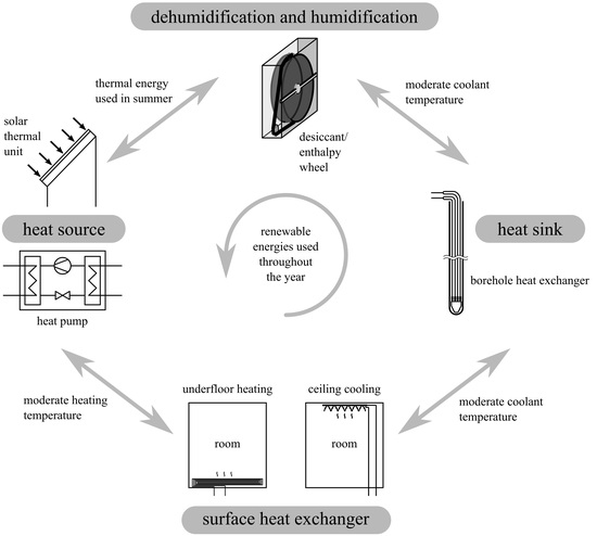
Summarizing, taking summer and winter operation into account, the investigated system boasts significant reductions in electricity demand, resulting from the electricity savings during summer operation. Additional thermal energy demand required for regeneration of the desiccant wheel is not significantly higher at the same time. The required temperature level up to 70 °C can commonly be easily provided by solar thermal energy. Nevertheless, providing thermal energy as favorable as possible is crucial considering the economic efficiency of the system. Another advantage of the investigated system is the reduced amount of mode specific equipment. Subsystems like the desiccant wheel and the geothermal system of the investigated system are used throughout the year, whereas this holds not true for the chiller and the air humidifier of the reference systems.

4. Conclusions

In this study experimental investigations of an air conditioning system during summer and winter mode relying on desiccant assisted dehumidification and enthalpy recovery and a geothermal system used for cooling and heating are presented. The investigated system is able to fulfill the requirements regarding comfortable indoor air conditions during the investigated periods. A desiccant wheel based on LiCl is used for air dehumidification and remoistening, achieving an average dehumidification efficiency of 1.15 and a moisture recovery efficiency of 0.75. Compared to reference processes the investigated system is beneficial during summer mode. Savings in electrical energy demand of up to 50% are achieved compared to a conventional air conditioning process. In contrast, a reference system relying on adiabatic air humidification shows slight benefits for the investigated heating period. Nevertheless, desiccant assisted humidification is advantageous compared to other humidification processes regarding hygienic aspects. If full year operation of an air conditioning system requires air dehumidification during summer it is essential to make use of the pre-existing desiccant material for remoistening of process air during winter. Additionally, the amount of mode specific equipment is reduced for desiccant assisted air conditioning with respect to full year operation. Required temperature levels of the working fluids enable the energetic use of a geothermal system for cooling and heating applications. The thermal energy balance of the soil is equalized throughout full year operation, enabling the soil to be used as heat source and heat sink for long-term periods. Thus, the amount of renewable energy sources is increased significantly to ensure environmental friendly air conditioning.
The research project includes detailed investigation of thermal comfort and economic assessment that are not presented in this study. For future research work, the most beneficial system configuration has to be found with respect to full year operation including transition periods as well. Additionally, other desiccant materials will be investigated. Furthermore, a system simulation model is created in order to carry out dynamic system simulations to analyze applicability of the investigated system for different locations during full year operation as well as different system setups.

Author Contributions

Conceptualization, P.N., F.R. and A.S.; methodology, P.N. and A.S.; software, P.N. and A.S.; validation, P.N., F.R. and A.S.; formal analysis, P.N., F.R. and A.S.; investigation, P.N. and A.S.; writing—original draft preparation, P.N.; writing—review and editing, P.N.; visualization, P.N.; supervision, P.N., F.R. and A.S.; project administration, F.R.; G.S.; funding acquisition, G.S. All authors have read and approved the final manuscript.

Funding

This work is being conducted in the frame of a project funded by the Federal Ministry for Economic Affairs and Energy (www.bmwi.de), cf. project funding reference number 03ET1421A.

Conflicts of Interest

The authors declare no conflict of interest.

Nomenclature

Latin symbols
Aarea, m2
cpspecific heat capacity, J·kg−1·K−1
COPcoefficient of performance, dimensionless value
ddiameter, m
DCOPdehumidification efficiency, dimensionless value
hspecific enthalpy, J·kg−1
m ˙ mass flow, kg·s−1
MPFmonthly performance factor, dimensionless value
Pelectrical power, W
Q thermal energy, J
Q ˙ thermal power, W
r0specific evaporation enthalpy, J·kg−1
SPFseasonal performance factor, dimensionless value
V ˙ volume flow, m3·s−1
Welectrical energy, J
xwater content, g w   k g a i r 1
Greek symbols
ϑ temperature, °C
λ thermal conductivity, W m 1 K 1
τ time, s
φ relative humidity, %   rh
Φ heat recovery efficiency, dimensionless value
Ψ moisture recovery efficiency, dimensionless value
Dimensionless values
difference
[ ¯ ] averaged quantity, dimensionless value
Subscripts and Abbreviations
AHair heater
AH-GEOAdiabatic Humidification and GEOthermal system”, reference system with adiabatic humidification and heat pump (winter)
AHUair handling unit
AUXauxiliary energies
BHEborehole heat exchanger
CHPcombined heat and power generation
DP-VCDew Point and Vapor Compression chiller”, reference system with vapor compression chiller and dehumidification by cooling below dew point temperature (summer)
DWdesiccant wheel
DW-GEODesiccant Wheel and GEOthermal system”, investigated system
DW-VCDesiccant Wheel and Vapor Compression chiller”, reference system with vapor compression chiller and desiccant assisted dehumidification (summer)
elelectrical
etaextract air
exaexhaust air
EWenthalpy wheel
GCHPground-coupled heat pump
hheating
HRWheat recovery wheel
HVACheating, ventilation and air conditioning
IH-GEOIsothermal Humidification and GEOthermal system”, reference system with isothermal humidification and heat pump (winter)
ininlet
mmonth
maxmaximum
minminimum
nomnominal
odaoutside air
outoutlet
pperiod
PUcirculation pump
Refreference
RHreheater
setset point
STUsolar thermal unit
susummer
supsupply air
ththermal
UHSunderfloor heating system
wwater
wiwinter

References

  1. Davis, L.W.; Gertler, P.J. Contribution of air conditioning adoption to future energy use under global warming. Proc. Natl. Acad. Sci. USA 2015, 112, 5962–5967. [Google Scholar] [CrossRef] [PubMed] [Green Version]
  2. International Energy Agency. The Future of Cooling—Opportunities for Energy-Efficient Air Conditioning. Available online: https://webstore.iea.org/the-future-of-cooling (accessed on 20 March 2019).
  3. International Energy Agency. Energy Technology Perspectives 2010—Scenarios & Strategies to 2050. Available online: https://webstore.iea.org/energy-technology-perspectives-2010 (accessed on 20 March 2019).
  4. Isaac, M.; Van Vuuren, D.P. Modeling global residential sector energy demand for heating and air conditioning in the context of climate change. Energy Policy 2009, 37, 507–521. [Google Scholar] [CrossRef]
  5. Enteria, N.; Mizutani, K. The role of the thermally activated desiccant cooling technologies in the issue of energy and environment. Renew. Sustain. Energy Rev. 2011, 15, 2095–2122. [Google Scholar] [CrossRef]
  6. Vakiloroaya, V.; Samali, B.; Fakhar, A.; Pishghadam, K. A review of different strategies for HVAC energy saving. Energy Convers. Manag. 2014, 77, 738–754. [Google Scholar] [CrossRef]
  7. Shehadi, M. Review on humidity control technologies in buildings. J. Build. Eng. 2018, 19, 539–551. [Google Scholar] [CrossRef]
  8. Jani, D.B.; Mishra, M.; Sahoo, P.K. Solid desiccant air conditioning—A state of the art review. Renew. Sustain. Energy Rev. 2016, 60, 1451–1469. [Google Scholar] [CrossRef]
  9. Kojok, F.; Fardoun, F.; Younes, R.; Outbib, R. Hybrid cooling systems: A review and an optimized selection scheme. Renew. Sustain. Energy Rev. 2016, 65, 57–80. [Google Scholar] [CrossRef]
  10. Ge, T.S.; Dai, Y.J.; Wang, R.Z. Review on solar powered rotary desiccant wheel cooling system. Renew. Sustain. Energy Rev. 2014, 39, 476–497. [Google Scholar] [CrossRef]
  11. La, D.; Dai, Y.J.; Li, Y.; Wang, R.Z.; Ge, T.S. Technical development of rotary desiccant dehumidification and air conditioning: A review. Renew. Sustain. Energy Rev. 2010, 14, 130–147. [Google Scholar] [CrossRef]
  12. Al-Alili, A.; Hwang, Y.; Radermacher, R. Performance of a desiccant wheel cycle utilizing new zeolite material: Experimental investigation. Energy 2015, 81, 137–145. [Google Scholar] [CrossRef]
  13. Eicker, U.; Schürger, U.; Köhler, M.; Ge, T.; Dai, Y.; Li, H.; Wang, R. Experimental investigations on desiccant wheels. Appl. Therm. Eng. 2012, 42, 71–80. [Google Scholar] [CrossRef]
  14. Ruivo, C.R.; Angrisani, G.; Minichiello, F. Influence of the rotational speed on the effectiveness parameters of a desiccant wheel: An assessment using experimental data and manufacturer software. Renew. Energy 2015, 76, 484–493. [Google Scholar] [CrossRef]
  15. Angrisani, G.; Minichiello, F.; Sasso, M. Improvements of an unconventional desiccant air conditioning system based on experimental investigations. Energy Convers. Manag. 2016, 112, 423–434. [Google Scholar] [CrossRef] [Green Version]
  16. Chen, C.-H.; Hsu, C.-Y.; Chen, C.-C.; Chiang, Y.-C.; Chen, S.-L. Silica gel/polymer composite desiccant wheel combined with heat pump for air-conditioning systems. Energy 2016, 94, 87–99. [Google Scholar] [CrossRef]
  17. Angrisani, G.; Roselli, C.; Sasso, M. Experimental assessment of the energy performance of a hybrid desiccant cooling system and comparison with other air-conditioning technologies. Appl. Energy 2015, 138, 533–545. [Google Scholar] [CrossRef]
  18. Al-Alili, A.; Hwang, Y.; Radermacher, R. A hybrid solar air conditioner: Experimental investigation. Int. J. Refrig. 2014, 39, 117–124. [Google Scholar] [CrossRef]
  19. Fong, K.F.; Lee, C.K.; Chow, T.T.; Fong, A.M.L. Investigation on solar hybrid desiccant cooling system for commercial premises with high latent cooling load in subtropical Hong Kong. Appl. Therm. Eng. 2011, 31, 3393–3401. [Google Scholar] [CrossRef]
  20. Ghali, K. Energy savings potential of a hybrid desiccant dehumidification air conditioning system in Beirut. Energy Convers. Manag. 2008, 49, 3387–3390. [Google Scholar] [CrossRef]
  21. Mazzei, P.; Minichiello, F.; Palma, D. Desiccant HVAC systems for commercial buildings. Appl. Therm. Eng. 2002, 22, 545–560. [Google Scholar] [CrossRef]
  22. El-Agouz, S.A.; Kabeel, A.E. Performance of air conditioning system with geothermal energy under different climatic conditions. Energy Convers. Manag. 2014, 88, 464–475. [Google Scholar] [CrossRef]
  23. Wrobel, J.; Walter, P.S.; Schmitz, G. Performance of a solar assisted air conditioning system at different locations. Sol. Energy 2013, 92, 69–83. [Google Scholar] [CrossRef]
  24. Casas, W.; Schmitz, G. Experiences with a gas driven, desiccant assisted air conditioning system with geothermal energy for an office building. Energy Build. 2005, 37, 493–501. [Google Scholar] [CrossRef]
  25. Angrisani, J.; Diglio, G.; Sasso, M.; Calise, F.; Dentice d’Accadia, M. Design of novel geothermal heating and cooling system: Energy and economic analysis. Energy Convers. Manag. 2016, 108, 144–159. [Google Scholar] [CrossRef]
  26. Beccali, M.; Finocchiaro, P.; Nocke, B. Energy performance of a demo solar desiccant cooling system with heat recovery for the regeneration of the adsorption material. Renew. Energy 2012, 44, 40–52. [Google Scholar] [CrossRef]
  27. De Antonellis, S.; Intini, M.; Joppolo, C.M.; Molinaroli, L.; Romano, F. Desiccant wheels for air humidification: An experimental and numerical analysis. Energy Convers. Manag. 2015, 106, 355–364. [Google Scholar] [CrossRef]
  28. Kawamoto, K.; Cho, W.; Kohno, H.; Koganei, M.; Ooka, R.; Kato, S. Field Study on Humidification Performance of a Desiccant Air-Conditioning System Combined with a Heat Pump. Energies 2016, 9, 89. [Google Scholar] [CrossRef]
  29. La, D.; Dai, Y.; Li, H.; Li, Y.; Kiplagat, J.K.; Wang, R. Experimental investigation and theoretical analysis of solar heating and humidification system with desiccant rotor. Energy Build. 2011, 43, 1113–1122. [Google Scholar] [CrossRef]
  30. Preisler, A.; Brychta, M. High potential of full year operation with solar driven desiccant evaporative cooling systems. Energy Procedia 2012, 30, 668–675. [Google Scholar] [CrossRef]
  31. Zhang, L.Z.; Niu, J.L. Performance comparisons of desiccant wheels for air dehumidification and enthalpy recovery. Appl. Therm. Eng. 2002, 22, 1347–1367. [Google Scholar] [CrossRef]
  32. Strindehag, O.; Josefsson, I.; Henningson, E. Emission of bacteria from air humidifiers. Environ. Int. 1991, 17, 235–241. [Google Scholar] [CrossRef]
  33. Speerforck, A.; Schmitz, G. Experimental investigation of a ground-coupled desiccant assisted air conditioning system. Appl. Energy 2016, 181, 575–585. [Google Scholar] [CrossRef] [Green Version]
  34. Speerforck, A. Investigation of a Desiccant Assisted Geothermal Air Conditioning System, 1st ed.; Verlag Dr. Hut: Munich, Germany, 2019. [Google Scholar]
  35. Speerforck, A.; Ling, J.; Aute, V.; Radermacher, R.; Schmitz, G. Modeling and simulation of a desiccant assisted solar and geothermal air conditioning system. Energy 2017, 141, 2321–2336. [Google Scholar] [CrossRef]
  36. Niemann, P.; Richter, F.; Speerforck, A.; Schmitz, G. Performance investigation of a desiccant assisted solar and geothermal air conditioning system during winter and summer. In Proceedings of the International Sustainable Energy Conference on Renewable Heating and Cooling in Integrated Urban and Industrial Energy Systems, Graz, Austria, 3–5 October 2018; pp. 208–217. [Google Scholar] [CrossRef]
  37. Slayzak, S.J.; Ryan, J.P. Desiccant Dehumidification Wheel Test Guide: Technical Report; No. NREL/TP-550-26131; National Renewable Energy Laboratory: Golden, CO, USA, 2000.
  38. Indoor Environmental Input for Design and Assessment of Energy Performance of Buildings Addressing Indoor Air Quality, Thermal Environment, Lightning and Acoustics, 12-2012 ed.; DIN EN 15251; Beuth: Berlin, Germany, 2012.
Figure 1. Test facility, air handling unit and heat pump with parts of the header system.
Energies 12 03175 g001
Figure 2. System layout of the test facility as used during summer and winter operation.
Energies 12 03175 g002
Figure 3. Structure of the soil and design of the borehole heat exchangers.
Energies 12 03175 g003
Figure 4. (a) Electrical COP of the air handling unit during summer operation at dehumidification mode in dependence of regeneration air temperature; (b) thermal COP of the air handling unit during summer operation at dehumidification mode in dependence of regeneration air temperature.
Energies 12 03175 g004
Figure 5. (a) Electrical COP of the air handling unit during winter operation in dependence of outside air temperature; (b) thermal COP of the air handling unit during winter operation in dependence of outside air temperature.
Energies 12 03175 g005
Figure 6. (a) Temperature profile of the grouting material for both borehole heat exchangers; (b) soil energy balance based on thermal energy input and output.
Energies 12 03175 g006
Figure 7. Thermal energy transfer at the BHE (left) and performance parameters of the BHE (right) for the investigated periods: (a) cooling period; (b) heating period.
Energies 12 03175 g007
Figure 8. (a) GCHP electrical COP in dependence of BHE outlet temperature ϑ BHE , out ; (b) total GCHP temperature lift Δ ϑ GCHP , tot .
Energies 12 03175 g008
Figure 9. (a) Outside and room air conditions during system operation for the investigated cooling period; (b) dependence of room air temperature on BHE outlet temperature.
Energies 12 03175 g009
Figure 10. (a) Outside and room air conditions during system operation for the investigated heating period; (b) dependence of room air temperature on underfloor heating inlet temperature.
Energies 12 03175 g010
Figure 11. Specific layout of air handling units for different reference systems.
Energies 12 03175 g011
Figure 12. Total electrical and thermal energy demands of the investigated system (DW-GEO) and reference systems (summer: DP-VC, DW-VC; winter: AH-GEO, IH-GEO) for the investigated periods: (a) cooling period; (b) heating period.
Energies 12 03175 g012
Table 1. Data acquisition concept for the entire system separated by subsystems.
SubsystemMeasured ValueComment
AHUAir temperature and relative humidityInlet and outlet of each component
Pressured dropAcross each component
Air volume flowAt positions 4 and 8 for sup and eta
Hydraulic circuitsFluid volume flowInlet or outlet of each circuit
Fluid temperatureInlet and outlet of each circuit
BHESoil temperatureThermistor string embedded in the borehole; temperature measurement in depths of 10, 15, 20, 40, 60 and 80 m
Reference roomThermal comfortTemperature and humidity ratio within the conditioned space
Table 2. Measurement devices and related uncertainties.
Measured ValueSensor Type or PrincipleMeasurement Uncertainty
Air/water temperaturePt 100 (accuracy class W 0.1) ±   1 / 3 · ( 0.3 + 0.005 · ϑ )   K
Soil temperatureThermistor string ±   0.5   K
Relative humidityCapacitive humidity sensor ±   2 %   rh for 10 90 %   rh
Volume flow (air)Differential pressure ±   10 % of reading
Volume flow (water)Electromagnetic flow meter ±   0.5 % ± 1   mm   · s 1 of reading
Pressure differenceCeramic fulcrum lever technology ±   2 % of full scale (range: 0 300   Pa or 0 1000   Pa )
Electric powerAC energy meter ±   2 % of reading
Table 3. Relative shares of operation modes.
Operation Mode SummerWinter
DW (su)/EW (wi)76%70%
HRW19%30%
Simple air exchange5%<1%
Table 4. Characteristics of reference systems.
ParameterDP-VCDW-VCAH-GEOIH-GEO
Related periodSummerSummerWinterWinter
Air dehumidificationCooling below dew point tem-peratureSimilar to DW-GEONot consideredNot considered
Air humidificationNot consideredNot consideredElectrical impeller humidifier (adiabatic)Electrical steam humidifier (isothermal)
Supply air temperature18 °C22 °C22 °C22 °C
Heating powerSimilar to DW-GEO, adjustedSimilar to DW-GEOSimilar to DW-GEO, adjustedSimilar to DW-GEO, adjusted
Cooling powerVapor compres-sion chiller ( EER el = 3 ) Vapor compres-sion chiller ( EER el = 3.2 ) Not consideredNot considered
Table 5. Electrical and thermal energy demands for system comparison.
Energy Demand DW-GEODP-VCDW-VCAH-GEOIH-GEO
Cooling period
Supply (in kWh el )151649720
Air treatment and distribution (in kWh el )134810821348
Air heating (in kWh th )232620042326
Heating period
Supply (in kWh el )1401 14141082
Air treatment and distribution (in kWh el )1153 9642043
Underfloor heating (in kWh th )3180 31803180
Reheating ( kWh th )2182 22231225

