1. Introduction
Due to the widespread usage of nonlinear loads such as power converters and other power-electronic equipment inherited with a pulse-width modulation control technique, harmonic and interharmonic currents are increasingly injected into the power system to deteriorate the power quality. These power quality disturbances may lead to the power losses, malfunction of equipment, excessive heating, and communication interferences for the sensitive devices, etc. [
1,
2,
3]. As a result, the compensation for the distorted current of nonlinear load to maintain the power quality has become one of major concerns in the modernization of power and energy systems in recent years [
4].
From the literature survey, it is realized that the shunt active power filter (SAPF) is the mainstream device for the compensation of nonlinear load current and modification of power quality [
5]. Compared with the traditional shunt passive filter, the SAPF can effectively and simultaneously deal with the power factor correction, harmonic current, reactive power compensation, and then enhancement of power system stability.
In the literature, many advanced approaches for SAPF have been proposed to extract the fundamental and harmonic components, determine the reference compensation current, complete the phase synchronization, regulate the voltage of direct current (DC)-link capacitor, and so on. Among numerous reference compensation current control strategies, the instantaneous reactive power compensation control technique (p-q method) is one of commonly used basic approaches for the general harmonic mitigation [
6]. In [
7], the sliding discrete Fourier transform (DFT) is applied to perform the reference current computation for SAPF with the extraction of positive-sequence components. A control strategy based on direct Lyapunov method for multilevel converters is proposed in [
8] to perform the harmonic elimination. In [
9], the all-pass filter and low-pass filter are applied to extract the fundamental and harmonic components for the compensation of balanced loads. The non-iterative optimized algorithm is applied in [
10] to limit the harmonic injection and perform the SAPF compensation. To enhance the compensation performance of SAPF, the positive-sequence component of load current is extracted for the calculation of reference compensation current [
11]. According to IEEE Standard 519-2014, it is required to limit the harmonic injection for the maintenance of power quality [
12,
13]. Therefore, most SAPF are focused on the enhancement of harmonic detection accuracy. However, the power system frequency would deviate from the nominal value due to the power mismatch between the generation and the load demand. This phenomenon would lead to the analysis inaccuracy for the reference compensation current. Besides, the distorted source voltage would deteriorate the compensation performance of SAPF because of the error of phase synchronization.
In this paper, the effective reference compensation current-control strategy based on the adaptive calculation mechanism is proposed to deal with the problems of power system frequency deviation and distorted source voltage. The proposed solution procedure can be divided into three stages, including adaptive frequency detection, phase synchronization, and adaptive compensation. According to the above-mentioned compensation mechanism, the main contributions of proposed control strategy of SAPF are as follows.
- (1)
When the power system frequency deviation is present due to the power variation, the phase synchronization for the SAPF compensation can be effectively maintained by the stage of adaptive frequency detection.
- (2)
With the correct synchronization phase angle, the reference compensation current of SAPF can be accurately obtained with the adaptive linear neural network (ALNN) in the stage of adaptive compensation.
- (3)
Through the extraction of positive-sequence component in the proposed adaptive compensation mechanism, the compensation performance can be maintained under the distorted source voltage.
- (4)
The regulation of DC-link voltage in the SAPF can be accurately performed with the positive-sequence component obtained by the proposed adaptive compensation mechanism and then maintain the compensation performance of SAPF for the load current.
The organization of this paper is as follows. In
Section 2, the proposed solution procedure for the reference compensation current is introduced. Some comprehensive case studies are designed and analyzed based on the hardware-in-the-loop (HIL) mechanism to verify the compensation performance of proposed SAPF control strategy under the conditions of power system frequency deviation and distorted source voltage.
2. Proposed Adaptive Frequency-Based Reference Compensation Current Control Strategy
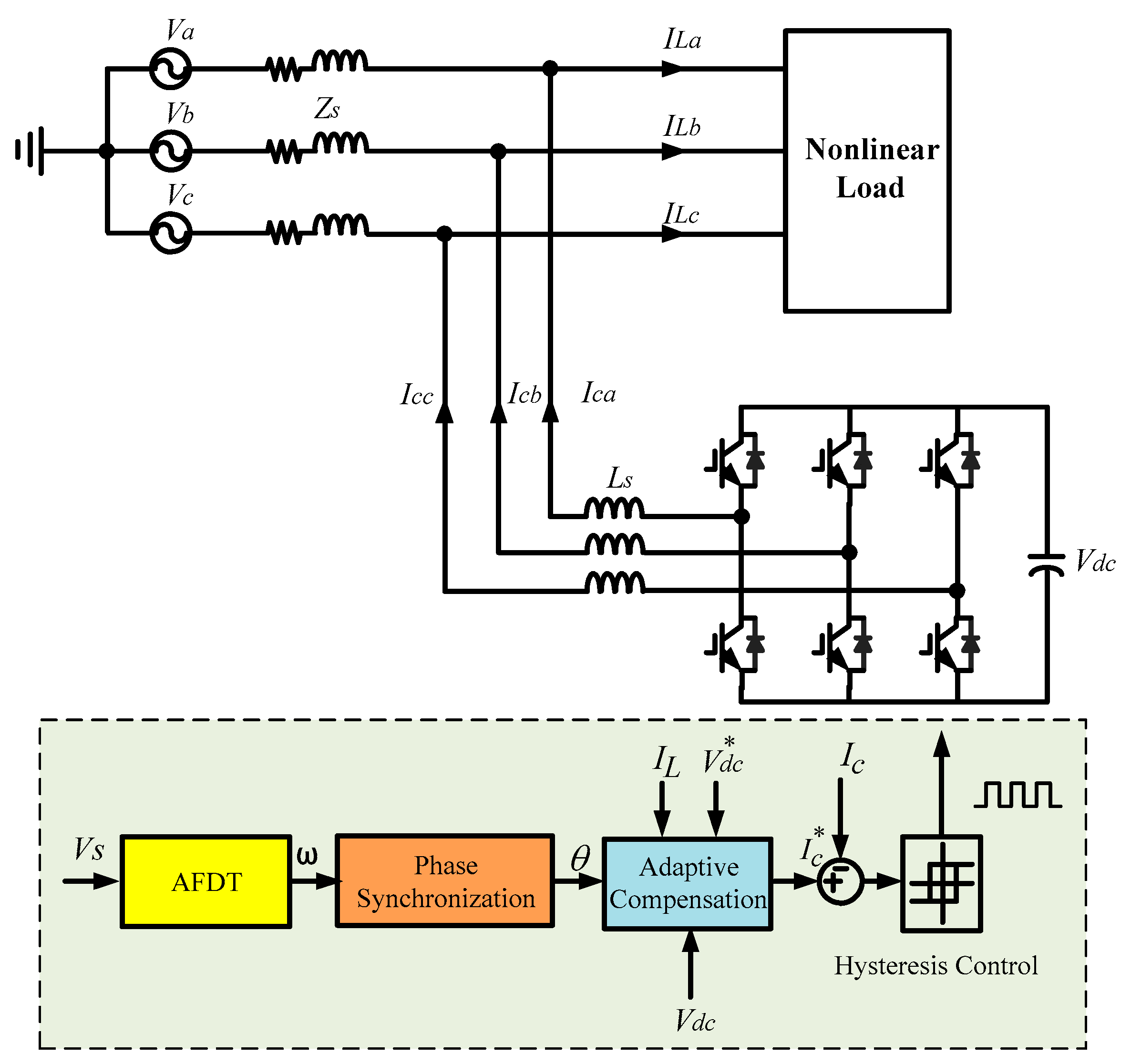
Figure 1 depicts the proposed adaptive frequency-based reference compensation current control strategy of three-phase SAPF, where
Vdc is the DC-link voltage of SAPF capacitor,
Zs is the line impedance,
ILa,
ILb, and
ILc are the three-phase nonlinear load currents extracted from voltage source
Va,
Vb, and
Vc,
Ic is the compensation current, and the superscript * represents the desired command. The proposed control strategy of SAPF can be mainly divided into three stages, including the adaptive frequency detection technique (AFDT), phase synchronization, and adaptive compensation.
2.1. Adaptive Frequency Detection Technique (AFDT)
In general, the compensation of SAPF is synchronized to the nominal power system frequency. Once the power variation of nonlinear loads is present, the power system frequency would be deviated. In this way, the compensation performance of SAPF would be deteriorated. To enhance the accuracy of synchronization and calculation of reference compensation current, the adaptive frequency detection technique for the power system frequency is proposed in this section.
Suppose the power signal through the filter
sn can be expressed as
where
is the power system angular frequency,
is the amplitude,
is the sampling period,
is the phase angle, and
N is the number of samples. Equation (1) can also be represented in the complex form as
where
,
, and * represents the complex conjugate. According to the 2nd-order autoregressive model, the total squared error
E for the signal estimation can be illustrated with the linear combination of three successive samples in Equation (3), where
x is the parameter for the estimation [
14].
In addition, the transfer function of 2nd-order autoregressive model can be given by
To minimize the estimation error, the following relationship shall be met.
Then,
x can be obtained as
By substituting Equation (6) into Equation (4) and solving
z, the power system angular frequency
can be calculated in Equation (7) adaptively based on the sliding window of
N samples.
2.2. Phase Synchronization
To perform the accurate nonlinear load current compensation, the phase synchronization between the reference compensation current and the voltage source is necessary. In this paper, the dual second-order generalized integrator phase-locked loop technique (DSOGI-PLL) is directly applied, which is based on the second-order generalized integrator (SOGI), as depicted in
Figure 2, where PI is the proportional-integral controller. This method is more accurate than the traditional PLL technique for the harmonic interference condition, as proven in [
13]. However, the synchronization accuracy is dependent on the power system angular frequency
ω, as shown in the architecture of
Figure 2. Therefore, the estimated power system angular frequency in Equation (7) would be used to modify the detected synchronization phase angle
θ.
2.3. Adaptive Linear Neural Network (ALNN)
Adaptive linear neural network (ALNN) is the single-layer neural network, where the activation function is linear. With the linear combination of input data and corresponding coefficients (weights), the mapping relationship between input and output can be established [
15,
16]. In this paper, the ALNN is applied to extract the reference compensation current according to the load current and detected synchronization phase angle in
Section 2.2.
For the load current
ILp (
p =
a,
b,
c, which means the phase sequence), the discrete form of the estimated current signal with the power system frequency
f can be expressed by Equation (9), where
M is the estimation order representing the number of considered harmonics,
,
,
,
Am and
ϕm are the amplitude and the phase angle of the
mth harmonic,
Ts is the sampling period, and
n is the time index. The architecture of ALNN is depicted in
Figure 3.
From the architecture of
Figure 3, the estimated load current signal
ILp_n at time
n can be represented by Equation (9), where
and
.
Then, the updated weight
including the information of amplitude and phase angle (extracted signal) can be adaptively adjusted according to the practical load current signal
by the following weight updating process.
where
η is the learning rate and
en is the estimation error between the estimated and practical signals. In this way, the amplitude and the phase angle of the
mth harmonic can be obtained in Equation (11).
2.4. Adptive Compensation
The final stage of proposed adaptive frequency-based reference compensation current control strategy is the adaptive compensation, which determines the required reference compensation current of SAPF and performs the DC-link voltage regulation. The block diagram of proposed ALNN-based reference compensation current control strategy is displayed in
Figure 4. In this architecture, the maximum amplitude value of the fundamental frequency current (
,
, or
) would be extracted from the load current at each phase based on the synchronized phase angle
obtained by the DSOGI-PLL. Then, the reference source currents
,
, and
, can be accurately obtained by multiplying (
Aavg +
Adc) and the three-phase unit positive-sequence fundamental currents, where
Aavg is the average of
,
,
and
Adc is the difference of DC-link voltage regulation with PI controller. Then, the reference compensation currents
,
, and
can be obtained with Equations (12)–(14) and adaptively regulated according to the load currents.
3. Case Studies
To evaluate the effectiveness of proposed control strategy for SAPF, the comprehensive case studies implemented with the HIL mechanism are performed in this section, as depicted in
Figure 5. The testing results with the traditional instantaneous reactive power compensation control technique (p-q method) of [
6], the sliding DFT, and proposed control strategy are discussed. In this experimental system, the unbalance nonlinear load composed of a six-pulse rectifier, a Y-connected resistor–inductor load, and the unbalanced interharmonic load connected to a converter based on the sinusoidal pulse-width modulation control and then in series with a motor are built in the MATLAB/Simulink model. The implemented 2-kVA SAPF hardware is based on Texas Instruments TMS320F28335 Digital Signal Processor (DSP). In the HIL mechanism, the signal extraction and control are performed via Advantech PCI-1720 Digital-to-Analog (D/A) Converter and PCI-1716 Analog-to-Digital (A/D) Converter, respectively. According to IEEE Std. 519-2014, the two indices, total harmonic current distortion (
THDI) and unbalance rate (
UR) listed in Equations (15) and (16), are applied for the evaluation of SAPF compensation performance, where
I1 and
Irms are the fundamental component and root-mean-squared (RMS) component of source current,
Iavg is the average of three-phase source currents
Isa,
Isb, and
Isc, and
Max(·) is the operator to obtain the maximum value.
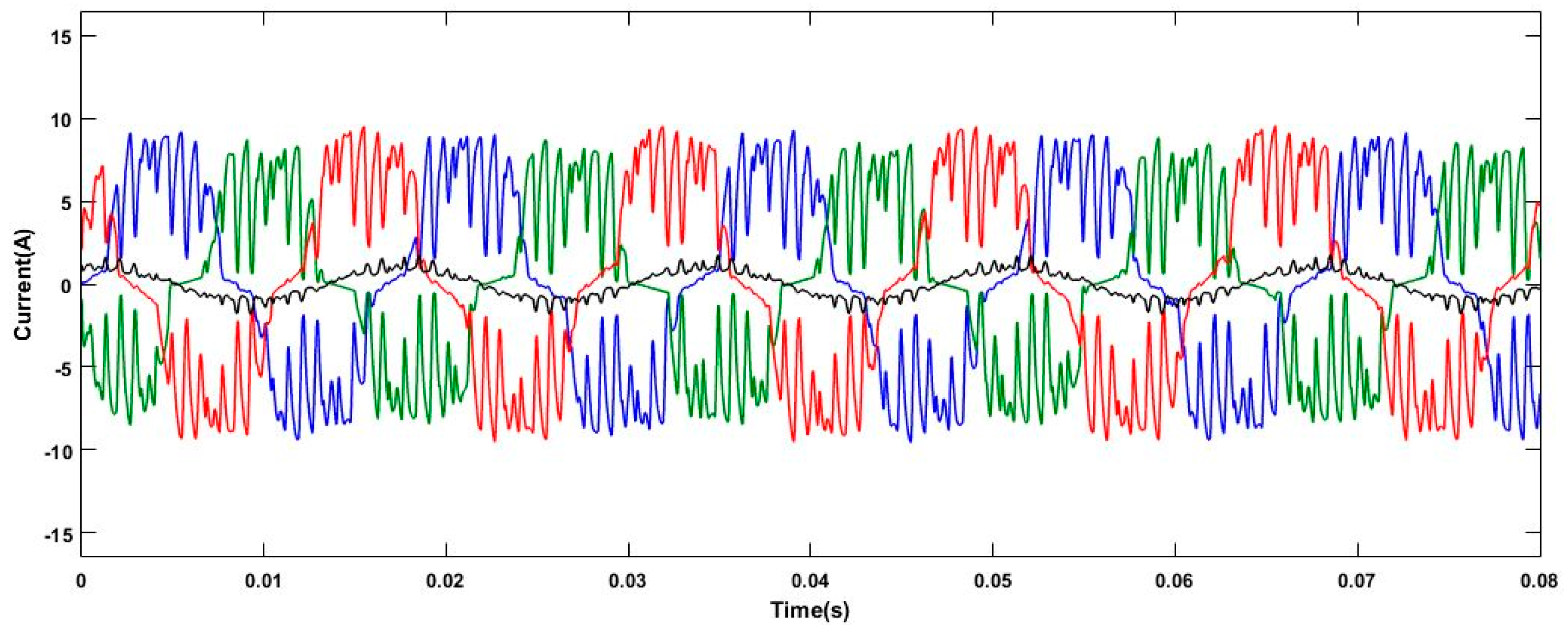
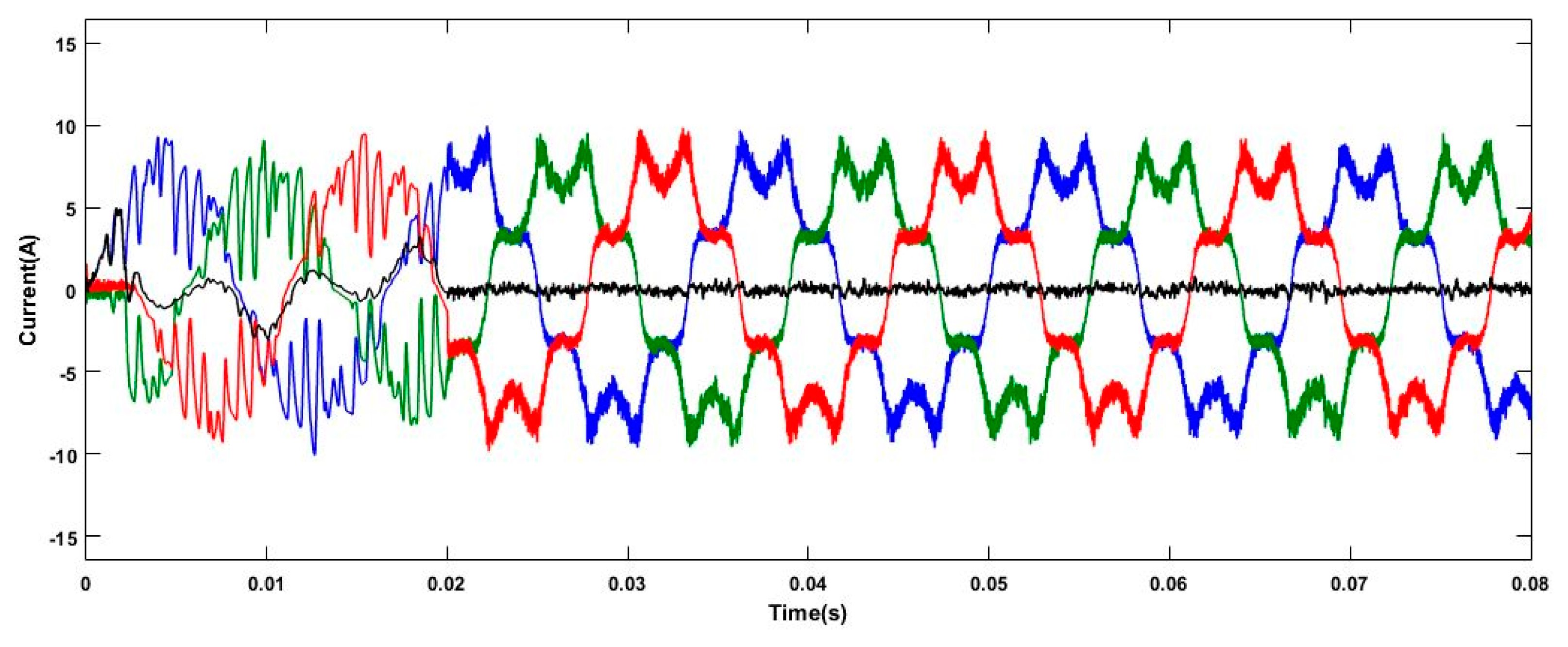
3.1. Case 1: Unbalanced Nonlinear Loads under Nominal Source Voltage
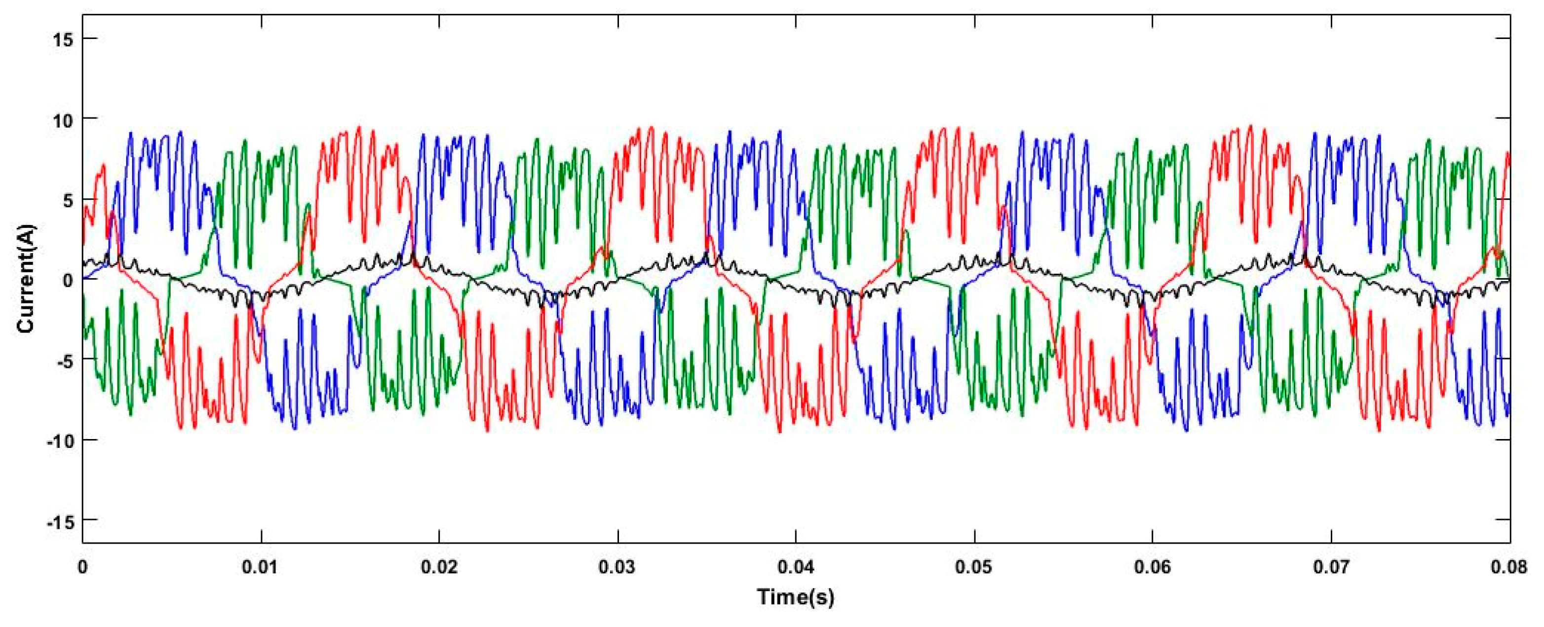
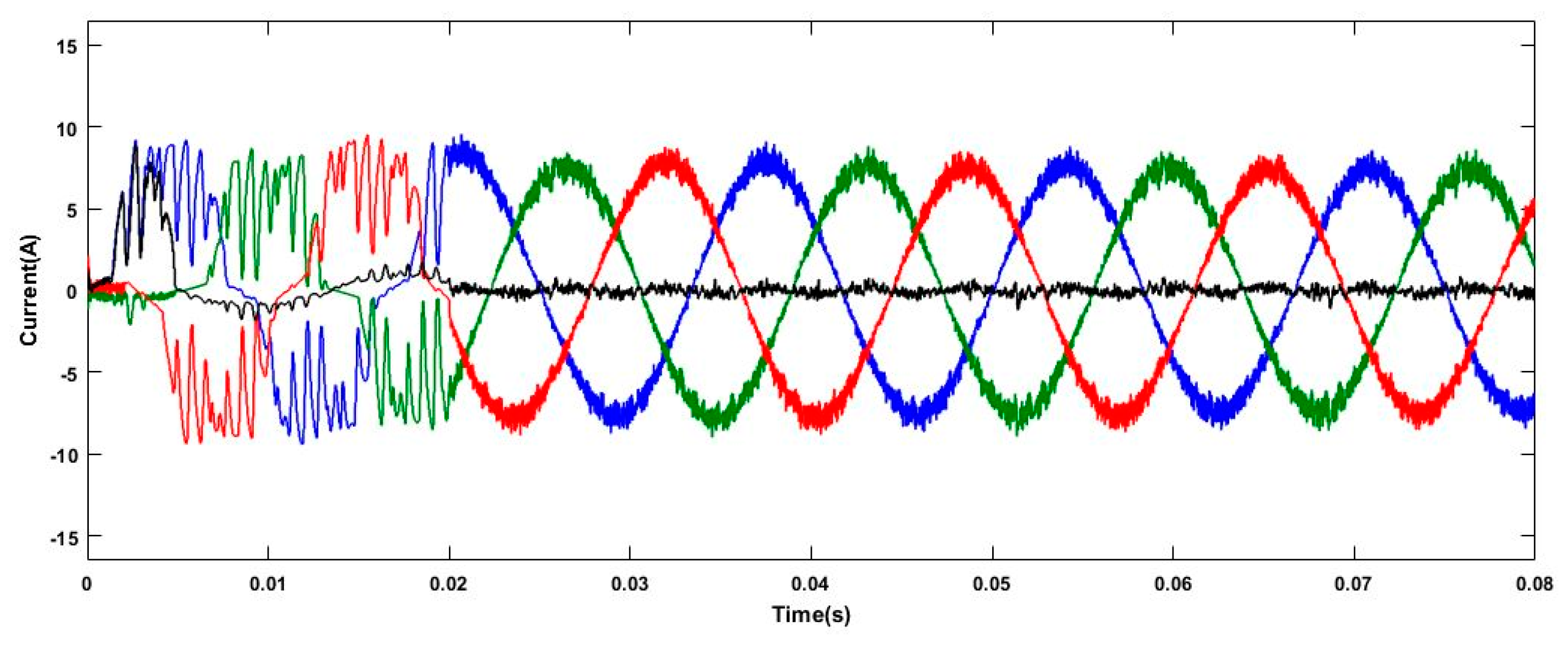
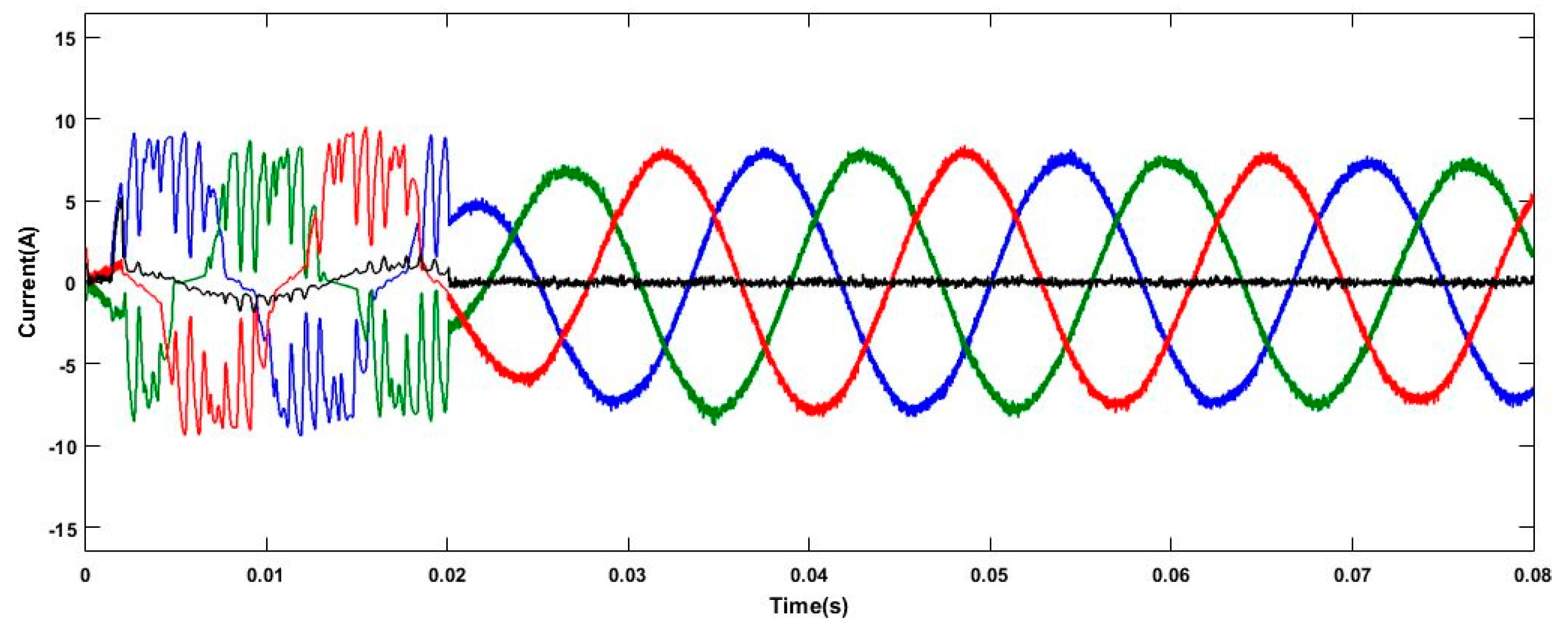
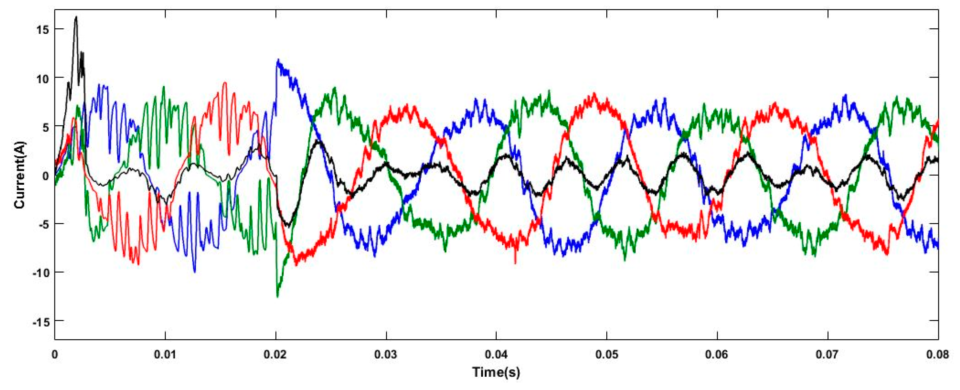
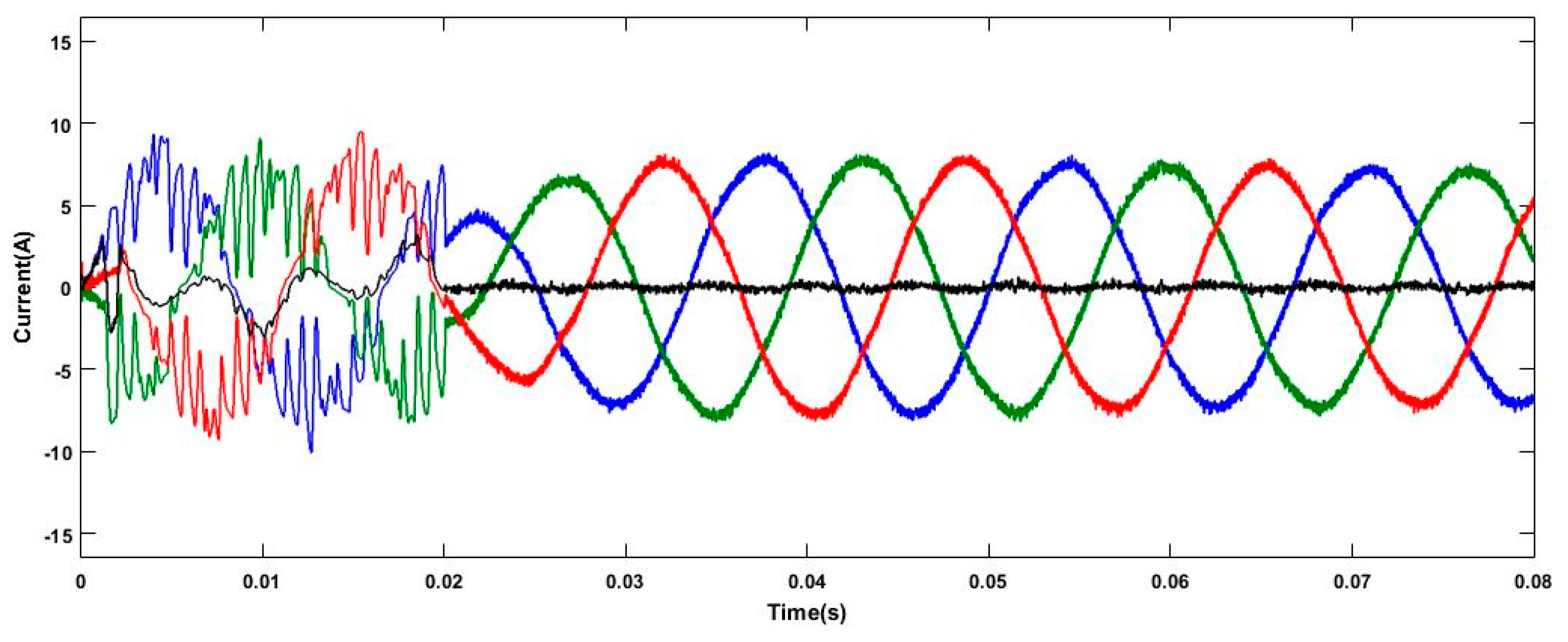
In this case, the power system is suffered from the unbalanced harmonic and interharmonic distortion under the nominal source voltage. The SAPF is connected to activate the compensation at 0.02 s. The experimental results without compensation, with the traditional p-q method, sliding DFT, and proposed control strategy are displayed in
Figure 6,
Figure 7,
Figure 8 and
Figure 9 and
Table 1. From the testing results, it is realized that the proposed strategy can achieve good power quality under unbalanced harmonic distortion compared with the traditional p-q method. From
Table 1, it is also found that only the proposed control strategy can effectively reduce the harmonic distortion, which is in compliance with the 5%-
THDI maximum limit of IEEE Std. 519-2014. In this case, the compensation results of sliding DFT would be deteriorated due to the interharmonic current, where the high frequency resolution is required to perform the correct compensation. For the time-varying interharmonic currents in this case, it is impractical for sliding DFT to determine the suitable frequency resolution.
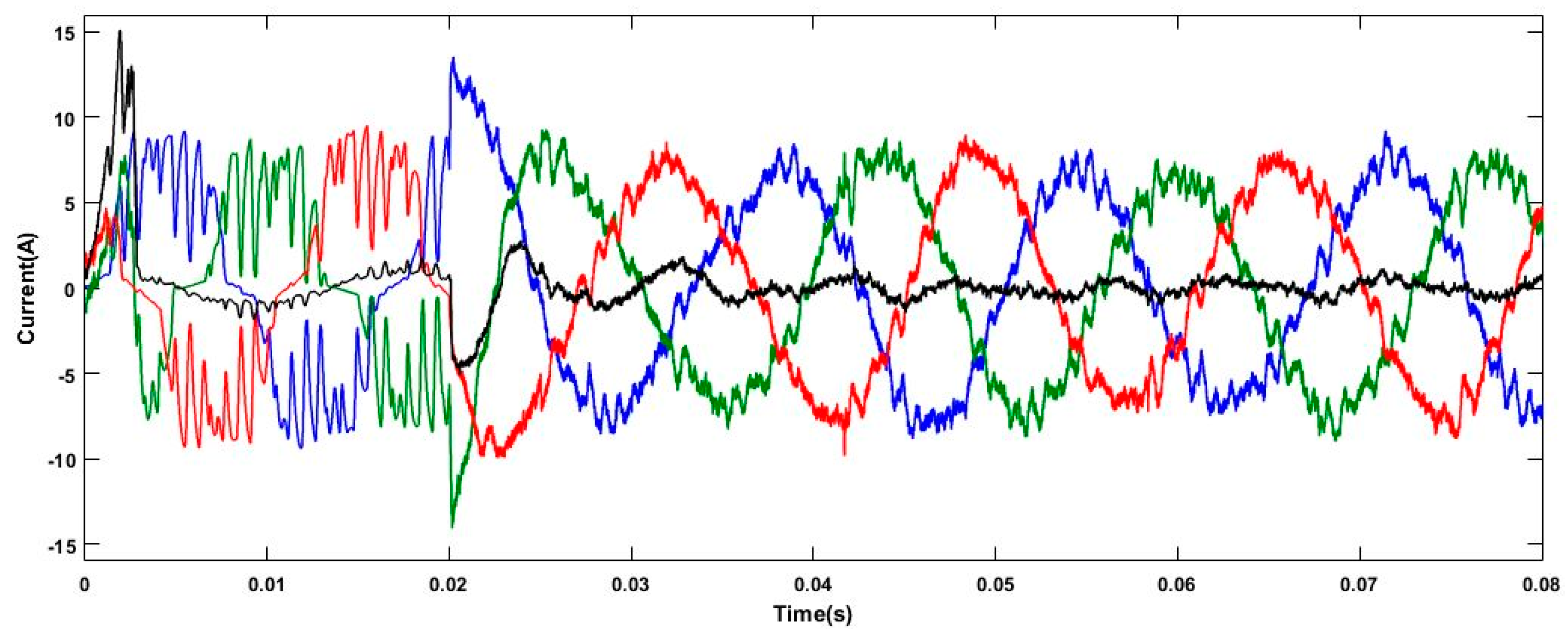
3.2. Case 2: Unbalanced Nonlinear Loads under Power System Frequency Deviation
In this case, the power variation of unbalanced nonlinear loads with harmonic and interharmonic distortion is taken into account, where the power system frequency is deviated from the nominal value 60 Hz to 59.7 Hz due to the load variation and the SAPF is connected to the system at 0.02 s. From the experimental results in
Figure 10,
Figure 11,
Figure 12 and
Figure 13 and
Table 2, it is realized that the proposed control strategy can effectively perform the compensation of distorted source current via the frequency-deviation regulation of AFDT in
Section 2.1. On the contrary, the traditional p-q method would lead to the compensation error due to the power system frequency deviation. For the sliding DFT, the frequency resolution is dependent on the size of analysis sliding window. As a result, it is impractical for sliding DFT to detect the power system frequency deviation by using a long-duration window. The spectral leakage would be present for the insufficient frequency resolution (size of sliding window). Therefore, the compensation result of sliding DFT would be deteriorated due to the power system frequency deviation.
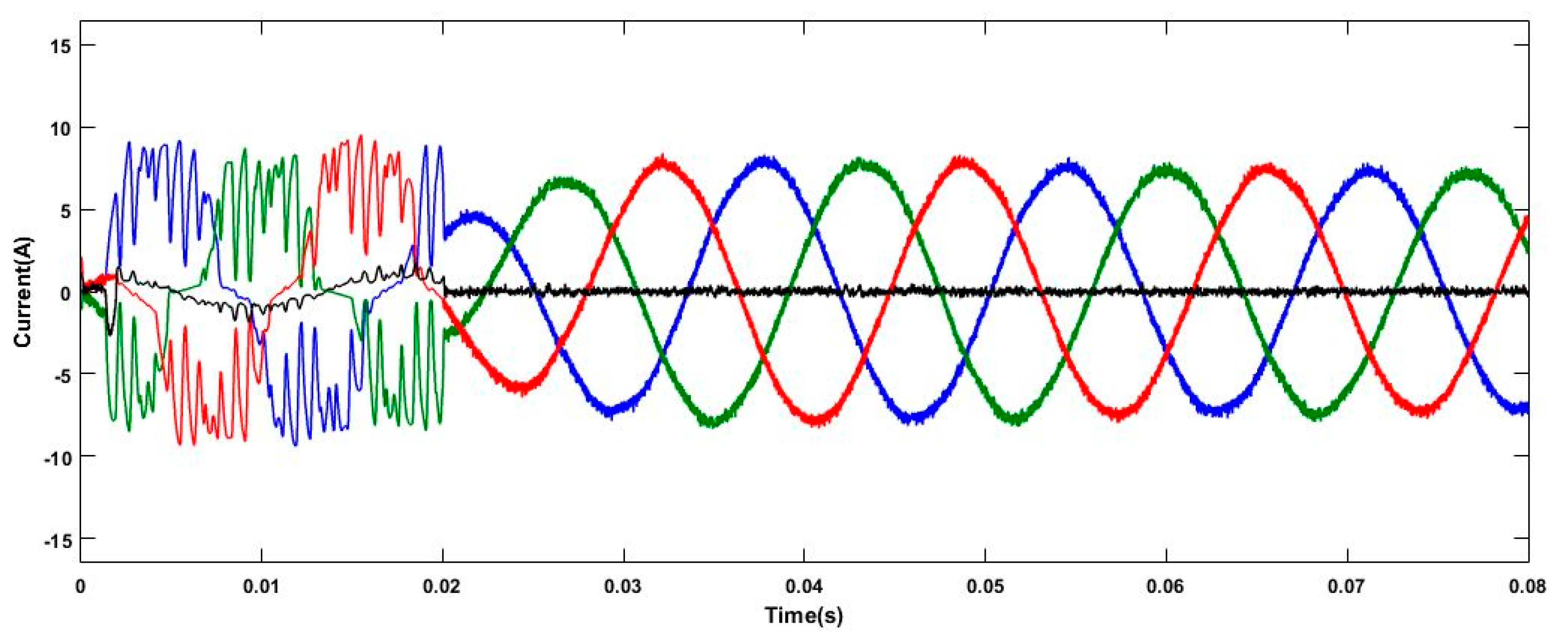
3.3. Case 3: Unbalanced Nonlinear Loads under Distorted Source Voltage
In this case, the power system is suffered from the unbalanced harmonic and interharmonic distortion and distorted source voltage. The SAPF starts to perform the compensation at 0.02 s. From the experimental results in
Figure 14,
Figure 15,
Figure 16 and
Figure 17 and
Table 3, it is realized that the proposed control strategy can effectively perform the compensation of distorted source current, even under the condition of distorted source voltage. This is because the positive-sequence component of source voltage can be extracted in the proposed adaptive compensation mechanism of
Figure 4. The traditional p-q method and sliding DFT would lead to the serious compensation error since the calculation of reference compensation current is based on the nominal source voltage.
4. Conclusions
In this paper, the adaptive frequency-based reference compensation current control strategy for SAPF is proposed. Through the AFDT, the power system frequency deviation resulted from the power variation of unbalanced nonlinear loads can be accurately detected. The obtained power system frequency can be used to regulate the phase synchronization of SAPF. Then, the proposed adaptive compensation mechanism would effectively enhance the power quality since the reference compensation current of SAPF can be accurately and adaptively obtained along with the variation of unbalanced nonlinear loads. In addition, the compensation performance can be maintained under the distorted source voltage due to the extraction of positive-sequence component in the proposed adaptive compensation mechanism. Compared with the traditional p-q method and sliding DFT, the compensation performance of proposed control strategy is superior to make the total harmonic current distortion and unbalance rate complied with the specification limits of IEEE Std. 519-2014.


