Article

Mining-Induced Failure Criteria of Interactional Hard Roof Structures: A Case Study

1
Henan Key Laboratory for Green and Efficient Mining & Comprehensive Utilization of Mineral Resources, Henan Polytechnic University, Jiaozuo 454000, China
2
State Key Laboratory of Coal Resources and Safe Mining, China University of Mining & Technology, Xuzhou 221116, China
3
State Key Laboratory of Coal Mine Disaster Dynamics and Control, College of Resources and Environmental Science, Chongqing University, Chongqing 400044, China
*
Authors to whom correspondence should be addressed.
Energies 2019, 12(15), 3016; https://doi.org/10.3390/en12153016
Submission received: 30 June 2019 / Revised: 26 July 2019 / Accepted: 1 August 2019 / Published: 5 August 2019
(This article belongs to the Section L: Energy Sources)

Abstract

:
Due to the additional abutment stress, interactional hard roof structures (IHRS) affect the normal operation of the coal production system in underground mining. The movement of IHRS may result in security problems, such as the failure of supporting body, large deformation, and even roof caving for nearby openings. According to the physical configuration and loading conditions of IHRS in a simple two-dimensional physical model under the plane stress condition, mining-induced failure criteria were proposed and validated by the mechanical behavior of IHRS in a mechanical analysis model. The results indicate that IHRS, consisting of three interactional parts—the lower key structure, the middle soft interlayer, and the upper key structure—are governed by the additional abutment stress induced by the longwall mining working face. The fracture of the upper key structure in IHRS can be explained as follows: Due to the crushing failure, lower key structure, and middle soft interlayer yield, the action force between the upper and lower key structures vanishes, resulting in fracture of the upper key structure in IHRS. In a field case, when additional abutment stress reaches 7.37 MPa, the energy of 2.35 × 10⁵ J is generated by the fracture of the upper key structure in IHRS. Under the same geological and engineering conditions, the energy generated by IHRS is much larger than that generated by a single hard roof. The mining-induced failure criteria are successfully applied in a field case. The in-situ mechanical behavior of the openings nearby IHRS under the mining abutment stress can be clearly explained by the proposed criteria.

1. Introduction

With the development of clean utilization technologies, coal will always provide energy sources for the social development [1]. To ensure the efficient operation of coal production systems, security maintenance of entries in underground mining is extremely important, including large deformation control, rock burst forecast, and other early warnings of dynamic disaster [2,3,4]. As the development of the longwall mining, many entries are arranged along the side of a gob with a protection of coal pillar or artificial wall, so as to cope with the mining-induced movement of the hard roof structures [5,6,7]. Figure 1 schematically describes entry conditions when extracting coal from Panel 2. Tail entry provides auxiliary transportation and ventilation function for Panel 2. A coal pillar or artificial wall is built in the south of tail entry; and the coal mass of Panel 2 is located in the north of Tail entry. Gob 1 is located near the coal pillar. The spontaneous caving method was used to handle the roofs in Gob 1 [8]. To effectively control the deformation of tail entry in the strong mining pressure zone, it is important to understand the mechanical behavior of the hard roof structures above the side of Gob 1 during retreat of the mining working face of Panel 2.
Mechanical behavior of hard roof structures mainly refers to the separation, fracture, rotation, slipping, and yielding when the stress reaches the strength of structures [9,10,11,12,13,14,15,16,17]. At present, stability analyses of mechanical behavior are mainly concentrated on the single structure in one layer. Interactional effects between the hard roof structures in the different layers are rarely studied [18,19,20,21,22,23]. Shabanimashcool and Li [24] discussed the relationship between the horizontal in-situ stress and the buckling or crushing failure of the voussoir beam structures, which provide a mechanical method for the analysis of the interaction of structures in one layer. Zhang et al. [25] found that sink and rotation of the cantilever roof structure above the side of the gob generates severer pressure for the entry along the side of the gob; while the effects of this structure movement on the upper cantilever roof structure were ignored. Guo et al. [26] determined the support resistance assuming that the hard roof structures play a loading role in the lower supports together; while interactional effects between the structures were ignored. Yang and Liu et al. [27,28,29,30] demonstrated that the breakage of layered hard roof group structures led to severe concussion and determined the calculation method of the support resistance during the collapse process of multiple roofs. However, the effect of one structure caving on the other structural movement was ignored.
In-situ monitoring data in the field are widely used to predict and analyze the strong mining pressure of the entry influenced by the movement of hard roof structures [31,32,33]. Nevertheless, mechanical behaviors of hard roof structures can result in the error of the dynamic disaster early warning. Lu et al. [34] established the early warning method of the coal-rock dynamic disasters induced by the double-layer and thick igneous strata separation and fracture based on the in-situ microseismic signals. However, the horizontal and vertical positioning errors of microseismic signal sources cannot be eliminated clearly by optimizing the arrangement of the geophones. Wang et al. [35] provided a theoretical method for forecasting the location of rockburst induced by the fracture in the main roof by the in-situ microseismic monitoring results, but the positioning error of the microseismic signal sources was proved to be up to 10 m by blast experiments in the field. Bai et al. [36] proved that the lateral cantilever structure can produce supporting stress through field monitoring and numerical calculation. Under the action of the supporting stress, the entry along the side of the gob is vulnerable to large deformation and rock burst. However, the vibration signal from the structural fracture was ignored [37]. Compared with monitoring technologies in the field, mechanical behaviors of hard roof structures have a great influence on the large deformation control of entries.
To achieve pressure relief for the underground space, research on the controlling of hard roofs has been conducted recently. Zhang et al. [38] demonstrated that the hard-roof-induced face burst can be reduced effectively by preventing the roof-caving movement through solid backfilling mining method. Zhou and Li et al. [39,40] determined the reasonable backfilling ratio to control the hard roof deformation and reduce the mining abutment stress. He et al. [41] analyzed the rockburst prevention by cutting the hard roof directionally in advance under mechanical behaviors of the deep-hole directional fracturing of hard roof. To reduce the effect of the fracture failure of the overlying hard-thick sand-stone main roof on the gas permeability in the mining coal seams, Wang et al. [42] recommended shortening the hanging length of the main roof failure span using hydraulic presplitting. Zhang, et al. [43] determined the breaking form, order, step of the over roofs based on the hinge balanced cantilever beam structure model with the directional blast technology. Yu et al. [44] proposed the fracturing high-level hard rock strata using the ground hydraulic action. To achieve pressure relief of the entry nearby the side of the gob, the reasonable length and fracture location of the lateral cantilever structure were determined by mechanical analysis, but the influences of remolded structures by human on the movement of the upper structures was not considered [45,46,47].
In this work, a 2D physical model with plane-stress conditions was established to reveal the configuration and loading conditions of the interactional hard roof structures over the side of the Gob 1. After that, mining-induced failure criteria were proposed to describe the mechanical behavior of the structures, and the criteria were validated by a mechanical analytical model. Finally, the criteria were applied to analyze hard roof structures in a field case. The results contribute to understanding the strong mining pressure of the tail entry in front of the mining working face.

2. Interactional Hard Roof Structures (IHRS)

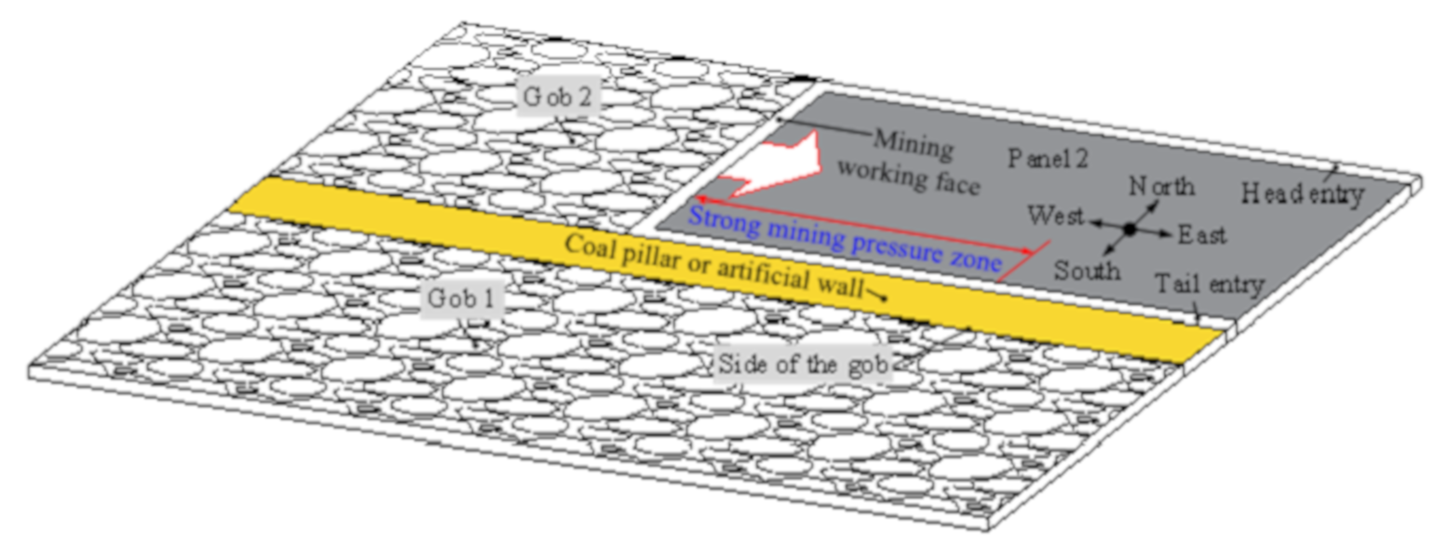
2.1. Establishment of IHRS

IHRS are established based on a simple two-dimensional physical model under the plane stress condition. The physical model is 2.5 m in length, 0.3 m in width, and 2 m in height, as shown in Figure 3. The normal displacement is fixed in the floor boundary and two-sided boundaries with the frame. The front and back boundaries of the model are in a free state. The vertical load 0.056 MPa is applied to simulate the overburden loads through 20 loading rams in the top of the model. According to the similarity theory [48], the similarity criteria must be satisfied in the physical modeling as shown in Equation (1). For this experiment, similarity ratios of geometry, density, strength, and time are determined as 160, 1.53, 244.8, and 12.65, respectively.
{ C σ C ρ C L = 1 C L = L p L m C σ = σ p σ m C ρ = ρ p ρ m C t = C L C L
where CL, Cσ, and Ct is the similarity ratio of geometry, strength, and time, respectively. Cρ is the density similarity ratio of the prototype and the model. Lp, σp, and ρp represents the dimension, strength and density of the rock strata in the field, respectively; Lm, σm, and ρm represents the dimension, strength, and density of the rock strata in the model, respectively.
Eight materials with different deformability and strength were used to simulate the mechanical behavior of geological strata, including mudstone, coal seam 15, limestone, mudstone group 1, fine sandstone, mudstone group 2, medium sandstone, and mudstone group 3. Materials were mingled with sand, gypsum, water, calcium carbonate, and mica powder. Under the condition of the uniaxial compression test and the strength similarity ratio, the ratio of the material contents was determined based on the existing results [49]. In this work, there were eight materials, as shows in Table 1 and Table 2. In total, 1733.91 kg sand, 169.10 kg calcium carbonate, 234.49 kg gypsum, and 25 kg mica powder were used in this model.
Eight physical geological layers were modeled and compacted one by one, and every geological layer was separated with certain mica powder. After two months of the model completion, the longwall face was retreated successively from the panel center to panel boundary to simulate the mechanical behavior of hard roofs. In each stage, 50 mm long coal was excavated by using a mini shovel after 5 min. Then, the next excavation was conducted after 20 min. A universal camera was used to directly observe and record the physical configuration and loading conditions of hard roof structures. The typical results are shown in Figure 4 and Figure 5. The detailed characteristics of IHRS are described in Section 2.2.

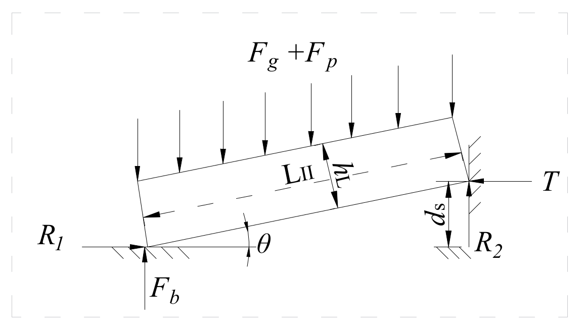
2.2. Physical Configuration and Loading Conditions of IHRS

IHRS, consisting of a lower key structure, middle soft interlayer, and upper key structure, are governed by the mechanical behavior of the lower and upper key structures, as shown in Figure 6. The lower key structure, loaded by the middle soft interlayer, is stable with the supports of the lower structure I, the lower structure III, and the gob floor. The middle soft interlayer, supporting the upper key structure partly and loading the lower key structure entirely, is the transfer medium of the force between the upper and lower key structures. The upper key structure, loaded by the overlying strata, is stable with the supports of the upper structure II, the middle soft interlayer, and the compaction rock mass. The interactional upper structure II and upper structure III, loaded by the overlying strata, are stable with the supports of the upper key structure.

2.3. Mining-Induced Failure Criteria of IHRS

Mining-induced failure criteria are proposed based on the physical configuration and loading conditions of IHRS. As additional abutment stress loaded on the upper key structure increases, the supporting stress transferred from the middle soft interlayer to the lower key structure shows an increasing trend. The lower key structure and the middle soft interlayer fall down when crushing failure or slippage failure is generated in the contact face between the lower key structure and the lower structure I. The upper key structure is subjected to the new fracture movement when the action force between the upper and lower key structure vanishes.
The mining-induced failure criteria for IHRS can be divided into three processes, as shown in Figure 7. In Process 1, the gradual increase of additional abutment stress, which belongs to IHRS boundary condition, is the main external factor for the failure of IHRS. In process 2, the yielding at the lower key structure where crushing failure or slippage failure occurs on the contact surface is the main internal factor of IHRS failure. The fracture of the upper key structure, induced by the shear failure or tensile failure of the rock materials, is another internal factor for the failure of IHRS in Process 3. The crushing failure or slippage failure of the contact face is the result of Process 1 and the cause of Process 2. Similarly, the vanishing of the action force between the upper and lower key structures is the result of Process 2 and the cause of Process 3.

3. Validation of the Mining-Induced Failure Criteria

3.1. Process of the Increasing Additional Abutment Stress

The additional abutment stress, which is generated from overlying loads above the gob, has a loading effect on the rock around the gob [50]. With the distance from the working face to the location of minimum additional abutment stress, the additional abutment stress increases gradually. Then, it decreases gradually as the distance to the mining working face decreases from the beginning of the maximum value, as shown in Figure 8 [5]. There are four feature points on the curve of the additional abutment stress, including the points of the residual value (0, y1), the maximum value (w, y2), the any value (d3, y3), and the minimum value (∞, y4).
F a = L I { a 1 d + a 2 - γ H d < w a 3 e a 4 ( w d ) + a 5 - γ H d w
where Fa is the additional abutment stress in the front of the mining working face, kN; a1, a2, a3, a4, and a5 are parameters of the mathematical model, which can be obtained in Equation (3); d is the distance to the mining working face, m; w is the distance between the working face and the location of the maximum value of the additional abutment stress, m; γ′ is the average volume weight of the geological strata, which can be calculated by the ratio of the cumulative sum of every strata’s volume weight, thickness, and the cumulative thickness of geological strata, kN/m3; H is the cumulative thickness of the geological strata, m.
{ a 1 = ( y 2 y 1 ) w a 2 = y 1 a 3 = y 2 y 4 a 4 = 1 w d 3 ln y 3 y 4 y 2 y 4 a 5 = y 4

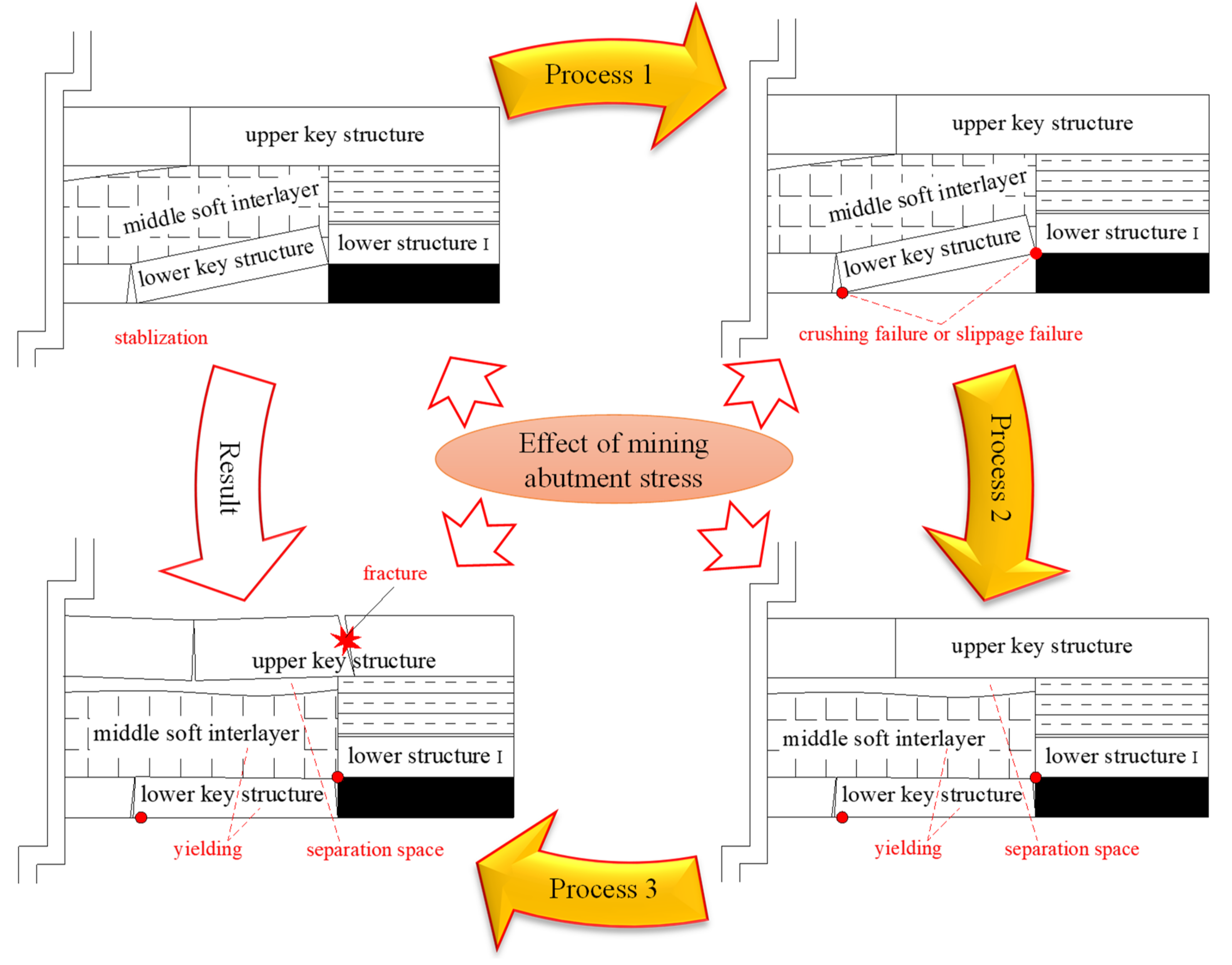
3.2. Process of the Yielding for the Lower Key Structure

Since the lower structure tends to rotate around the base corner under the action of additional abutment stress, the lower key structure will lose the support of the lower structure III. The mechanical model is shown in Figure 9. The slippage failure occurs in lower key structure when the horizontal friction force R1 and the vertical friction force R2 are insufficient; crushing failure occurs when the crushing strength of the contact face is insufficient.
In Figure 9, Fg is the weight of the middle soft interlayer and the lower key structure, kN. Fg can be calculated by Equation (4). Fp is the the loading transferred from the upper key structure, kN; R1 is the horizontal friction force between the lower key structure and the gob floor, kN; Fb is the vertical support force of the gob floor, kN; R2 is the vertical friction force between the lower key structure and the lower structure I, kN; T is the horizontal support force of the lower structure I, kN; hL is the thickness of the lower key structure, m.
F g = γ L ( L I I h L + L I I h L S cos θ )
where γL is the average volume weight of the lower key structure and the middle soft interlayer, kN/m3. γL can be calculated by the ratio of the cumulative sum of their volume weight and thickness and the cumulative thickness of them, kN/m3; hLS is the thickness of the middle soft interlayer, m.
In the mechanical analysis, the equilibrium equation can be obtained in Equation (5). When the horizontal friction force R1 reaches the ultimate value (Fbtanφf) and the vertical friction force R2 reaches the ultimate value (Fbtanφb), slippage failure occurs in the lower key structure. Therefore, the first and second relationships are obtained, as shown in Equation (5). According to the static equilibrium, the resultant force along the vertical direction, the resultant force along the horizontal direction, and the resultant moment of any point all equal to zero, then the third, fourth, and fifth relationships are obtained in Equation (5). In addition, when the crushing stress (T/a) reaches the ultimate value (ηpσc), crushing failure of structure occurs, then the sixth relationship is obtained in Equation (5). After solving Equations (4) and (5), the criteria can be obtained in Equations (6) and (7) to protect the lower key structure from slippage failure and crushing failure.
{ R 1 F b tan φ f R 2 T tan φ b R 1 = T F b = F g + F p R 2 T L I I sin θ + R 2 L I I cos θ = ( F g + F p ) ( L I I cos θ h L sin θ ) / 2 T / a η p σ c
f 1 = h L L I I 1 2 tan θ tan φ f tan φ b tan φ f tan θ + tan θ tan φ b tan φ f 0
F p η p σ c ( h L d s ) ( L I I sin θ + L I I cos θ tan φ b ) L I I cos θ h L sin θ γ L ( L I I h L + L I I h L S cos θ )
where tanφf is the frictional coefficient of the gob floor; tanφb is the frictional coefficient of the lower structure I; a is the area of the contact face between the lower key structure and lower structure I as shown in Figure 7, which can be calculated by Equation (8) [51], m2; ηp is the ratio of the crushing strength and the uniaxial compressive strength for the lower key structure; σc is the uniaxial compressive strength of the lower key structures, kPa; f1 is the criteria of the slippage failure of the lower key structure; LII can be calculated by the empirical Equation (9) [52], m; θ can be calculated by Equation (10).
a = 1 2 ( h L L I I sin θ )
L I I = 2 h L 17 R T 3 q ( 100 R T h L 2 3 s q + 102 10 h L s R T 3 q )
θ = arcsin ( d s L I I )
where RT is the tensile strength of the lower key structure, kPa; q is the uniform stress loaded on the structures, kPa.
Once the strength exceeds the loading (see Figure 6), the hard roof can fracture into several parts. After that, the oblique part will contact with the adjacent part. This area is called the contact face, and it can be calculated by Equation (8). In addition, the oblique part is the lower key structure, whose length is related to the thickness hL, tensile strength RT, loading on the hard roof q, and length of the gob s. Then, the length of the lower key structure can be calculated by Equation (9). Finally, the dip angle of the lower key structure θ is established based on the mechanical model in Figure 9.

3.3. Process of the Fracture for the Upper Key Structure

The mechanical models of the upper structures are shown in Figure 10. When the vertical friction force R cannot support the overburden weight, slippage failure occurs in the upper structure II and upper structure III; when the crushing strength of the contact face cannot support the crushing force, crushing failure occurs. After the vanishing of the action force FP′ between the upper and lower key structures, the upper key structure is subjected to the tensile failure or shear failure when the bending moment and shear force are large enough.
In Figure 10, FgI′ is the weight of the upper soft interlayer and the upper key structure, and it can be calculated by Equation (11), kN; Fg′ is the weight of the upper soft interlayer, the upper structure II, and the upper structure III, and it can be calculated by Equation (12), kN; R is the friction force between the upper key structure and the upper structure II, kN; R′ is the shear force between the upper key structure and the upper compaction strata, kN; T′ is the horizontal crushing force of the upper structures, kN; M is the force moment of upper key structure, kN∙m. FP′ is the support force of upper key structure by the middle soft interlayer which is the reaction of FP, kN; hu is the thickness of the upper key structure, m.
F g I = γ u ( h u + h u s ) L I
F g = γ u ( h u + h u s ) ( 2 L I I + L I I I )
where γu is the average volume weight of the upper key structure and the upper soft interlayer, which can becalculated by the ratio of the accumulated volume weight of multi-layer strata to the accumulated thickness of these strata, kN/m3; hus is the thickness of the upper soft interlayer above the upper key structure, m.
In the mechanical analysis, the criteria are obtained in Equations (13) and (14) to protect the upper structure II and upper structure III from slippage failure and crushing failure. Similarly, the criteria are obtained in Equations (15) and (16) to protect the upper key structure from tensile failure and shear failure.
f 2 = h u L I I ( L I I + L I I I ) 2 L I I + L I I I tan φ b 0
f 3 = h u 2 γ u L I I ( L I I + L I I I ) η p σ c ( h u + h u s ) 0
σ max = 3 ( F g I + F a + F g F p ) L I h u 2 R T
τ max = 2 F g I + 2 F a + F g F p 2 h u [ τ ]
where f2 is the criterion of the slippage failure of the upper structure II and upper structure III; f3 is the criterion of the crushing failure of the upper structure II and upper structure III; σmax is the maximum value of the tensile stress in the upper key structure, kPa; τmax is the maximum value of the shear stress in the upper key structure, kPa; LII′ can be calculated by the empirical Equation (17) [52], m. This method is similar to the calculation of Equation (9) in Section 3.2; LIII′ can be calculated by the Equation (18), m. LIII′ is related to the length of the gob, the length of the upper key structure, and the length of the upper structure II, as shown in Figure 6. LI is assumed as ζ times of LII, m; tanφb′ is the frictional coefficient of the upper structures; ηp′ is the ratio of the crushing strength and the uniaxial compressive strength for the upper key structure; σc′ is the uniaxial compressive strength of the upper key structure, kPa; FgI′ can be calculated by the Equation (19), kN. The background of FgI′ is explained in Equation (12); Fg′ can be calculated by the Equation (12), kN; RT′ is the tensile strength of the upper key structure, kPa; [τ] is the shear strength of the upper key structure, kPa.
L I I = 2 h u 17 R T 3 q ( 100 R T h u 2 3 q ( s L I ) + 102 10 h u s L I R T 3 q )
L I I I = s 2 ( L I + L I I )
F g I = γ u ( h u + h u s ) L I

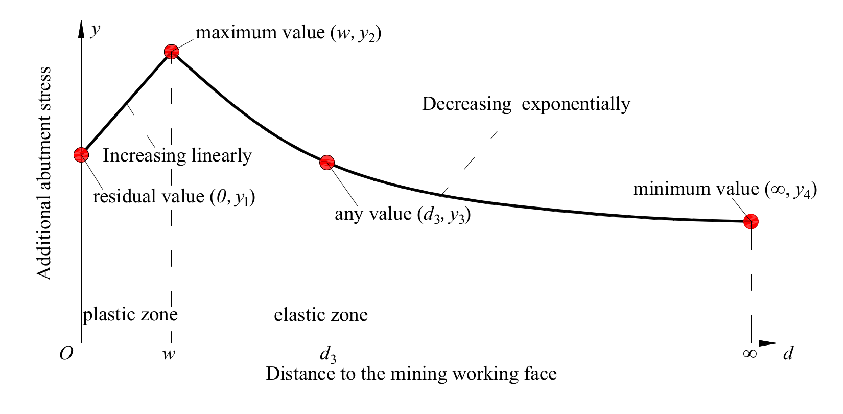
3.4. Limitation of the Additional Abutment Stress

When tensile failure is generated in the upper key structure, the deflection is δ times of the ultimate value, which can be used as the deformation compatibility condition. According to this condition, the limitation of the additional abutment stress can be calculated by Equation (20). The ultimate value of the deflection for the upper key structure can be calculated in Equation (21). The additional abutment stress reaches the limitation value, once the action force Fp′ between the upper and lower key structure reaches the limitation value of Fp in Equation (7). Thus, the final calculation method of the limitation of the additional abutment stress can be obtained by taking the Equation (7) and Equation (21) into Equation (20), as shown in Equation (22).
F a = F p F g I L I 4 F g 3 L I 8 δ ω max E I ( L I ) 4
ω max = R T L I 2 2 E h u
F max = η p σ c ( h L d s ) ( L I I sin θ + L I I cos θ tan φ b ) ζ L I I ( L I I cos θ h L sin θ ) 2 δ R T h u 2 + 4 ( s 2 ζ L I I ) F g 3 ζ 2 L I I 2 F g + F g ζ L I I

4. Application for a Field Case

4.1. Input Parameters

The method of the in situ investigation, laboratory test, and data fitting were used to determine the input parameters of IHRS. The results in a field case of Yangquan coal mine are shown in Table 3.

4.2. Output Results

The geometrical and mechanical characteristics of the lower key structure and upper key structure are calculated in Table 4. IHRS are in the stable state (f1 > 0, f2 < 0, and f3 > 0) when additional abutment stress equals to zero. However, failure of IHRS can occur when the additional abutment stress reaches the limitation value 7.37 MPa.

4.3. Failure Process

As shown in Figure 11a, when the additional abutment stress reaches 7.37 MPa at 23 m away from the longwall working face, yielding of the lower key structure and middle soft interlayer are induced. At the same time, as the force between the upper key structure and the lower key structure vanishes instantaneously, the shear stress is less than the shear strength, and the tensile stress is greater than the tensile strength of the upper key structure, as shown in Figure 11b,c. The fracture of upper key structure occurs due to the tensile failure.

5. Discussion

Liberating energy is an effective index to describe the interactional effects between hard roof structures. According to the method of the elastic deformation energy [53], the liberating energy from the upper key structure fracture can be calculated as 2.35 × 10⁵ J in Equation (23). If the force Fp does not exist, the upper key structure changes into a single structure and remains stable just when the additional abutment stress Fa′ changes into the upward tensile stress. Thus, the additional abutment stress Fa′ is a negative value in Equation (23). Liberating energy of 1.78 × 10⁵ J from the single upper key structure calculated by Equation (23) is clearly less than that of 2.35 × 10⁵ J from the upper key structure in IHRS.
V ε = R T ( L I ) 2 20 E h u ( 4 F g I + 4 F a + 5 F g )
The upper key structure is able to bear the additional abutment stress, when the force Fp exists, and it is subjected to tensile failure when the force Fp vanishes, as shown in Figure 11c. The tensile stress is distinctly larger than the tensile strength, even though the additional abutment stress equals zero (Figure 11a,c) when the force Fp vanishes. This result indicates that the tensile failure and liberated energy before the loading of the additional abutment stress can be generated by a single layer of the upper key structure. Besides, the greater liberating energy from the upper key structure in IHRS is also explained.
Mining-induced failure criteria can be used to effectively analyze the mechanical behavior of IHRS and determine the limitation value of the additional abutment stress. The results are helpful to protect the underground openings nearby IHRS from large deformation, such as roof sinking, floor heave, rib displacement, support failure, and even roof caving of the openings in 30 m away from the mining working face in Yangquan coal mine (Figure 12). The peak value of the deformation rate of the entry roof nearby IHRS is located between 20 m and 30 m from the mining working face. This curve shows an upward and downward trend, rather than a steady trend (Figure 13). The technologies of hydraulic fracturing to weaken hard roofs in advance have been gradually accepted in coal mines of China recently [54,55,56].
In mining engineering, there are two requirements for the application of the proposed mining-induced failure criteria: (1) There is a soft layer being sandwiched between the two interactional hard roof structures; (2) the equilibrium condition of structures should satisfy Equations (6), (13), and (14). Further, correlative parameters of IHRS need to be re-determined considering the varying geological conditions. For example, ds, the distance between the gob floor and the contact position of the lower structures, can be changed when the immediate roof is soft. In the physical model, unexcavated zones on both sides of the coal seam is used to reduce the influence of model boundary on IHRS. The model is not a standard two-dimensional stress model since free boundaries are exposed to air and subject to atmospheric pressure.

6. Conclusions

Mechanical behavior of the interactional hard roof structures (IHRS) has a great influence on the nearby underground openings in longwall mining engineering. IHRS consist of three parts: The lower key structure, the middle soft interlayer, and the upper key structure. The lower key structure, loaded by the middle soft interlayer, is the supporting part in IHRS. The middle soft interlayer is the transfer medium of the force between the upper and lower key structures. The upper key structure, loaded by the overlying strata, mainly plays a loading role on the middle soft interlayer in IHRS.
The mining-induced failure criteria were validated by the mechanical behavior of IHRS in a mechanical analysis model. The failure of IHRS was divided into three processes: The increase in the additional abutment stress, the yielding of the lower key structure, and the fracture of the upper key structure. Yielding of the lower key structure was caused by the crushing failure on the contact face when the additional abutment stress reaches the limitation value. After that, the action force between the upper and lower key structures vanishes and the fracture of upper key structure occurs due to the tensile failure.
Under the condition of a field case, the failure of IHRS occurs at 23 m away from the mining working face with the total energy release of 2.35 × 10⁵ J when the additional abutment stress reaches the limitation value of 7.37 MPa. Meanwhile, there is strong mining pressure such as large deformation with ups and downs within a short time in the underground opening near IHRS within 30 m ahead of working face. This phenomenon proves the reliability of mining-induced failure criteria. Since IHRS may be in different environments under different engineering geological conditions, the analysis should be performed in similar ways to this paper.

Author Contributions

Conceptualization, W.S.; formal analysis, Z.C.; investigation, H.N.; methodology, M.W. and F.S.; visualization, X.L. and Z.C.; writing—original draft, W.S.

Funding

This work is supported by the National Natural Science Foundation of China through contracts 51804099 and 51704098, the Research Fund of The State Key Laboratory of Coal Resources and safe Mining, CUMT(SKLCRSM19KF011 and SKLCRSM19KF008), the Research Fund for the Doctoral Program of Higher Education of HPU (RFDP) (660207/018), the Key Scientific Research Project Fund of Colleges and Universities of Henan Province (19A440011, 182102310020 and 19A130001), the research fund of Henan Key Laboratory for Green and Efficient Mining & Comprehensive Utilization of Mineral Resources (KCF201801 & KCF201806), the Natural Science Foundation of Henan Polytechnic University (B2018-4 and B2018-65), the Regional Collaborative Innovation Project of the Xinjiang Uygur Autonomous Region (2017E0292). The authors gratefully acknowledge their support.

Conflicts of Interest

The authors declare no conflict of interest.

References

  1. Bhui, B.; Vairakannu, P. Prospects and issues of integration of co-combustion of solid fuels (coal and biomass) in chemical looping technology. J. Environ. Manag. 2019, 231, 1241–1256. [Google Scholar] [CrossRef] [PubMed]
  2. Wang, Y.; Gao, Y.; Wang, E.; He, M.; Yang, J. Roof deformation characteristics and preventive techniques using a novel non-pillar mining method of gob-side entry retaining by roof cutting. Energies 2018, 11, 627. [Google Scholar] [CrossRef]
  3. Shen, W.; Bai, J.; Li, W.; Wang, X. Prediction of relative displacement for entry roof with weak plane under the effect of mining abutment stress. Tunn. Undergr. Space Technol. 2018, 71, 309–317. [Google Scholar] [CrossRef]
  4. Kong, P.; Jiang, L.; Shu, J.; Sainoki, A.; Wang Q., B. Effect of Fracture Heterogeneity on Rock Mass Stability in a Highly Heterogeneous Underground Roadway. Rock Mech. Rock Eng. 2019. [Google Scholar] [CrossRef]
  5. Bai, J.; Shen, W.; Guo, G.; Wang, X.; Yu, Y. Roof Deformation, Failure Characteristics, and Preventive Techniques of Gob-side Entry Driving Heading Adjacent to the Advancing Working Face. Rock Mech. Rock Eng. 2015, 48, 2447–2458. [Google Scholar] [CrossRef]
  6. Zhang, G.C.; Liang, S.J.; Tan, Y.L.; Xie, F.X.; Chen, S.J.; Jia, H.G. Numerical modeling for longwall pillar design: A case study from a typical longwall panel in China. J. Geophys. Eng. 2018, 15, 121–134. [Google Scholar]
  7. Wu, W.; Bai, J.; Wang, X.; Yan, S.; Wu, S. Numerical Study of Failure Mechanisms and Control Techniques for a Gob-Side Yield Pillar in the Sijiazhuang Coal Mine, China. Rock Mech. Rock Eng. 2019, 52, 1231–1245. [Google Scholar] [CrossRef]
  8. Mahdi, S.; Charlie, C.L. Numerical Modelling of Longwall Mining and Stability Analysis of the Gates in a Coal Mine. Int. J. Rock Mech. Min. Sci. 2012, 51, 24–34. [Google Scholar]
  9. Jiang, L.; Wu, Q.S.; Wu, Q.L.; Wang, P.; Xue, Y.C.; Kong, P.; Gong, B. Fracture Failure Analysis of Hard and Thick Key Layer and Its Dynamic Response Characteristics. Eng. Failure Anal. 2019, 98, 118–130. [Google Scholar] [CrossRef]
  10. Wang, J.; Shang, X.; Liu, H.; Hou, Z. Study on fracture mechanism and catastrophic collapse of strong roof strata above the mined area. J. China Coal Soc. 2008, 33, 850–855. [Google Scholar]
  11. Li, S.; Li, D.; Sun, Z. Study on the time difference from initiating cracking to large area caving of thick-hard roof on shallow Wongawilli face. J. Min. Saf. Eng. 2013, 30, 538–547. [Google Scholar]
  12. Pan, Y.; Gu, S.; Wang, Z. Influence of coal seam plastic zone on hard roof mechanical behavior. Chin. J. Rock Mech. Eng. 2015, 34, 2486–2499. [Google Scholar]
  13. Li, N.; Wang, E.; Ge, M.; Liu, J. The fracture mechanism and acoustic emission analysis of hard roof: A physical modeling study. Arab. J. Geosci. 2015, 8, 1895–1902. [Google Scholar] [CrossRef]
  14. Li, X.; Liu, C.; Liu, Y.; Xie, H. The Breaking Span of Thick and Hard Roof Based on the Thick Plate Theory and Strain Energy Distribution Characteristics of Coal Seam and Its Application. Math. Probl. Eng. 2017, 2017, 14. [Google Scholar] [CrossRef]
  15. Jia, J.; Cao, L.; Zhang, D.; Chai, X.; Liu, S.; Li, M.; Liu, H. Study on the fracture characteristics of thick-hard limestone roof and its controlling technique. Environ. Earth Sci. 2017, 76, 605. [Google Scholar] [CrossRef]
  16. Wang, E.; Feng, J.; Kong, X.; Liu, X.; Shen, R. A hard roof fracture source model and its far-field seismic impact by stress wave. J. Min. Saf. Eng. 2018, 35, 787–794. [Google Scholar]
  17. Wang, F.; Jiang, B.; Chen, S. Surface Collapse Control under Thick Unconsolidated Layers by Backfilling Strip Mining in Coal Mines. Int. J. Rock Mech. Min. Sci. 2019, 113, 268–277. [Google Scholar] [CrossRef]
  18. Tan, Y.; Jiang, J.; Song, Y. Primary study on secondary fracture of hard roof in stope. Mine Ground Press. 1989, 2, 105–109. [Google Scholar]
  19. Li, X.; Ma, N.; Zhong, Y.; Gao, Q. Storage and release regular of elastic energy distribution in tight roof fracturing. Chin. J. Rock Mech. Eng. 2007, 26, 2786–2793. [Google Scholar]
  20. Yang, J.; Lu, Y.; Liu, C.; Yang, Y. Analysis on the rock failure and strata behavior characteristics under the condition of hard and thick roof. J. Min. Saf. Eng. 2013, 30, 211–217. [Google Scholar]
  21. Feng, Q.; Liu, W.; Fu, S.; Jiang, B.; Shi, L. Analytical solution for deformation and internal force of hard roof in stope based on elastic foundation beam. J. Min. Saf. Eng. 2017, 34, 342–347. [Google Scholar]
  22. Gu, S.; Jiang, B.; Pan, Y.; Liu, Z. Bending moment characteristics of hard roof before first breaking of roof beam considering coal seam hardening. Shock Vib. 2018, 2018, 7082951. [Google Scholar] [CrossRef]
  23. Zhang, Q.; Peng, C.; Liu, R.; Jiang, B.; Lu, M. Analytical solutions for the mechanical behaviors of a hard roof subjected to any form of front abutment pressures. Tunn. Undergr. Space Technol. 2019, 85, 128–139. [Google Scholar] [CrossRef]
  24. Mahdi, S.; Charlie, C.L. Analytical approaches for studying the stability of laminated roof strata. Int. J. Rock Mech. Min. Sci. 2015, 79, 99–108. [Google Scholar]
  25. Zhang, Z.; Shimada, H.; Sasaoka, T.; Hamanaka, A. Stability control of retained goaf-side gateroad under different roof conditions in deep underground y type longwall mining. Sustainability 2017, 9, 1671. [Google Scholar] [CrossRef]
  26. Guo, J.; Feng, G.; Wang, P.; Qi, T.; Zhang, X.; Yan, Y. Roof strata behavior and support resistance determination for ultra-thick longwall top coal caving panel: A case study of the Tashan coal mine. Energies 2018, 11, 1041. [Google Scholar] [CrossRef]
  27. Liu, C.; Yang, J.; Yu, B.; Yang, P. Destabilization regularity of hard thick roof group under the multi gob. J. China Coal Soc. 2014, 39, 395–403. [Google Scholar]
  28. Yang, J.; Liu, C.; Yu, B.; Lu, Y. Strong strata pressure caused by hard roof group structure breaking and supporting strength determination. J. Univ. Sci. Technol. Beijing 2014, 36, 576–583. [Google Scholar]
  29. Yang, J.; Liu, C.; Yu, B.; Lu, Y.; Yang, Y. Impact effect caused by the fracture of thick and hard roof structures in a longwall face. J. China Univ. Min. Technol. 2014, 43, 8–15. [Google Scholar]
  30. Liu, C.; Yang, J.; Yu, B.; Wu, F. Support resistance determination of fully mechanized top-coal caving face in extra thick seam under multi-layered hard strata. J. Min. Saf. Eng. 2015, 32, 7–13. [Google Scholar]
  31. Li, X.L.; Wang, E.Y.; Li, Z.H.; Liu, Z.T.; Song, D.Z.; Qiu, L.M. Rock Burst Monitoring by Integrated Microseismic and Electromagnetic Radiation Methods. Rock Mech Rock Eng. 2016, 49, 4393–4406. [Google Scholar]
  32. Li, X.L.; Li, Z.H.; Wang, E.Y.; Liang, Y.P.; Li, B.L.; Chen, P.; Liu, Y.J. Pattern Recognition of Mine Microseismic (MS) and Blasting Events Based on Wave Fractal Features. Fractals 2018, 26, 1850029-1-1850029-18. [Google Scholar] [CrossRef]
  33. Zhang, G.C.; Wen, Z.J.; Liang , S.J.; Tan, Y.L.; Tian, Y.Q.; Zhao, D.S. Ground Response of a Gob-side Entry in a Longwall Panel Extracting 17m-thick Coal Seam: A case study. Rock Mech. Rock Eng. 2019. [Google Scholar] [CrossRef]
  34. Lu, C.; Liu, Y.; Wang, H.; Liu, P. Microseismic signals of double-layer hard and thick igneous strata separation and fracturing. Int. J. Coal Geol. 2016, 160–161, 28–41. [Google Scholar] [CrossRef]
  35. Wang, J.; Ning, J.; Jiang, L.; Gu, Q.; Xu, Q.; Jiang, J. Effect of Main Roof Fracturing on Energy Evolution during the Extraction of Thick Coal Seems in Deep Longwall Faces. Acta Geodynamica Geomaterialia 2017, 14, 377–387. [Google Scholar] [CrossRef]
  36. Bai, Q.; Tu, S.; Wang, F.; Zhang, C. Field and Numerical Investigations of Gateroad System Failure Induced by Hard Roofs in a Longwall Top Coal Caving Face. Int. J. Coal Geol. 2017, 173, 176–199. [Google Scholar] [CrossRef]
  37. Lu, C.; Liu, Y.; Liu, G.; Zhao, T. Stress evolution caused by hard roof fracturing and associated multi-parameter precursors. Tunn. Undergr. Space Technol. 2019, 84, 295–305. [Google Scholar] [CrossRef]
  38. Zhang, J.; Li, B.; Zhou, N.; Zhang, Q. Application of solid backfilling to reduce hard-roof caving and longwall coal face burst potential. Int. J. Rock Mech. Min. Sci. 2016, 88, 197–205. [Google Scholar] [CrossRef]
  39. Zhou, N.; Zhang, J.; Yan, H.; Li, M. Deformation behavior of hard roofs in solid backfill coal mining using physical models. Energies 2017, 10, 557. [Google Scholar] [CrossRef]
  40. Li, M.; Zhou, N.; Zhang, J.; Liu, Z. Numerical modelling of mechanical behavior of coal mining hard roofs in different backfill ratios: A case study. Energies 2017, 10, 1005. [Google Scholar]
  41. He, H.; Dou, L.; Fan, J.; Du, T.; Sun, X. Deep-hole directional fracturing of thick hard roof for rockburst prevention. Tunn. Undergr. Space Technol. 2012, 32, 34–43. [Google Scholar] [CrossRef]
  42. Wang, W.; Cheng, Y.; Wang, H.; Liu, H.; Wang, L.; Li, W.; Jiang, J. Fracture failure analysis of hard–thick sandstone roof and its controlling effect on gas emission in underground ultra-thick coal extraction. Eng. Fail. Anal. 2015, 54, 150–162. [Google Scholar] [CrossRef]
  43. Zhang, N.; Liu, C.; Chen, B. A case study of presplitting blasting parameters of hard and massive roof based on the interaction between support and overlying strat. Energies 2018, 11, 1363. [Google Scholar] [CrossRef]
  44. Yu, B.; Gao, R.; Kuang, T.; Huo, B.; Meng, X. Engineering study on fracturing high-level hard rock strata by ground hydraulic action. Tunn. Undergr. Space Technol. 2019, 86, 128–139. [Google Scholar] [CrossRef]
  45. Yu, B.; Liu, C.; Yang, J.; Liu, J. Research on the fracture instability and its control technique of hard and thick roof. J. China Univ. Min. Technol. 2012, 42, 342–348. [Google Scholar]
  46. Han, C.; Zhang, N.; Li, B.; Si, G.; Zheng, X. Pressure Relief and Structure Stability Mechanism of Hard Roof for Gob-side Entry Retaining. J. Cent. South Univ. 2015, 22, 4445–4455. [Google Scholar] [CrossRef]
  47. Huang, B.; Liu, J.; Zhang, Q. The reasonable breaking location of overhanging hard roof for directional hydraulic fracturing to control strong strata behaviors of gob-side entry. Int. J. Rock Mech. Min. Sci. 2018, 103, 1–11. [Google Scholar] [CrossRef]
  48. Fumagalli, E. Statical and Geomechanical Models; Springer: New York, NY, USA, 1973. [Google Scholar]
  49. Tu, S. Experimental Method and Measurement Technique of Rock Control, 1st ed.; China University of Mining and Technology Press: Xuzhou, China, 2010; pp. 65–70. [Google Scholar]
  50. Shen, W.; Guo, W.; Nan, H.; Wang, C.; Tan, Y.; Su, F. Experiment on mine ground pressure of stiff coal-pillar entry retaining under the activation condition of hard roof. Adv. Civ. Eng. 2018, 2018, 1–11. [Google Scholar] [CrossRef]
  51. Qian, M.; Shi, P.; Xu, J. Mine Ground Pressure and Control, 2nd ed.; China University of Mining and Technology Press: Xuzhou, China, 2010; pp. 86–87. [Google Scholar]
  52. Hou, C. Control. of the Rock around the Roadway, 1st ed.; China University of Mining and Technology Press: Xuzhou, China, 2013; pp. 564–566. [Google Scholar]
  53. Li, Z.H.; Shi, J.P.; Tang, A.M. Discussions on the two properties and applications of elastic deformation and deformation energy. Adv. Mater. Res. 2011, 250–253, 232–237. [Google Scholar] [CrossRef]
  54. Shen, W.; Bai, J.; Wang, X.; Yu, Y. Response and control technology for entry loaded by mining abutment stress of a thick hard roof. Int. J. Rock Mech. Min. Sci. 2016, 90, 26–34. [Google Scholar] [CrossRef]
  55. Lu, Y.; Zuo, S.; Ge, Z.; Xiao, S.; Cheng, Y. Experimental study of crack initiation and extension induced by hydraulic fracturing in a tree-type borehole array. Energies 2016, 9, 514. [Google Scholar] [CrossRef]
  56. Huang, B.; Chen, S.; Zhao, X. Hydraulic fracturing stress transfer methods to control the strong strata behaviours in gob-side gateroads of longwall mines. Arab. J. Geosci. 2017, 10, 236. [Google Scholar] [CrossRef]
Figure 1. Entry conditions in the underground mining. The tail entry is located in the coal-seam 15 of the First Yangquan coal mine in the city of Yangquan, Shanxi Province, China. Panel 2 is approximately 2200 m long by 220 m wide. The average thickness and buried depth of coal-seam 15 are 6.5 m, 600 m, with the dip angle of 4°. As shown in Figure 2, the rock strata above coal-seam 15 are limestone, mudstone group, and fine sandstone, whereas below coal-seam 15 are mudstone and sandstone. The tail entry with dimensions of 5.0 m × 4.0 m is arranged along the immediate roof. The width of the coal pillar is 15 m.
Energies 12 03016 g001
Figure 2. Generalized stratigraphic column in First Yangquan coal mine.
Energies 12 03016 g002
Figure 3. Physical model of geological strata.
Energies 12 03016 g003
Figure 4. Generating process of interactional hard roof structures (IHRS). Excavation length of 25 cm (a), 65 cm (b), 115 cm (c), and 120 cm (d).
Energies 12 03016 g004aEnergies 12 03016 g004b
Figure 5. Vertical displacement of the roofs above the gob in the physical model with an excavation of 120 cm.
Energies 12 03016 g005
Figure 6. Characteristics of IHRS. LII is the length of the lower key structure, m; LIII is the length of the lower structure III, m; LI′ is the cantilever length of the upper key structure, m; LII′ is the length of the upper structure II, m; LIII′ is the length of the upper structure III, m; s is the length of the gob, m; θ is the dip angle of the lower key structure, degree; ds is the distance between the gob floor and the contact position of the lower structure I, m.
Energies 12 03016 g006
Figure 7. Mining-induced failure process of IHRS. Process 1 is the increase process of additional abutment stress; Process 2 is the yielding process of the lower key structure; Process 3 is the fracture process of the upper key structure.
Energies 12 03016 g007
Figure 8. Distribution of the additional abutment stress [5].
Energies 12 03016 g008
Figure 9. Mechanical model of the lower key structure.
Energies 12 03016 g009
Figure 10. Mechanical model of the upper structures. (a) Upper key structure; (b) combination of the upper structure II and upper structure III; (see Figure 6).
Energies 12 03016 g010
Figure 11. Mining-induced failure process. (a) Additional abutment stress; (b) shear stress and strength; (c) tensile stress and strength.
Energies 12 03016 g011
Figure 12. Deformation of the underground openings nearby IHRS. (a) Roof sink; (b) floor heave; (c) rib displacement; (d) support failure; (e) roof caving.
Energies 12 03016 g012
Figure 13. Deformation rate of the entry roof during the mining of the working face.
Energies 12 03016 g013
Table 1. Materials used in the physical model.
LithologySand (kg)Calcium CarbonateGypsumAmountsWater
(kg)(kg)(kg)(L)
Mudstone group 370.317.037.0384.389.38
Medium sandstone158.2015.8236.91210.9423.44
Mudstone group 2585.9458.5958.59703.1378.13
Fine sandstone189.8418.9844.30253.1336.16
Mudstone group 1386.7238.6738.67464.0651.56
Limestone142.3814.2433.22189.8427.12
Coal seam 1579.985.715.7191.4110.16
Mudstone120.5410.0410.04140.6315.63
Table 2. Parameters of the prototype and model.
LithologyUCS of Proto-TypeUCS of ModelDensity of Proto-TypeDensity of ModelThickness of Proto-TypeThickness of Model
(MPa)(kPa)(kg/m3)(kg/m3)(m)(cm)
Mudstone group 335.27144.062265148010.006.25
Medium sandstone70.09286.302564167623.009.38
Mudstone group 235.27144.062325152050.0031.25
Fine sandstone74.61304.812608170518.0011.25
Mudstone group 135.27144.062105137633.0020.63
Limestone71.83293.422432159013.508.44
Coal seam 1524.83101.4114059186.504.06
Mudstone29.71121.352512164210.006.25
Table 3. Parameters of IHRS.
Lower Key StructureUpper Key StructureMathematical Parameters
hL/(m)13.5hu/(m)18a12.66
hLS/(m)33hus/(m)50a25.36
γL/(kN/m3)22,000γu/(kN/m3)24,000a322.5
RT/(MPa)15RT′/(MPa)22a40.10
s/(m)220ζ/(1)0.5a515
ds/(m)6.5[τ]/(MPa)30w012.08
ηp/(1)0.36E/(MPa)5 × 104y15.36
σc/(MPa)72δ/(1)1y237.49
φb/(°)40ηp′/(1)0.4y325.19
φf/(°)30σc′/(MPa)75y415
φb′/(°)50d320
Table 4. Characteristics of IHRS.
Lower Key StructureUpper Key Structure
L/(m)17.61L/(m)27.27
LII/(m)19.33LI′/(m)9.67
LIII/(m)181.34LII′/(m)28.50
ds/(m)2.47LIII′/(m)143.66
θ/(°)14.81FgI′/(MPa)1.63
Fg/(MPa)1.00Fg′/(MPa)1.63

