Article

A Resonant Coupling Power Transfer System Using Two Driving Coils

1
College of Communication and Information Engineering, Chongqing University of Posts and Telecommunications, Chongqing 400065, China
2
Division of Information and Computing Technology, College of Science and Engineering, Hamad Bin Khalifa University, Education City 34110, Qatar
3
School of Mechanical Engineering and Automation, Harbin Institute of Technology, Shenzhen 518055, China
*
Author to whom correspondence should be addressed.
Energies 2019, 12(15), 2914; https://doi.org/10.3390/en12152914
Submission received: 17 June 2019 / Revised: 19 July 2019 / Accepted: 22 July 2019 / Published: 29 July 2019
(This article belongs to the Special Issue Modelling of Wireless Power Transfer)

Abstract

:
This paper presents a resonance-based wireless power transfer (R-WPT) system using two multi-layer multi-turn inductor coils on the transmission side and a third coil on the receiver side. We theoretically characterized and optimized the system in terms of quality factor (Q factor) of the coils and power transfer efficiency (PTE). In our R-WPT prototype, the alternating currents (AC) were simultaneously applied to two transmitter coils, which, in turn, transferred power wirelessly to the secondary coil with a 3-mm radius on the receiving end. Owing to the optimization of the inductive coils, all of the coils achieved the highest Q-factor and PTE at the resonance frequency of 2.9 MHz, and the transfer distance could be extended up to 30 mm. The results show that the PTE was greater than 74% at a separation distance of 5 mm and about 38.7% at 20 mm. This is distinctly higher than that of its 2 and 3-coil counterparts using only one driving coil.

1. Introduction

Wireless power transfer (WPT) circuits have been widely deployed in applications such as implantable electronics [1,2,3,4] and biomedical treatment systems [5,6]. It enables a miniaturized system design, as well as a battery-less operation. The WPT systems also exhibits great potential to be combined with wireless communication electronics for data transmission [7,8,9]. In particular, resonance-based WPT (R-WPT) systems [10,11,12] that use resonant coupling coils can achieve high (e.g., 78.6% at distance of 10 mm [11]) power transfer efficiency (PTE) [13,14]. Different from an inductive coupling power transfer technique [15], the R-WPT utilizes a capacitor and an inductor to form a LC resonant circuit. The driving and the load coils operate at the same resonant frequency and form a resonant coupling, which allows maximum power to be delivered wirelessly from the driver to the load [13]. The PTE of the R-WPT can be typically improved by optimizing the quality factor Q and the structure of the driving coils [2].
From a different perspective, the R-WPT systems do face some challenges, especially when they are used to power implantable electronics. In that case, the size of the implanted coil should be minimized, which makes it difficult to obtain a maximum PTE at the target resonance frequency [12]. Meanwhile, due to an increased transfer distance, a reduction of PTE can also be expected. Designing all coils to achieve their peak Q factors at the resonance frequency, is a feasible approach to improve the PTE when the geometry of the implantable coil is restricted [2,10]. In addition to the Q factor, the optimization of the coil structures can also improve the PTE. For example, a 4-coil resonant system has a higher PTE than its 2-coil counterpart at a relatively large coil separation distance [12]. However, the device becomes bulkier, and a driving coil with a high Q-factor is required.
Recently, the 3-coil R-WPT system is attracting growing interest due to its high PTE and the maximum amount of power delivered to the load (PDL) [11]. One structure of the 3-coil R-WPT systems uses one primary coil at the transmitter side and one secondary (or intermediate [16]) and one load coil at the receiver side (“1T-2R” for simplicity). This system can a high PTE while it is too bulky as the three coils are separated from each other [11,16,17]. Another type of the 3-coil R-WPT system uses one driving, one primary and one load coil (2T-1R) [17,18], which can minimize the load coil size but exhibits a low PTE (e.g., 17% at distance of 15 mm [10]). In this paper, we propose a new R-WPT structure by using two driving and one load coils. In the structure, the two driving coils are wound together to effectively enhance the coupling coefficient between the driving and the load coils. Moreover, all coils are designed to achieve their peak Q factors at the resonance frequency to further increase the PTE of the proposed system. As a result, the proposed design can achieve an improved PTE, as well as meeting the strict size requirements of implantable electronics.
This paper is organized as follows: Section 2 describes the theoretical basis of R-WPT and presents the proposed 3-coil model in terms of inductance, capacitance, and the Q-factor; Section 3 explains the PTE based on a circuit-based schematic diagram and evaluates simulation results and experimental measurement; Section 4 provides conclusions.

2. Theory and Design

2.1. Theoretical Basis

It is known that an alternating current (AC) applied to an inductor coil can induce a varying magnetic field, which can induce an AC on its neighboring inductor coil. Different from previous WPT systems, in which the AC is applied to only one coil at the transmitter side, in this work, as shown in Figure 1, two driving coils simultaneously carried AC to enhance the coil-induced magnetic field. A COMSOL simulation model was used to verify the concept of the proposed two driving coil design, the radius of the driving and implant coils were 0.6 and 0.3 cm, respectively. These parameters followed the dimensions of the coil prototypes in the experiments. In the simulation model, a relatively small AC of 0.025 mA was applied to two driving coils. The distribution of the magnetic field on the coil surface is presented in Figure 1. The small coil, a wireless power receiver, was placed 10 mm away from the driving coils. As presented in the simulation data, the electric field distribution on the receiver coil confirmed that the power was wirelessly delivered.

2.2. Proposed Coil Model

The driving and load coils of the proposed R-WPT system were fabricated using an AWG46 Litz wire. The long electrically conductive wire was wound into a structure with Na layers and Nt turns (Figure 2 (left)). The Litz wire can mitigate the negative impacts on the skin, and the proximity effects [10], because it consists of multiple thin wire strands that are twisted together and electrically insulated from each other (Figure 2 (right)). In this work, the working frequency (f) of 2.9 MHz was selected (to be discussed in Figure 4 and Section 3), such that the skin depth could be calculated as 38 μm according to 2 / 2 π f μ 0 σ , where σ is the conductivity of the wire and µ0 is the permeability of free space. The diameter of the wire strand was 39.8 μm, which revealed the suitability of the wire to the working frequency. The other physical parameters of the wire were listed in Table 1 and used in the system simulations.
According to the structure shown in Figure 2, the coil’s total self-inductance is [10,11]:
L s e l f = l = 1 N a { i = 1 N t L ( a i , R ) + i = 1 N t j = 1 j i N t M ( a i , a j , ρ = 0 , d = d i j ) }
The first and second terms represent the summation of each turn’s inductance and the summation of mutual inductance between each turn, respectively. They can be expressed as follows [10]:
{ L ( a , R ) = a μ 0 [ I n ( 8 a R ) 2 ] , ( R < < a ) M ( a , b , ρ = 0 ,   d ) = μ 0 a b [ ( 2 k k ) K ( k ) 2 k E ( k ) ] k = [ 4 a b ( a + b ) 2 + d 2 ] 1 / 2
where ai is the radius of the ith turn of a coil, R is the wire radius, Nt is the total turns on each coil layer, dij is the relative distance between ith turn and jth turn. ρ = 0 means that the turns on the layer are perfectly aligned. K(k) and E(k) are the complete elliptic integrals of the first and second kind, respectively. In the simulation model, for the driving and the receiver coils, Nt was 52 and 55, respectively. The simulated inductances of coils were calculated as shown in Figure 3. It can be observed that the coil’s inductance slightly increases with frequency for the ranges of 1 MHz to 5 MHz, in which the working frequency was located (to be explained in Figure 4).
In our work, the wire was tightly wound into multi-turn multi-layer, so the parasitic capacitance should be taken into account. In our coil design, the parasitic capacitance can be simplified to:
C p a r = 1 N t 2 [ C ( N t 1 ) ]
where C is the parasitic capacitance between neighboring turns and it is given by [11]:
C = ε 0 ε r 0 π / 4 π D r 0 ς + ε r r 0 ( 1 cos θ ) + 0.5 ε r d d θ
where D, r0, ζ, d, εr and ε0 are the average coil diameter, inner radius of each bunch, thickness of the insulation layer (Figure 2 (right)), relative distance between neighboring turns, relative permittivity of the insulation and the dielectric constant of the free space, respectively.
The Q-factor of the inductor is critical for the WPT [2,10]. Achieving a peak Q-factor in the WPT system can bring an improved PTE, it also reduces heat dissipation, which is especially important for implantable medical devices (IMDs), as a significant temperature change can induce organ or tissue burning. The Q-factor of an inductor is defined as:
Q = 2 π f L / R
where f is the operating frequency, L is the inductance of the coil, and R is its effective AC resistance. Figure 4 shows the simulated Q-factor of the three coils versus the operating frequency. The highlighted area represents the frequency range where the coils achieved the maximum Q-factor, this is denoted as fpeak. As shown in Figure 4, all coils obtained their peak Q-factor within the frequency range of 2 to 3 MHz.
Table 2 lists the simulation results of the inductance and Q-factor given by Figure 3 and Figure 4. A precision impedance analyzer (Agilent 4294A) was used to validate simulation results of the coils, with their measurement also given in Table 2. Based on the measured coils’ inductances, three capacitors of 110 pF, 110 pF and 200 pF for driving coils #1, #2, and implantable coil #3, respectively, were employed to form the three LC resonators. Finally, all coils were tuned to operate at the same resonance frequency. Based on Equation (6) and circuit model, as shown in Figure 5a, a resonant frequency of 2.2 MHz can be expected for the designed R-WPT system. This frequency was located in the fpeak (2–3 MHz as depicted by Figure 4), and it can also be regarded as a safe electromagnetic frequency exposed to the human body according to the international commission on non-Ionizing radiation protection (ICNIRP) and the IEEE standards [19,20].
f o = 1 2 π L m C m

3. Results and Discussions

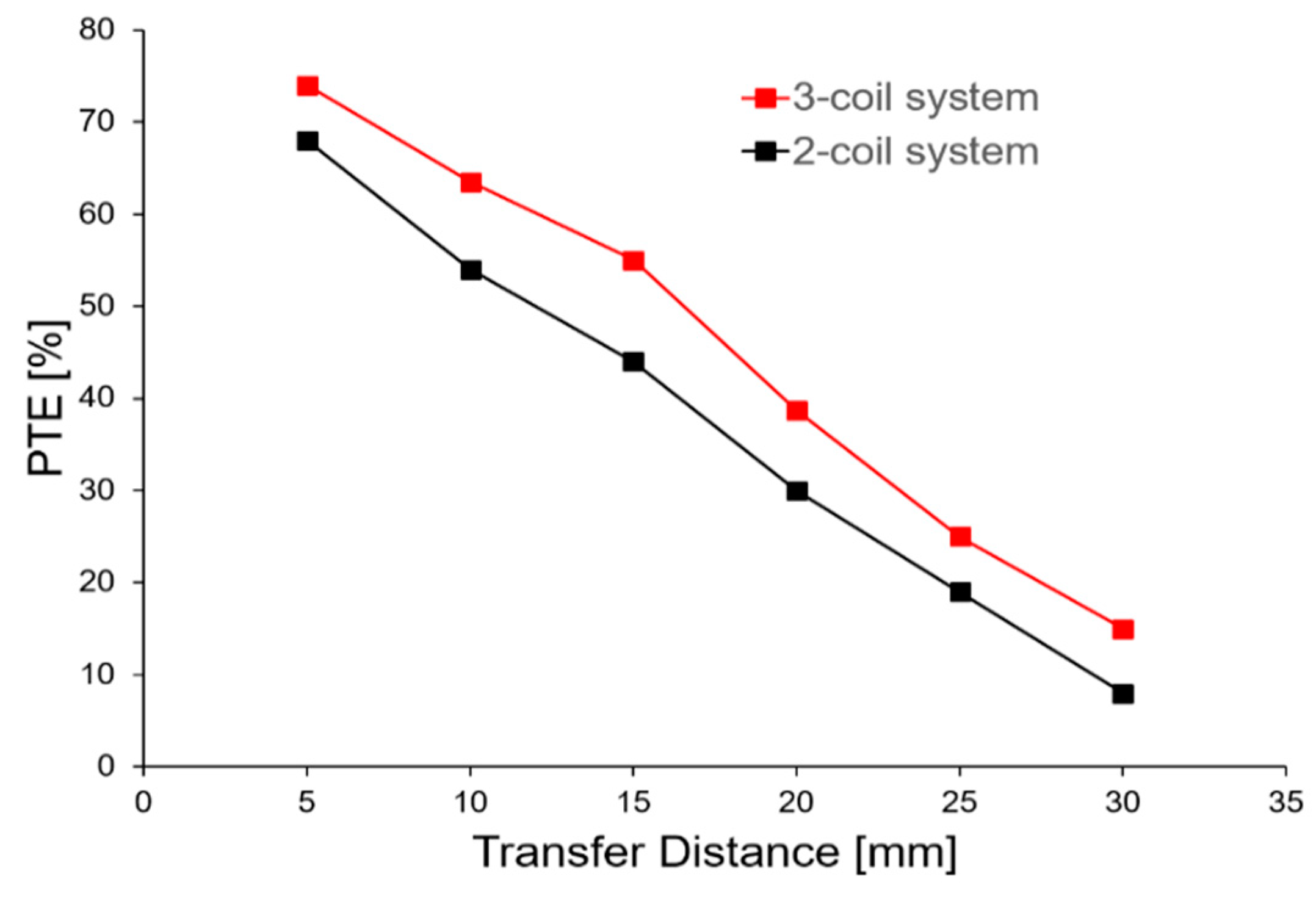
3.1. Power Transfer Efficiency

For the conventional WPT systems, the two-coil system using the primary (Qp) and the secondary coils (Qs) is commonly seen. The Q-factor of the coils and the coupling coefficient (k) determine the PTE, which is given by [12]:
η 2 - c o i l = k 2 Q p Q s 1 + k 2 Q p Q s
The coil lumped circuit is modeled as shown in Figure 5a, the total impedance around the resonant circuit is:
Z = R + j ω L + 1 / j ω C
where R, L, and C are the inductance, resistance, and capacitance of the circuit, and j is the imaginary constant. According to Kirchoff’s law, the induced current in the resonator is:
I = M d I e d t / Z
where Ie is the current applied in the driving coil, t is time. M is the mutual inductance between the driver and the load coils, which is expressed as:
M = k L d L l
Compared to the one driving coil systems, the direction of the AC passing through the two driving coils must be kept the same. Otherwise, the effective magnetic field may be mutually canceled and weakened. The schematic diagram of the 3-coil R-WPT system is shown in Figure 5b, where Vs is the power source applied to the primary coil and Rs is the source impedance. In this system, the induced current in the load coil L3 can be expressed as:
I 3 = ( M 13 · d I 1 d t + M 23 · d I 2 d t ) / | Z 3 |
From Equations (9) and (11), the induced current in the proposed two driving coil R-WPT system is much larger than that of the conventional WPT system given the same input power.

3.2. Simulation Results

Adopting the multi-turn multi-layer structure as shown in Figure 2, we wound 52 turns for both two driving coils and 55 turns for the receiver coil, respectively. Although increasing the number of the turns may increase the Q-factor of the coil, note that the AC resistance also gets increased accordingly, bringing negative influence on the Q-factor. In our design, a peak Q-factor was observed experimentally when the number of turns was around 54, while the Q-factor dropped when the number of turns was over 54. The detailed dimensions and geometric specifications of the three coils are given in Table 3. The driving and the load coils (functioned as the implantable coil) were concentric. The induced current was verified via COMSOL simulation using the coils’ physical parameters listed in Table 1 and Table 3. In this simulation, the distance between the driving and implant coils was 5 mm. The applied AC was 0.1 mA with a frequency of 2.2 MHz to each driving coils, Figure 6 depicts the cross section of the induced current density at the receiver side. This simulation result clarifies that power can be transferred wirelessly through the resonant system. Moreover, we can observe that the inner turns of the coil received more power than that of the outer of the coil, which is a reasonable outcome according to magnetic field theory. The ratio of the induced current to the applied current was about 12% with a transfer distance of 5 mm.
In the next simulation, the influence of distance and orientation to the PTE were investigated. In the simulation model, two co-axial driving coils and the load coil were positioned at a distance of 5 mm apart, the center axis of the driving coils were aligned with that of the load coil, we calculated the PTE, then the transfer distance was increased up to 25 mm, the correlated PTE versus distance were given in Figure 7a. A maximum PTE of 80% was achieved at a separation of 5 mm. As a comparison, same simulation conditions were applied to the 2T-1R model using only one driving coil. As expected, our design shows better PTE than its counterpart due to an increased mutual inductance between the driving and load coils. Locating the load coil 5 mm apart from the driving coils, we horizontally rotated the load coil with respect to the axis of driving coils, this may likely reflect the real scenario of wirelessly powering the implants. The PTE calculated versus the rotation angle were shown in Figure 7b. The shift and the rotation reduce the magnetic flux through the load coil, resulting in a decreasing coupling coefficient between the driving and the load coils. Consequently, the PTE drops with an increasing rotation angle.

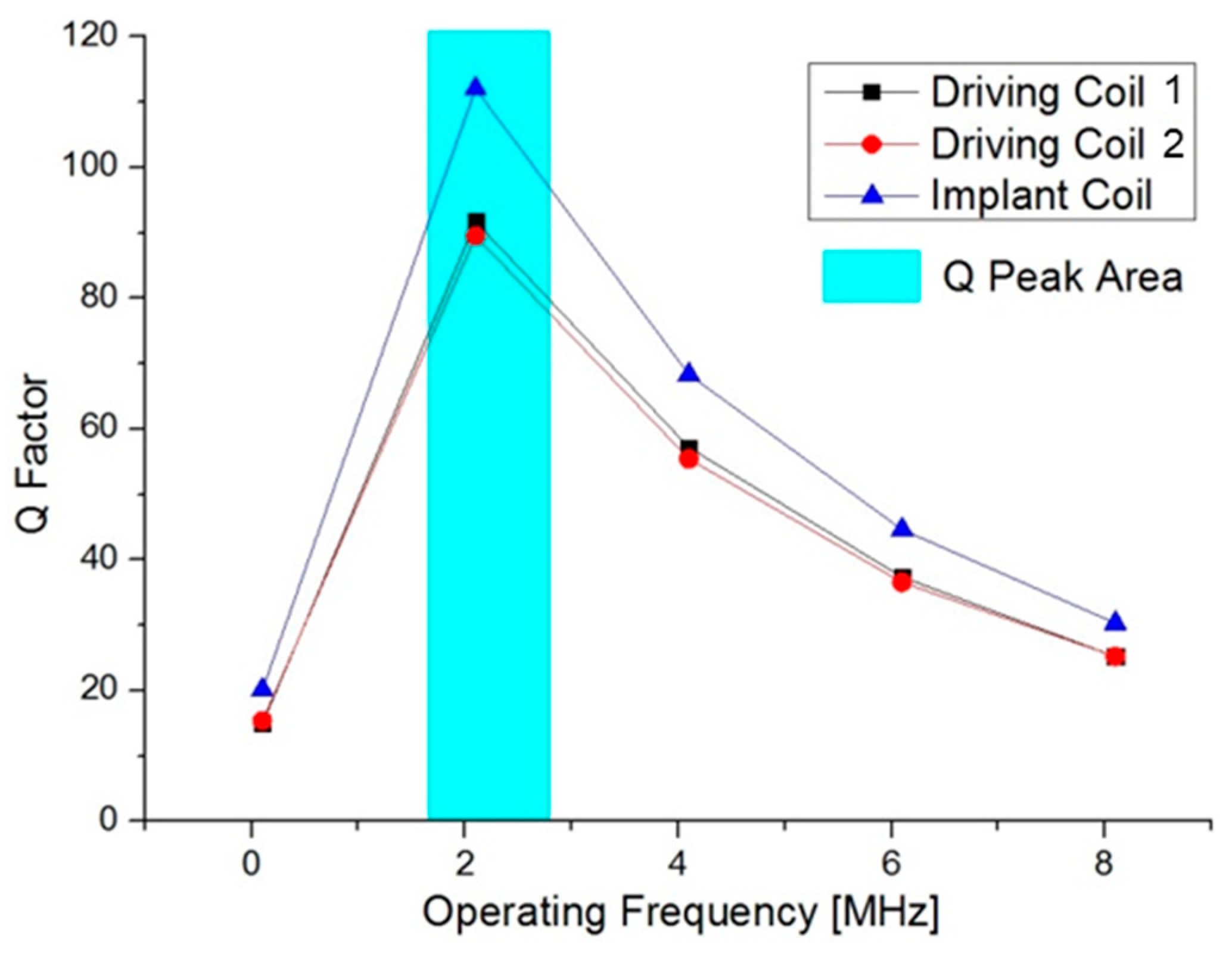
3.3. Experimental Measurements

To demonstrate the validity of the proposed two driving coil R-WPT technique, a measurement setup was implemented as shown in Figure 8 (left). An NI XI 5402 was used to apply 1 mW AC power to the driving coils, which were located on the opposite side of the load coil (the inset of Figure 8 (left)). With a transfer distance of d23 = 20 mm, the measured voltage waveforms of the driving and the implant coils were shown in Figure 8 (right). The received power was obtained by measuring the induced current and the voltage directly on the load coil. When the signal generator was tuned to f0 = 2.94 MHz, the induced voltage on the load coil exhibited a peak value (Vpp) of 5.52 V. In Figure 8 (right), the voltage of the driving coil was much lower than that of the load coil. The reason could mainly be that the number of turns of the load coil was larger than that of the driving coil [12]. Though, the induced current across the load coil was Ipp = 0.56 mA, much lower than the applied current on the driving coils in our measurements. The corresponding PTE was 38% (derived by the multiplication of the induced current Irms and voltage Vrms over the emitted power). Moreover, a phase difference between the input and output voltage waveforms was observed, this is because the coupling between the driving and the load coils may shift the original phase if the multiple transmitters are used [17]. As shown in Figure 9 (red dot), the PTE was measured at a different transfer distance d23 from 5 mm to 30 mm. The highest PTE is 74% at the distance of 5 mm (equal to near tissue thickness). Moreover, the PTE can keep a high value (38.7%) over a distance up to 20 mm (equal to deep tissue thickness). Table 4 summarizes the parameters of our proposed system, as well as the comparison with previously reported works in the literature.
As a comparison, a typical 2 coil system with an equivalent number of turns of the driving coils was also tested. Kept the same experimental setup, the AC power was applied to the driving coil (104 turns) and measured the PTE of the same load coil versus the distance, the results are represented by the black dot in Figure 9. As expected, we can clearly observe that our 3-coil system, with two driving coils and one load coil shows much better PTE than the 2-coil counterpart. This is because all the coils achieved their peak Q-factors in our design, while the Q-factor of the driving coil may deviate from its peak value in the 2-coil model, resulting in a lower PTE. Similar observations and results can be also found in [11], however, our work provided a simple load coil structure instead of designing two separate coils on the receiver side [11], which makes the implantable applications bulky and complicated.

4. Conclusions

This work presents a 3-coil R-WPT using a pair of driving coils which is intended to provide an improved PTE. The geometries of the coils are optimized through simulations, consequently, the coils achieve their peak Q-factors at the resonant frequency. Moreover, the influence of the transfer distance and orientation on the PTE is demonstrated. The results indicate that the proposed design provides a higher PTE than its 3-coil counterpart using only one driving coil in both cases. Finally, the performance of the proposed design is further validated via experiments, and the results show that the 3-coil system using two driving coils provides higher PTE compared to the 2-coil system with an equivalent geometry setting. Besides the PTE, the resonant frequency (or the operating frequency) is another critical factor for implantable applications. The selection of the frequency must be carefully considered in order to avoid safety concerns and electromagnetic wave interference. This will need in-depth and careful studies and further refinement efforts and will be part of our future work following the current feasibility study.

Author Contributions

Conceptualization, C.L. and Y.Y.; methodology, Y.Y.; validation, Y.Y. and R.H.; formal analysis, C.L. and B.W.; writing—original draft preparation, C.L.; writing—review and editing, C.L., B.W., R.H. and Y.Y.

Funding

This publication was made possible by NPRP grant NPRP11S-0104-180192 from the Qatar National Research Fund (a member of Qatar Foundation). The statements made herein are solely the responsibility of the authors.

Conflicts of Interest

The authors declare no conflicts of interest.

References

  1. Yi, Y.; Zaher, A.; Yassine, O.; Kosel, J.; Foulds, I. A remotely operated drug delivery system with an electrolytic pump and a thermo-responsive valve. Biomicrofluidics 2015, 9, 052608. [Google Scholar] [CrossRef] [PubMed] [Green Version]
  2. Yang, Z.; Liu, W.; Basham, E. Inductor modeling in wireless links for implantable electronics. IEEE Trans. Magn. 2007, 43, 3851–3860. [Google Scholar] [CrossRef]
  3. Yi, Y.; Buttner, U.; Foulds, I. A cyclically actuated electrolytic drug delivery device. Lab Chip 2015, 15, 3540–3548. [Google Scholar] [CrossRef] [PubMed]
  4. Xue, R.F.; Cheng, K.W.; Je, M. High-Efficiency Wireless Power Transfer for Biomedical Implants by Optimal Resonant Load Transformation. IEEE Trans. Circuits Syst. I Regul. Pap. 2013, 60, 867–874. [Google Scholar] [CrossRef]
  5. Yi, Y.; Chen, J.; Selvaraj, M.; Hsiang, Y.; Takahata, K. Wireless Hyperthermia Stent System for Restenosis Treatment and Testing with Swine Model. IEEE Trans. Biomed. Eng. 2019, (in press). [Google Scholar]
  6. Yi, Y.; Huang, R.; Li, C. Flexible substrate-based thermo-responsive valve applied in electromagnetically powered drug delivery system. J. Mater. Sci. 2019, 54, 3392–3402. [Google Scholar] [CrossRef]
  7. Baker, M.; Sarpeshkar, R. Feedback Analysis and Design of RF Power Links for Low-Power Bionic Systems. IEEE Trans. Biomed. Circuits Syst. 2007, 1, 28–38. [Google Scholar] [CrossRef] [PubMed]
  8. Han, L.; Li, L. Integrated wireless communications and wireless power transfer: An overview. Phys. Commun. 2017, 25, 555–563. [Google Scholar] [CrossRef]
  9. Catrysse, M.; Hermans, B.; Puers, R. An inductive power system with integrated bi-directional data-transmission. Sens. Actuators A Phys. 2004, 115, 221–229. [Google Scholar] [CrossRef]
  10. Yi, Y.; Buttner, U.; Fan, Y.; Foulds, I. Design and optimization of a 3-coil resonance-based wireless power transfer system for biomedical implants. Int. J. Circuit Theory Appl. 2014, 43, 1379–1390. [Google Scholar] [CrossRef]
  11. Kiani, M.; Jow, U.M.; Ghovanloo, M. Design and Optimization of a 3-Coil Inductive Link for Efficient Wireless Power Transmission. IEEE Trans. Biomed. Circuits Syst. 2011, 5, 579–591. [Google Scholar] [CrossRef] [PubMed] [Green Version]
  12. RamRakhyani, A.; Mirabbasi, S.; Chiao, M. Design and Optimization of Resonance-Based Efficient Wireless Power Delivery Systems for Biomedical Implants. IEEE Trans. Biomed. Circuits Syst. 2011, 5, 48–63. [Google Scholar] [CrossRef] [PubMed]
  13. Kurs, A.; Karalis, A.; Moffatt, R.; Joannopoulos, J.; Fisher, P.; Soljacic, M. Wireless Power Transfer via Strongly Coupled Magnetic Resonances. Science 2007, 317, 83–86. [Google Scholar] [CrossRef] [PubMed] [Green Version]
  14. Yi, Y.; Kosel, J. A remotely operated drug delivery system with dose control. Sens. Actuators A Phys. 2017, 261, 177–183. [Google Scholar] [CrossRef] [Green Version]
  15. Jow, U.; Ghovanloo, M. Design and Optimization of Printed Spiral Coils for Efficient Transcutaneous Inductive Power Transmission. IEEE Trans. Biomed. Circuits Syst. 2007, 1, 193–202. [Google Scholar] [CrossRef] [PubMed]
  16. Kim, J.W.; Son, H.C.; Kim, K.H.; Park, Y.J. Efficiency Analysis of Magnetic Resonance Wireless Power Transfer With Intermediate Resonant Coil. IEEE Antennas Wirel. Propag. Lett. 2011, 10, 389–392. [Google Scholar] [CrossRef]
  17. Ahn, D.; Hong, S. Effect of Coupling Between Multiple Transmitters or Multiple Receivers on Wireless Power Transfer. IEEE Trans. Ind. Electron. 2013, 60, 2602–2613. [Google Scholar] [CrossRef]
  18. Arakawa, T.; Coguri, S.; Krogmeier, J.V.; Kruger, A.; Love, D.J.; Mudumbai, R.; Swabey, M.A. Optimizing Wireless Power Transfer from Multiple Transmit Coils. IEEE Access 2018, 6, 23828–23838. [Google Scholar] [CrossRef]
  19. Park, S.; Kim, M. Numerical Exposure Assessment Method for Low Frequency Range and Application to Wireless Power Transfer. PLoS ONE 2016, 11, e0166720. [Google Scholar] [CrossRef] [PubMed]
  20. Christ, A.; Douglas, M.; Nadakuduti, J.; Kuster, N. Assessing Human Exposure to Electromagnetic Fields from Wireless Power Transmission Systems. Proc. IEEE 2013, 101, 1482–1493. [Google Scholar] [CrossRef]
Figure 1. Illustration of an electric field induced by a varying magnetic field.
Energies 12 02914 g001
Figure 2. The driving coils’ cross section (Din: Inner conductor loop, Dout: Outer conductor loop, OD: Outer diameter) with multi-layer and multi-turn structure (left); cross sections of single turn with multi-strand wires (right).
Energies 12 02914 g002
Figure 3. Inductance simulation of driving coils and implant coil with multi-layer and multi-turn versus different frequency.
Energies 12 02914 g003
Figure 4. Q-factors’ curves versus operating frequency.
Energies 12 02914 g004
Figure 5. (a) Basic coil lumped circuit; (b) circuit model of the 3-coil R-WPT system.
Energies 12 02914 g005
Figure 6. Cross section of surface current density of implant coil in COMSOL simulation when the transfer distance is 5 mm.
Energies 12 02914 g006
Figure 7. PTE calculated versus (a) transfer distance and (b) rotation angle in the simulation.
Energies 12 02914 g007
Figure 8. The experimental setup for the three-coil WPT system (left); The measurement results of the input voltage (on driving coil) and output voltage (on load coil), d23 = 20 mm (right).
Energies 12 02914 g008
Figure 9. PTE measurements for the proposed 3-coil system and typical 2-coil system.
Energies 12 02914 g009
Table 1. Litz wire property.
Radius of wire per strand, rs19.9 [µm]
Number of strands, Ns20
Area efficiency, β55%
Conductivity, σ58 [S/mm2]
Isolation Thickness, ζ3 [µm]
Inner radius, r0110 [µm]
Relative permittivity, εr3
Table 2. Experimental verification of coils’ Q factor and inductance: (M) denotes measurement; and (S) denotes simulation result.
Coil Num.Inductance M
(2.5 MHz)
Inductance S
(2.5 MHz)
Resistance M
(2.5 MHz)
Q-factor M
(2.5 MHz)
Q-factor S
(2.5MHz)
155 uH49 uH11 Ω8290
253 uH46 uH11 Ω7887
334 uH27 uH5 Ω95112
Table 3. Coils’ physical specification by measurements.
TypeCoil Num.Outer Dia.
(mm)
Inner Dia.
(mm)
Turn/Layers
Nt
Layers
Na
DC Resistance
(Ω)
Capacitance
(pF)
Driving Coil121121342.2110
Driving Coil221121342.5110
Load Coil31261151.8200
Table 4. Comparison with previous works.
Ref.DesignSize (cm)Frequency (MHz)Distance (λ·10−3)PTE
[10]2T-1RTx: π × 1.52
Rx: π × 1.752
6.760.3417%
[11]1T-2RTx: π × 2.152
Rx: π × 0.52
13.560.4578.6%
[17]1T-2RTx: 35 × 30
Rx: 31.5 × 22.5
0.660.3559.7%
This work2T-1RTx: π × 0.62
Rx: π × 0.32
2.90.0574%
This work2T-1RTx: π × 0.62
Rx: π × 0.32
2.90.238%

